Best Of
Re: American Standard Aqua Seal Faucet
Where is it leaking? Is it dripping from the spout or is the packing/o-ring around the steam leaking? Anyone with a little experience should know where to get parts for it. Once the parts are replaced properly it should be good for another 5 years to couple decades depending on your water and usage.
 mattmia2
Re: Trying to understand wiring for heating system
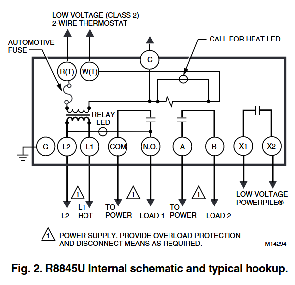
X1,X2 should make and break the millivolt circuit to the gas valve.
 HVACNUT
Re: Trying to understand wiring for heating system
You need to list the components you have
Model of zone valve(s) and quantity
How many thermostats
Do you have an indirect water heater or tankless water heater (probably not the later) ?
quantity of circulators
24 volt gas valve or milivolt gas valve
number of transformers
and more pictures

Re: Trying to understand wiring for heating system
I would think the electrical control part of your system could be made to be more reliable than it is. IMO it should not be failing every few years.
From your pictures it does look like a milivolt system as far as the electrical control at the gas valve. The rest, thermostats and relay units are probably 24 VAC which is powered by the 120 VAC building power.
Millivolt systems are very sensitive to poor connections that create excessive voltage drop. So the wiring of the millivolt part should be set up to minimize unneeded connections.
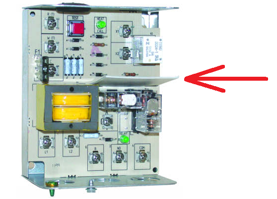
I think it should work when connected correctly with minimal connections. I would think either the A-B contacts or the X1-X2 contacts would work, however the X1-X2 contacts are specified for low voltage and Powerpile (millivolt) service due to the isolation barrier (Red arrow) between high and low voltage part of the system. And also the contacts of that relay may be more suitable for Powerpile (millivolt) service. IMO the R8845U(s) should be as close to the gas valve as possible to minimize wiring losses.
More pictures of the rest of the electrical equipment would help, thermostats, relays, zone valves, wiring.
The Red Test button inside the R8845U may be helpful for isolating the defective part of the control system.
 109A_5
Re: Trying to understand wiring for heating system
the output of the thermopile falls over the years too, it needs replacement every few decades. it is possible that the zone that works has shorter or heavier gauge wiring than the zone that doesn't
mattmia2
Re: Trying to understand wiring for heating system
The yellow wires on the zone valve are the motor, they open the valve when they get 24vac.
The red wires are the end switch on the zone valve. They are likely in parallel on the thermostat input of the circulator relay. The end switch closes the relay and the relay turns on the circulator and fires the boiler.
mattmia2
Re: Trying to understand wiring for heating system
Looks like you have a multimeter, good. It looks like there is 4 voltages in use with your system.
3 VDC the thermostat batteries.
The pilot generated millivolt system nominally about 0.750 Volts DC no load. Will be less under load of the gas valve.
120 VAC, for the Circulator Pump and the primary side of the transformers used to produce the 24 VAC.
24 VAC, thermostat control wiring and Zone Valves and parts of the R8845U relay.
Basically when the thermostat(s) call for heat (contacts close) it should provide power to the Zone Valve motor. (the 24 VAC is provided by the transformer near the Red cover plate safety switch).
When the zone valve motor fully opens the zone valve the zone valve's End Switch closes.
The closed End Switch then activated the respective R8845U relay.
The R8845U relays do two things, switches the circulator pump on and switches on the Gas Valve powered by the millivolt Powepile. They should be wired so either thermostat call for heat energizes the circulator and the boiler's burner (the Gas Valve).
When the thermostat is satisfied and opens its switch everything releases.
BTW you really only needed one R8845U relay. Since the Zone Valve End Switches could be paralleled to control one R8845U relay. Either way will work. The logical 'OR' that is needed (two zones and one boiler & circulator) can happen at either of two places on the input to one R8845U relay or the output of two R845U relays.
109A_5
Re: Trying to understand wiring for heating system
The powerpile/milivolt gas valve system is its own power source — the power pile itself (sort of a takeoff on a thermocouple) generates a very small voltage proportional to its temperature — which is sufficient,, if it's warm enough — to open the gas valve. So… the powerpile is heated by the pilot flame, and when the circuit through the gas valve is closed the gas valve opens and the burner operates.
No outside transformer needed!
However. It's pretty weak. So any problems in the wiring — or the switch calling for heat — can defeat it.
Therefore… use the X1 and X2 contacts, which are intended for very low voltage and very low current (there is a reason that Taco notes they are for powerpile/millivolt use!) rahter than A and B terminals which are intended for switching literally hundreds of times the voltage and current (120 volts at several amperes) of the X1 and X2. but which may have much too much resistance to switch the millivolt power.

Re: pls help me id "epoxy" substance
Hi, Can I hazard a guess that this is a drain line? If so, A good fix would be to cut out the cracked part and use no-hubs to replace the pipe. Some Band-aids like stretchy silicon rubber tape can last a very long time, but are still considered a patch. As the cast iron loses integrity, other problems like sagging can crop up, which is a reason to go with the most durable fix. In the long run, this will save you time.
Yours, Larry

Re: Cleaning HVAC Ductwork?
Unless they run a camera thru the entire ductwork, live, to prove to you that it's actually ALL clean and sanitized. Which they won't, because it won't be.
