Best Of
Re: Steam From Scratch
I’ve always liked the photo of the journeyman in the jacket, tie and fedora helping to carry a radiant assembly. Imagine.

Re: Melted Coil drain pan
Restricted air flow (plugged filter or evaporator or other air flow restriction) and an inoperative high limit switch.
 109A_5
Re: How can I use 90 F degree water to heat my new house?
I visited the Peppermill in Reno a few years back and got a tour of their geothermal system which heats and provides DHW for the entire resort, 2.1 million feet of space. They pump and dump.
One pump pulling 176° F from the well, another discharge to help pump back down a well across the property.
 hot_rod
Re: Cast iron radiator shipping
I went back to my radiator supplier in Chicago, Consumer’s Supply. I got two pressure tested cast iron radiators; one tube, one column, both primed and shipped to Vegas for $1327.00. These guys, the Brenner Family and Luis, the warehouse manager, are the best.

Re: Why Carbon Monoxide Is So Dangerous
@Steamhead yes sir scary I brought my co detector on vacation to check the hotel rooms lol
@Mad Dog_2 thank you

Re: Options for more attractive insulation for the steam main running through this basement unit?
They must have had religious services in the basement. It would be the farthest from heaven for that type of religious service. 😈 😈 😈
As far as proper, good-looking insulation, you could cover what you have with vinyl. Then get fitting insulation with a vinyl cover to make everything white.
The antler needs to be pitched so that condensation does not get trapped in the horizontal sections. How long they are probably does not matter. . The same company has elbow and tee insulation fittings that use the same vinyl to cover the fitting insulation.
OR… you can try to miter the elbows with two 22.5° angle curs and vinyl tape for the 90° elbow joints.

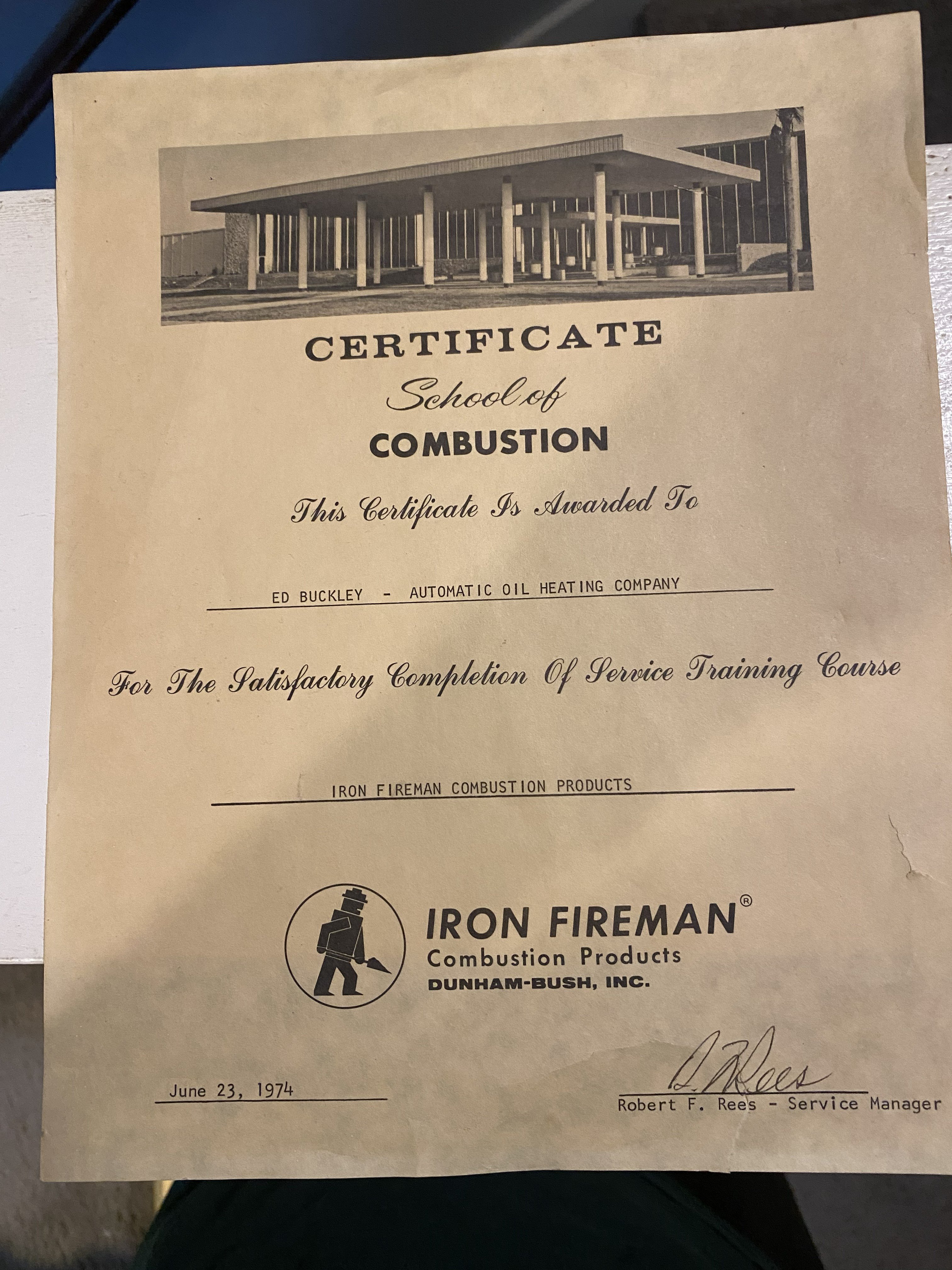
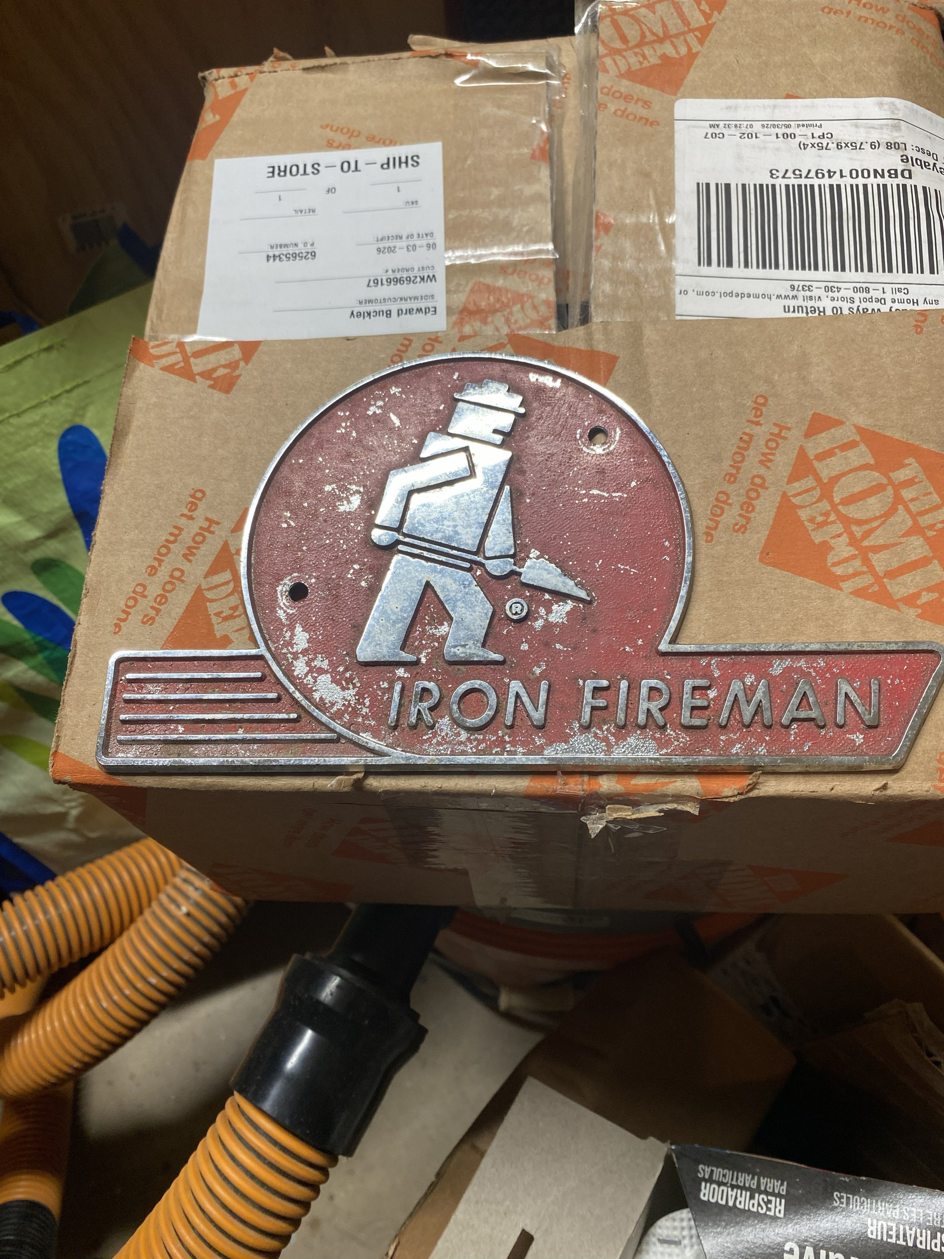
Re: Iron Fireman
I have had this since my Iron Fireman burner days. Stripped it off a burner that was going to the scrap. Now it is screwed to some shelves in my truck.
First factory burner school I went to (and I think my first ever airplane ride !!!!) Allegheny Airlines from Hartford to Staunton, VA then a puddle jumper from Staunton to Harrisonburg.
Those were the days!!
Can't believe it's been 52 years


Re: Richardson
You'll want to choose the trap carefully, since the vent holes in Richardson return elbows are rather small. I'd use a Hoffman 17C with a Dura-Stat inside (which current models have) since the air throughput of the DuraStat is lower than usual.

Re: Cast iron radiator shipping
Hi, Any chance of a ReStore… Habitat For Humanity being closer by and having radiators? I seem to remember Urban Ore in Berkeley as a source too.
Yours, Larry

Re: Cast iron radiator shipping
@Steve Minnich, here's a list we've been compiling of places that sell used radiators:
