Trying to understand wiring for heating system

I’ve been maintaining my ancient Hydrotherm furnace ever since I bought my house. Every few years I research and get it working but it eventually fails. Last attempt I installed an R8845U to control the two Honeywell zone valves, the baseboard water pump, and the furnace (gas valve and furnace switch). This worked fine until only one of the thermostats would turn the system on.
I did a query on grok AI assistant) which insisted I need an R8845U for each of the two zones. I installed a second and wired up the 120V no problem. Each thermostat can control the baseboard pump correctly.
The 24V circuit is more confusing to me. Grok insists I use the A B terminals / relay in the R8845U (I had previously used the X1 X2 terminals / relay).
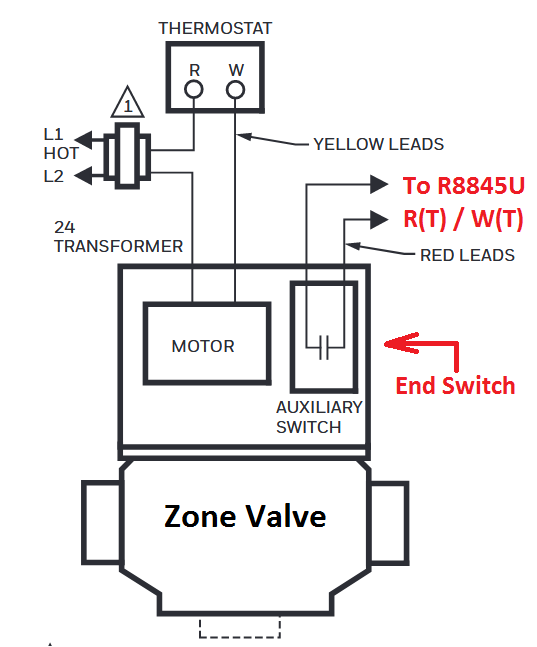
The zone valve 4 wires seem to control the motor and end switch separately.
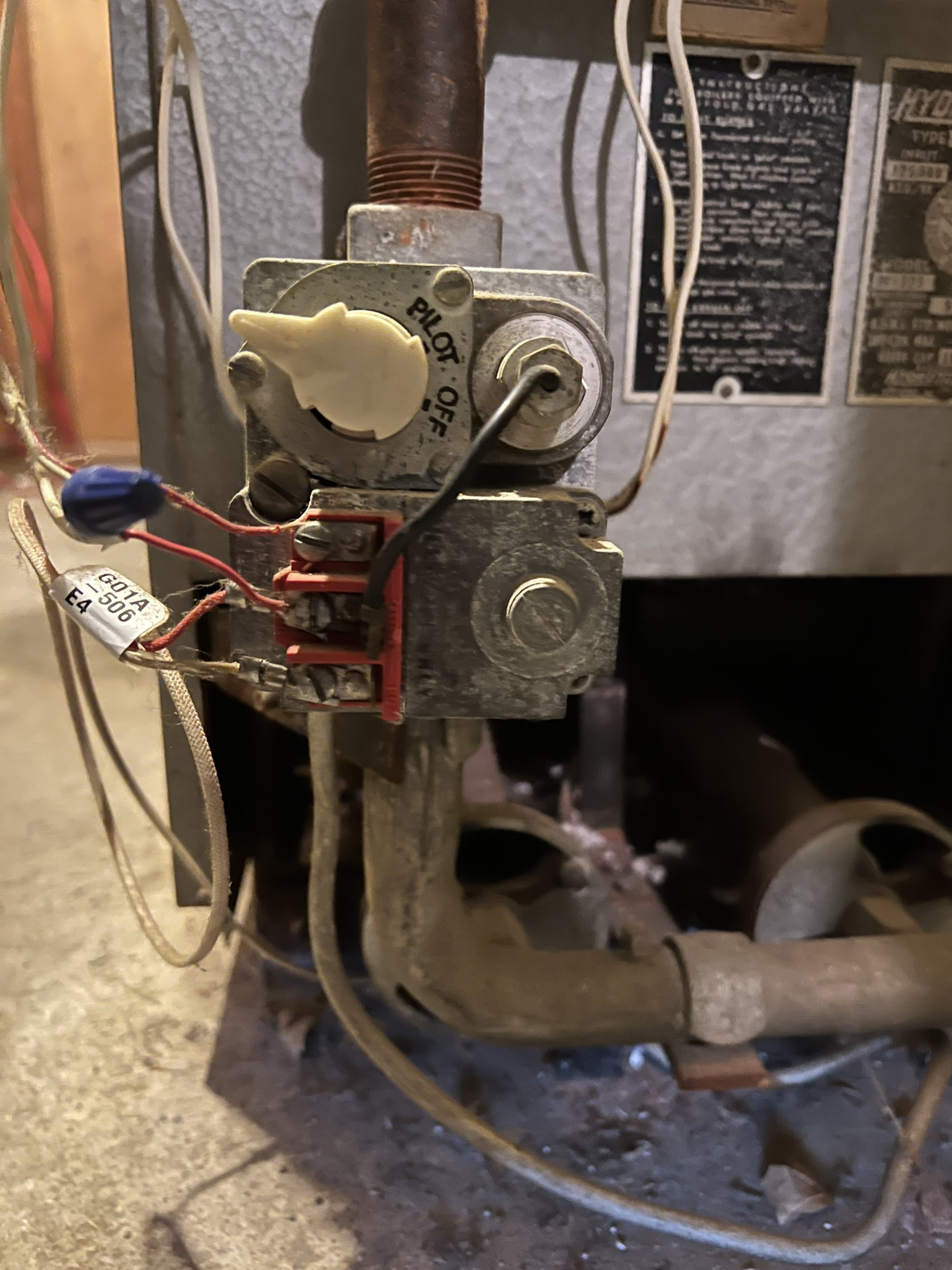
I seem to recall the gas valve (attached photo) may be a milli-volt control but I am not certain.
Any help is greatly appreciated!

Comments
-
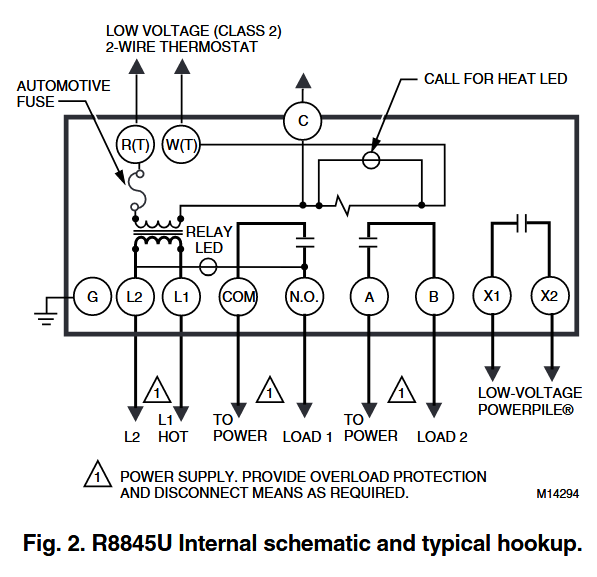
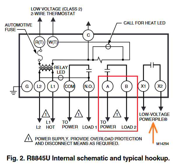
X1,X2 should make and break the millivolt circuit to the gas valve.
1 -
You need to list the components you have
Model of zone valve(s) and quantity
How many thermostats
Do you have an indirect water heater or tankless water heater (probably not the later) ?
quantity of circulators
24 volt gas valve or milivolt gas valve
number of transformers
and more pictures
2 -
I would think the electrical control part of your system could be made to be more reliable than it is. IMO it should not be failing every few years.
From your pictures it does look like a milivolt system as far as the electrical control at the gas valve. The rest, thermostats and relay units are probably 24 VAC which is powered by the 120 VAC building power.
Millivolt systems are very sensitive to poor connections that create excessive voltage drop. So the wiring of the millivolt part should be set up to minimize unneeded connections.
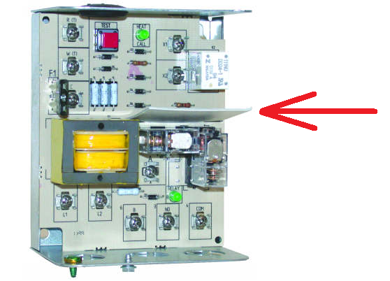
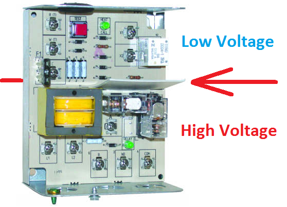
I think it should work when connected correctly with minimal connections. I would think either the A-B contacts or the X1-X2 contacts would work, however the X1-X2 contacts are specified for low voltage and Powerpile (millivolt) service due to the isolation barrier (Red arrow) between high and low voltage part of the system. And also the contacts of that relay may be more suitable for Powerpile (millivolt) service. IMO the R8845U(s) should be as close to the gas valve as possible to minimize wiring losses.
More pictures of the rest of the electrical equipment would help, thermostats, relays, zone valves, wiring.
The Red Test button inside the R8845U may be helpful for isolating the defective part of the control system.
 National - U.S. Gas Boiler 45+ Years Old
Steam 300 SQ. FT. - EDR 347
One Pipe System1 -
the output of the thermopile falls over the years too, it needs replacement every few decades. it is possible that the zone that works has shorter or heavier gauge wiring than the zone that doesn't
1 -
Thanks for the feedback! Additional photos of remaining elements of the heating system below.
It seems to me the A/B and X1/X2 terminals are simply a relay connecting a circuit to a relay controlled by the R8845U via. thermostat.
For the zone valve motor I would think I connect transformer hot (red) to A, zone valve yellow (motor wire hot) to B, zone valve yellow wire (motor wire common) to transformer common (white)?
If the gas valve is millivolt, what is the power source? Is there another transformer internal to the R8845U?
The Honeywell thermostats (one for upstairs, one for downstairs).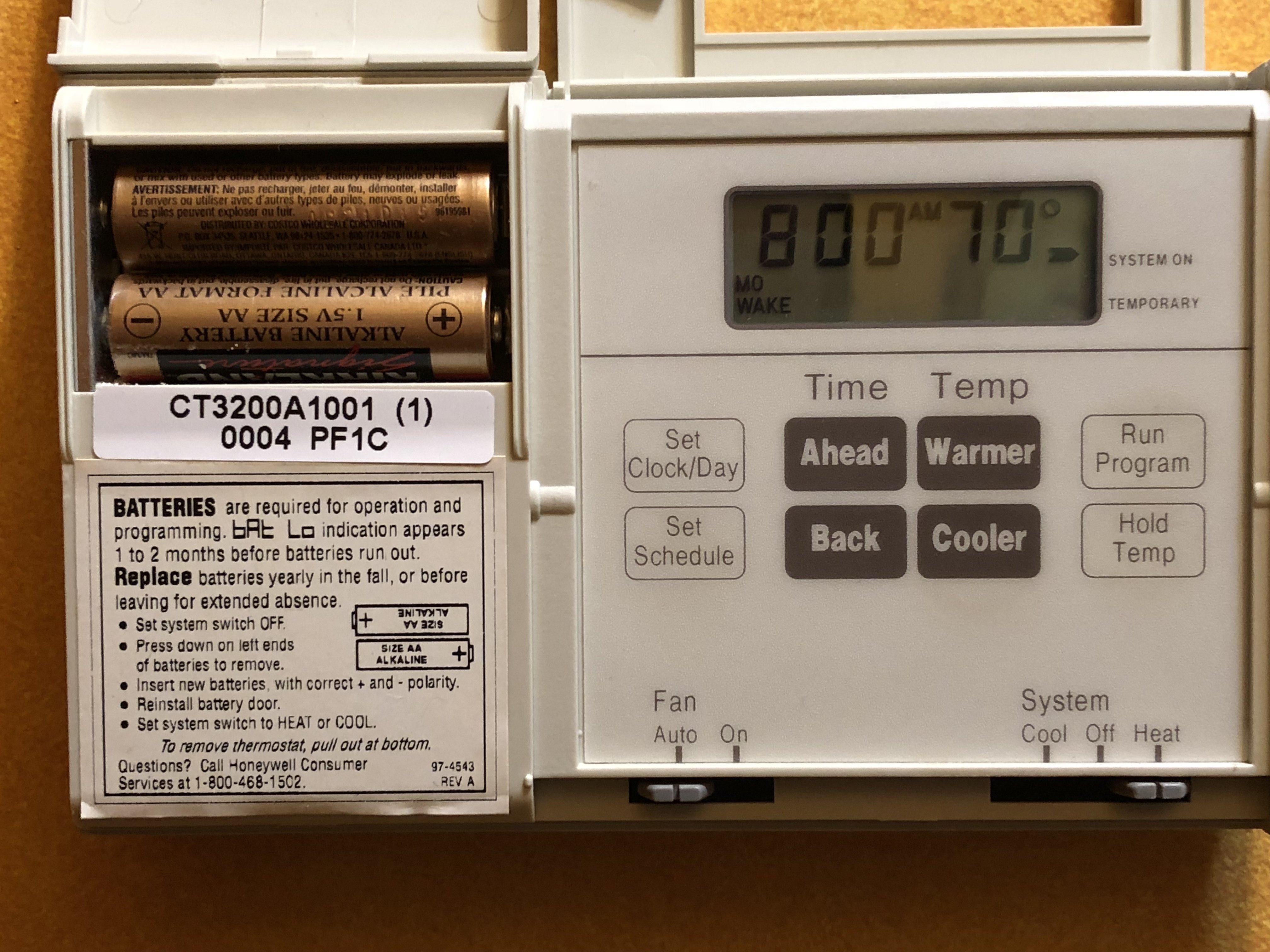
The main switch, 24V transformer, two R8845U units.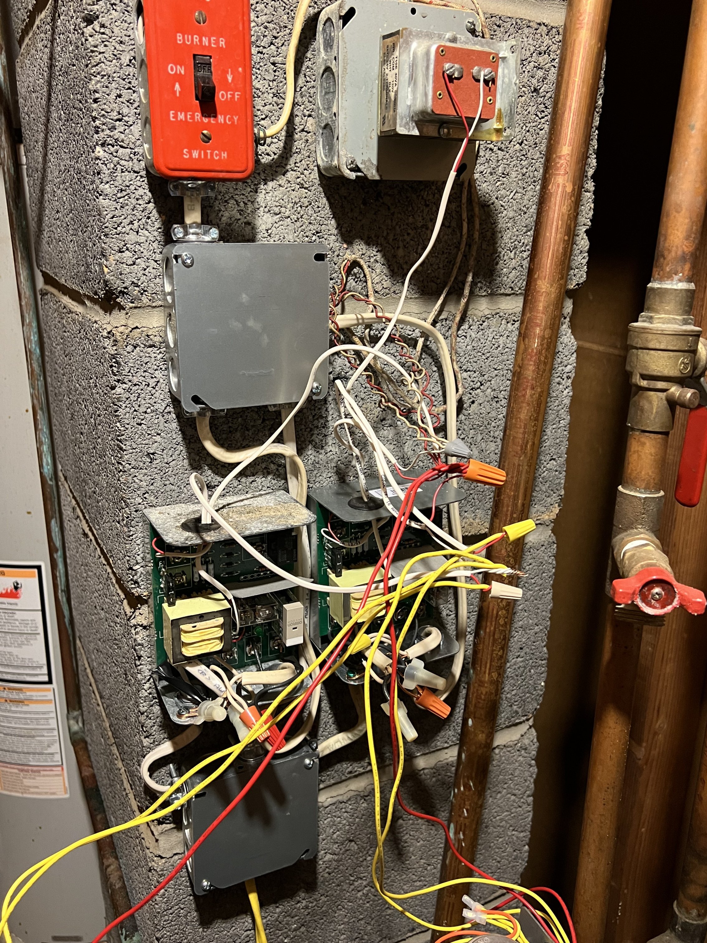
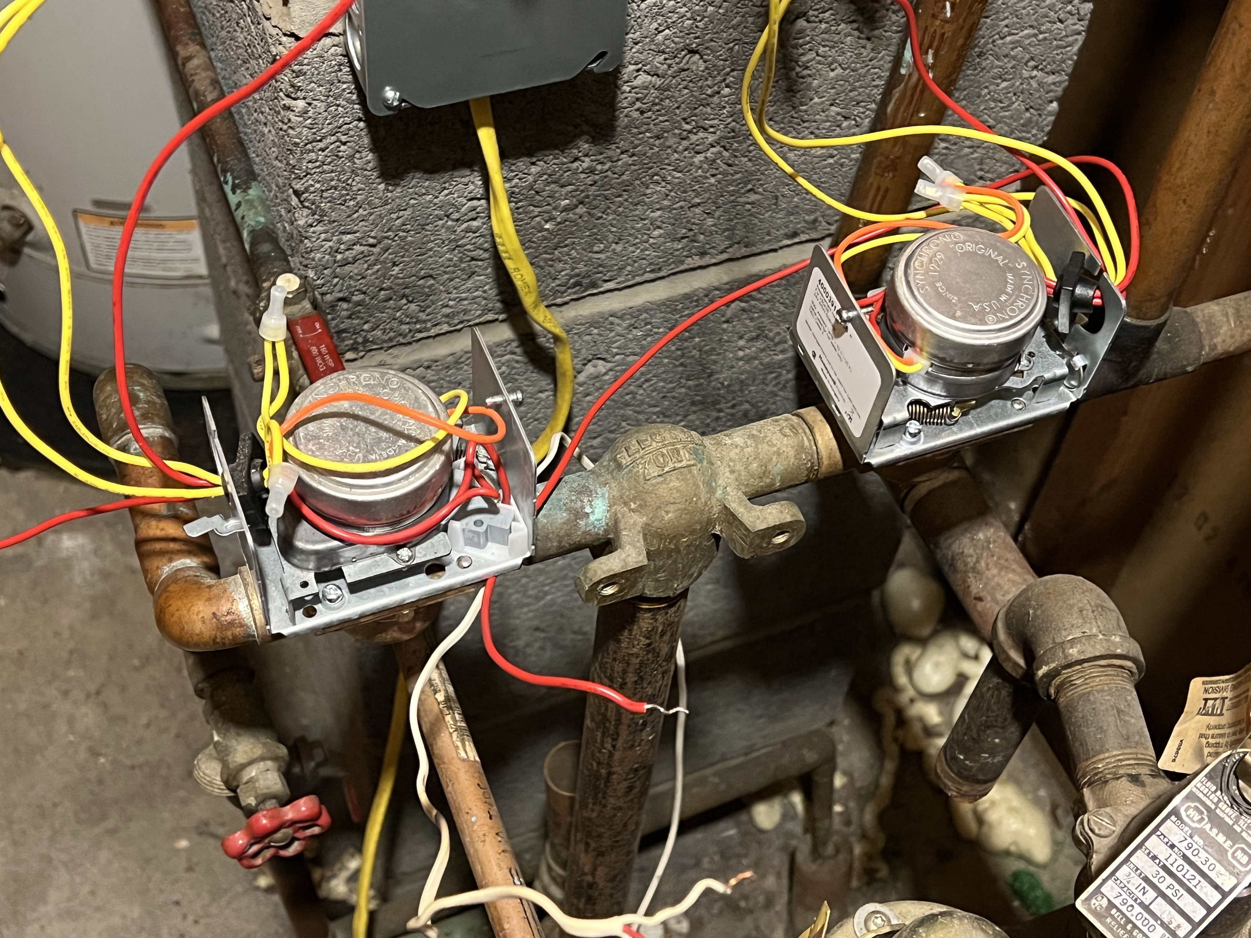
The two Honeywell 40003916 zone valves.
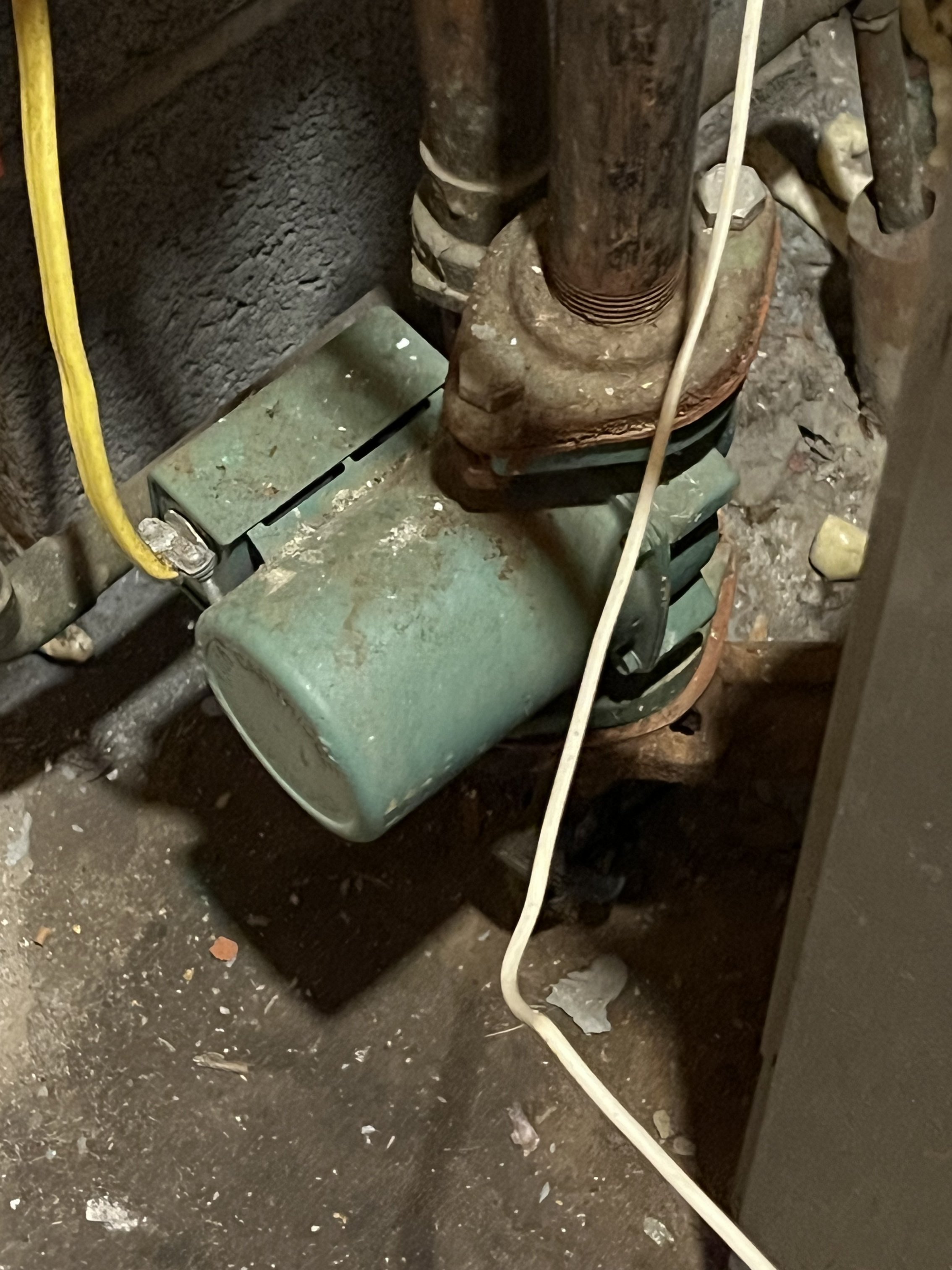
The water pump.
The furnace.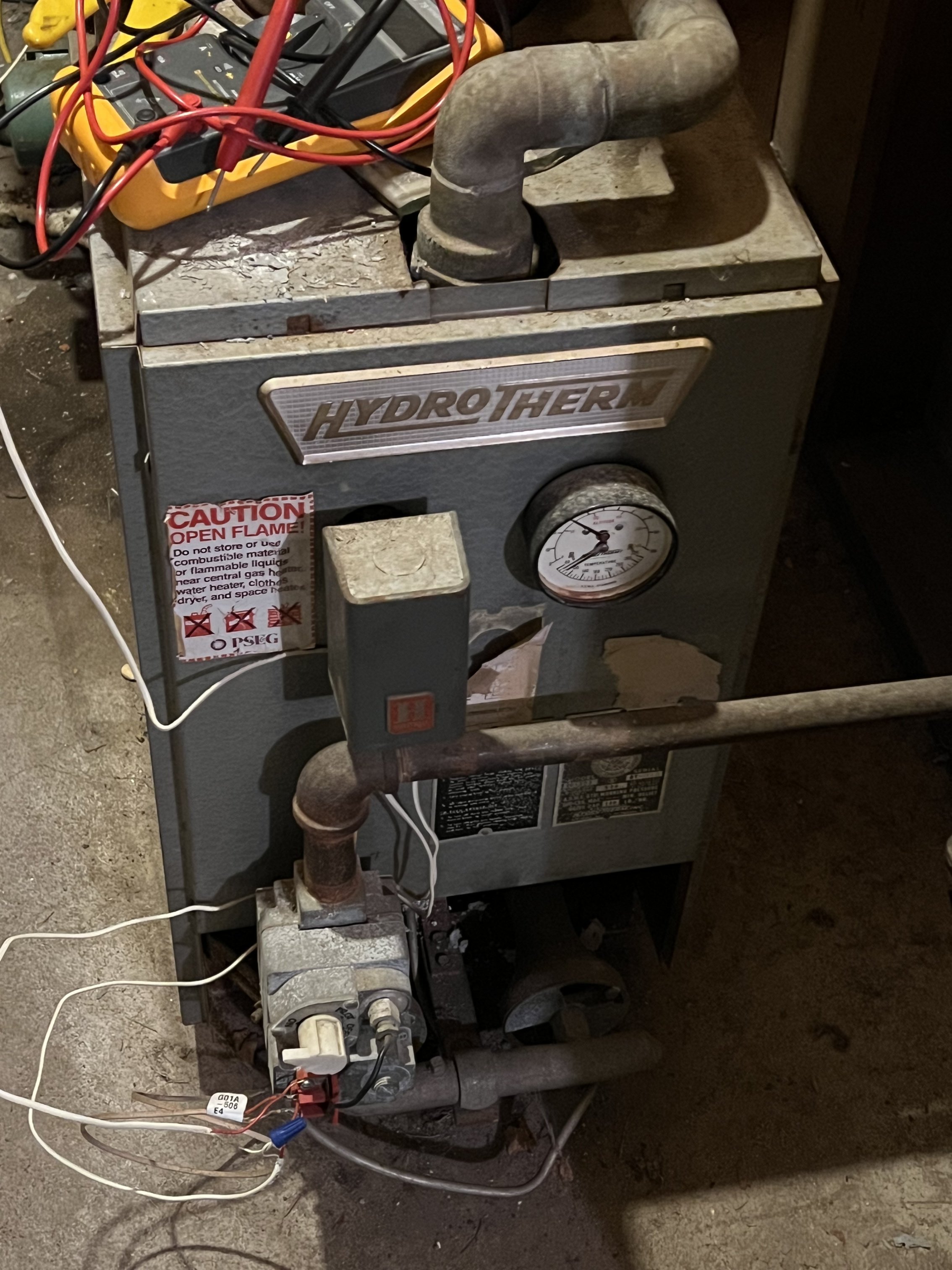 0
0 -
The powerpile/milivolt gas valve system is its own power source — the power pile itself (sort of a takeoff on a thermocouple) generates a very small voltage proportional to its temperature — which is sufficient,, if it's warm enough — to open the gas valve. So… the powerpile is heated by the pilot flame, and when the circuit through the gas valve is closed the gas valve opens and the burner operates.
No outside transformer needed!
However. It's pretty weak. So any problems in the wiring — or the switch calling for heat — can defeat it.
Therefore… use the X1 and X2 contacts, which are intended for very low voltage and very low current (there is a reason that Taco notes they are for powerpile/millivolt use!) rahter than A and B terminals which are intended for switching literally hundreds of times the voltage and current (120 volts at several amperes) of the X1 and X2. but which may have much too much resistance to switch the millivolt power.
Br. Jamie, osb
Building superintendent/caretaker, 7200 sq. ft. historic house museum with dependencies in New England1 -
The yellow wires on the zone valve are the motor, they open the valve when they get 24vac.
The red wires are the end switch on the zone valve. They are likely in parallel on the thermostat input of the circulator relay. The end switch closes the relay and the relay turns on the circulator and fires the boiler.
1 -
Looks like you have a multimeter, good. It looks like there is 4 voltages in use with your system.
3 VDC the thermostat batteries.
The pilot generated millivolt system nominally about 0.750 Volts DC no load. Will be less under load of the gas valve.
120 VAC, for the Circulator Pump and the primary side of the transformers used to produce the 24 VAC.
24 VAC, thermostat control wiring and Zone Valves and parts of the R8845U relay.
Basically when the thermostat(s) call for heat (contacts close) it should provide power to the Zone Valve motor. (the 24 VAC is provided by the transformer near the Red cover plate safety switch).
When the zone valve motor fully opens the zone valve the zone valve's End Switch closes.
The closed End Switch then activated the respective R8845U relay.
The R8845U relays do two things, switches the circulator pump on and switches on the Gas Valve powered by the millivolt Powepile. They should be wired so either thermostat call for heat energizes the circulator and the boiler's burner (the Gas Valve).
When the thermostat is satisfied and opens its switch everything releases.
BTW you really only needed one R8845U relay. Since the Zone Valve End Switches could be paralleled to control one R8845U relay. Either way will work. The logical 'OR' that is needed (two zones and one boiler & circulator) can happen at either of two places on the input to one R8845U relay or the output of two R845U relays.
National - U.S. Gas Boiler 45+ Years Old
Steam 300 SQ. FT. - EDR 347
One Pipe System1 -
The thermostats control the R8845U relays using the R(T) / W(T) terminals through the transformer to provide 24V when respective thermostat calls for heat. This certainly controls the 120V circulator pump circuit which is currently working properly.
Still not sure about the zone valves. Should I connect the yellow (motor) wires to the R8845U A/B terminals (through the transformer) for 24V switching? Or should these be connected right to the thermostats (through the transformer) for 24V switching?
It sounds like I could use the X1/X2 terminals for both R8845U to control the furnace / gas valve. This would require splicing to the connections for the furnace to control the gas valve and furnace switch. If so, then it seems there's no need to connect the zone valve red wires (end switch) as they would not be needed for the furnace? Or, if the zone valves red wires (end switch) connect to the furnace then I would not need to hook up the X1/X2 terminals?
I had a backup R8845U in case the primary failed so wiring up the second didn't seem too unreasonable at the time.0 -
Let's try again. You MUST use the X1/X2 terminals to control the gas valve on the boiler. That's a millivolt system, and must not be connected to anything else.
Br. Jamie, osb
Building superintendent/caretaker, 7200 sq. ft. historic house museum with dependencies in New England1 -
There is something wrong with this statement.
" The thermostats control the R8845U relays using the R(T) / W(T) terminals through the transformer to provide 24V when respective thermostat calls for heat. This certainly controls the 120V circulator pump circuit which is currently working properly. "
R8845U relay supplies it own 24 VAC power (internal transformer) for the R(T) / W(T) terminals. The R(T) / W(T) terminals only require a contact closure for proper operation.
" Should I connect the yellow (motor) wires to the R8845U A/B terminals (through the transformer) for 24V switching? "
No !!!
" Or should these be connected right to the thermostats (through the transformer) for 24V switching? "
Basically Yes.
The way it should work (with more detail and only one R8845U relay used). It is a series sequence of events, and it has a proper order with electrically isolated parts. For safety, functionality and proper logistics.
When the thermostat(s) call for heat (contacts close R/W) it should provide power to the Zone Valve motor (Yellow wires). (the 24 VAC is provided by the transformer near the Red cover plate safety switch).
When the Zone Valve motor fully opens the Zone Valve the Zone Valve's End Switch closes. This provides proof that the Zone Valve is open and water can flow. You don't want the boiler firing and the circulator running into closed Zone Valves.
This proof of an open Zone Valve (one or more) by their End Switch closing (Red wires) is connected to the R8845U relay's R(T) / W(T) terminals. Since you have two thermostats and two Zone Valves typically the Red Zone Valve wires are connected in parallel to provide two paralleled switches connected to the R(T) / W(T) terminals of the R8845U relay. This allows either thermostat via the Zone Valve to trigger the R8845U relay.
The R8845U relay contacts only turns on the Circulator pump (Load 1) and the burner X1 / X2.
In your case there is no second load (Load 2), so the A / B terminals of the R8845U relay would not be used and should not be used. Load 1 is the circulator pump. X1 / X2 provides isolated control for the millivolt part of the system. Relay contacts depending on the application are made of different materials and alloys. I suspect (without looking at the data sheet) that the relay X1 / X2 is better suited for the low voltage (millivolt) applications. Plus it is physically isolated away from the high voltage part of the R8845U relay.
 National - U.S. Gas Boiler 45+ Years Old
Steam 300 SQ. FT. - EDR 347
One Pipe System0 -
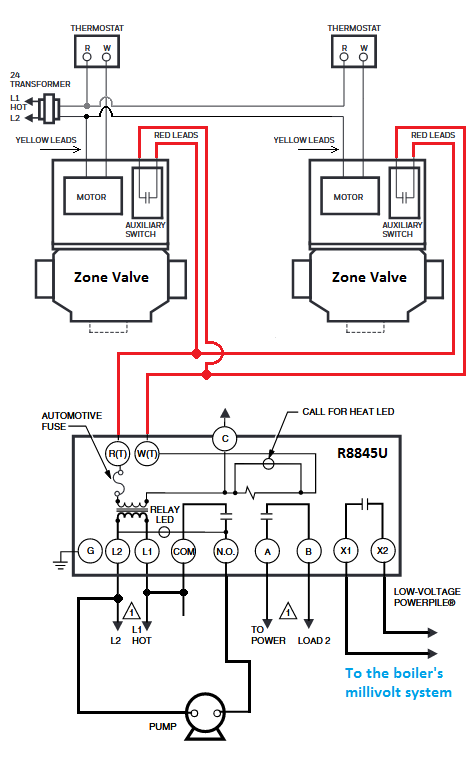
More of an overall wiring diagram using one R8845U relay.
Think of this control order;
Thermostat
Zone Valve
R8845U relay
Gas Valve & Circulator
 National - U.S. Gas Boiler 45+ Years Old
Steam 300 SQ. FT. - EDR 347
One Pipe System0 -
Regarding:
" It sounds like I could use the X1/X2 terminals for both R8845U to control the furnace / gas valve. This would require splicing to the connections for the furnace to control the gas valve and furnace switch. If so, then it seems there's no need to connect the zone valve red wires (end switch) as they would not be needed for the furnace? Or, if the zone valves red wires (end switch) connect to the furnace then I would not need to hook up the X1/X2 terminals?
I had a backup R8845U in case the primary failed so wiring up the second didn't seem too unreasonable at the time. "
As explained above the X1 / X2 terminals should be used to control the boiler's gas valve.
One problem is splicing, that adds resistance to a millivolt system that is not very tolerant of excessive resistance. Splices should be avoided. With only one R8845U relay there is less wire and less connections needed to make the millivolt part of the system work.
As explained above the Red wires (End Switch) is a desired and expected functional part of the system.
Using two R8845U is probably not unreasonable, just unnecessary, and complicates the wiring and may add unnecessary resistance to the millivolt part of the wiring if not done carefully with minimizing parasitic resistance in mind.
Usually the simpler the control system the easier it is to troubleshoot.
National - U.S. Gas Boiler 45+ Years Old
Steam 300 SQ. FT. - EDR 347
One Pipe System0 -
I am now seeing why the chronic failures are probably happening.
Looking closer at your existing wiring, I can see why there is some confusion. The way it is presently wired the operational sequence is wrong. It looks like the millivolt system part is controlled by the Zone Valve's End Switches (which they may not be rated for millivolt service) and the one side of the millivolt system looks like it is tied to the 24 VAC wiring (Red wires), which is kind of scary since if you apply 24 VAC to the millivolt Gas Valve it may permanently damage it.
The way it should be, is with the isolated X1 / X2 relay contacts ONLY controlling the millivolt part of the system.
This minimizes any parasitic resistance from excessive wire, connections, splices and inappropriate switching equipment in the millivolt part of the system. With a brief look at the specs of a same or similar Zone Valve, the Zone Valve's End switch does not appear to be rated for milivolt service.
Also when the isolated X1 / X2 relay contacts ONLY are controlling the millivolt part of the system, Gas Valve damage from miss-wiring, unintentional application of a higher inappropriate voltage, etc. is now much harder for this type of accident to happen.
National - U.S. Gas Boiler 45+ Years Old
Steam 300 SQ. FT. - EDR 347
One Pipe System0 -
Looks like @109A_5 has found your chronic failure problem. The contacts that turn on the gas valve circuit MUST be rated for 750 mV power. Here is a basic circuit that your boiler (not a furnace that sends hot air thru the ductwork) came with from the factory.
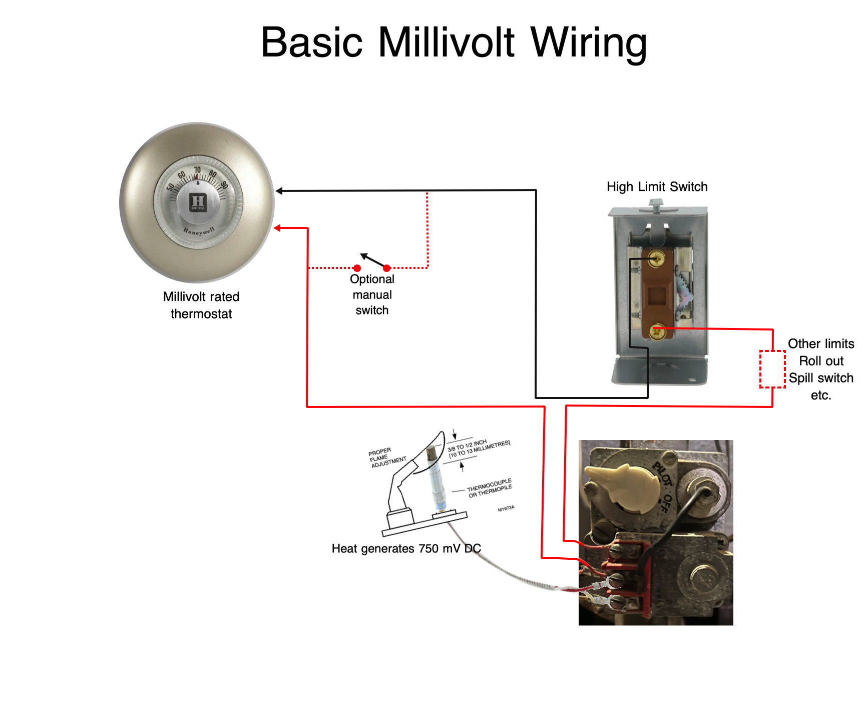
If there was only one thermostat for the entire home, the thermostat would be rated for 750 mV like the Honeywell T86A pictured in the diagram. If that is the original high limit control that should also have mV rated contacts.
In this set up you could connect this boiler to a gravity radiator system and in the event of a power failure you can still have heat. the 750 mV is generated by the pilot flame touching the Powerpile pilot generator. No other electric source is in the diagram.
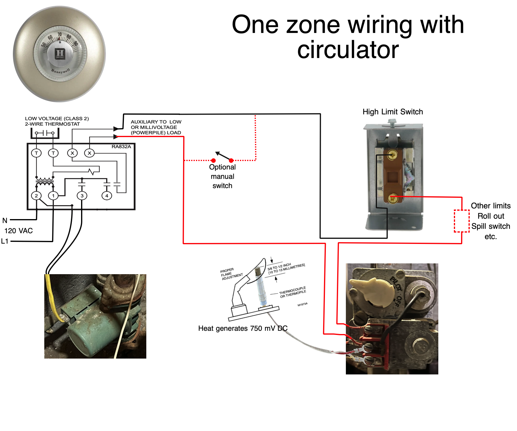
If your boiler was equipped with a circulator from the factory there would have been a switching relay similar to the Honeywell RA832A. There are several contacts on this type of relay but the most important set of contacts are the ones connected to the X X terminals. Those contacts are rated for 750 mV. This is very similar to the R8845U relay that you are now using.
If you try to use other contacts that are rated for up to 240 Volts AC, you may find that those contacts prove to cause problems with Millivolt circuits because there may be some resistance to the flow of electricity that 24 V., 120v., and higher will overcome with no problem. The 750 mV current may not always make contact and leave you without the gas valve operating as expected. There is one benefit to this design, if you loose power, you can turn on the manual switch on the back of the boiler and get the gas burner to fire. this will cause thermosyphoning, commonly known as gravity heat, to circulate. This may not be as much heat as the circulator pump will move, but it will protect your home from freezing up and having burst pipes.
The next diagram illustrates how YOU should rewire your system to avoid the problems associated with millivolt gas valve and zone valve end switches that may not be rated for 750 mV.
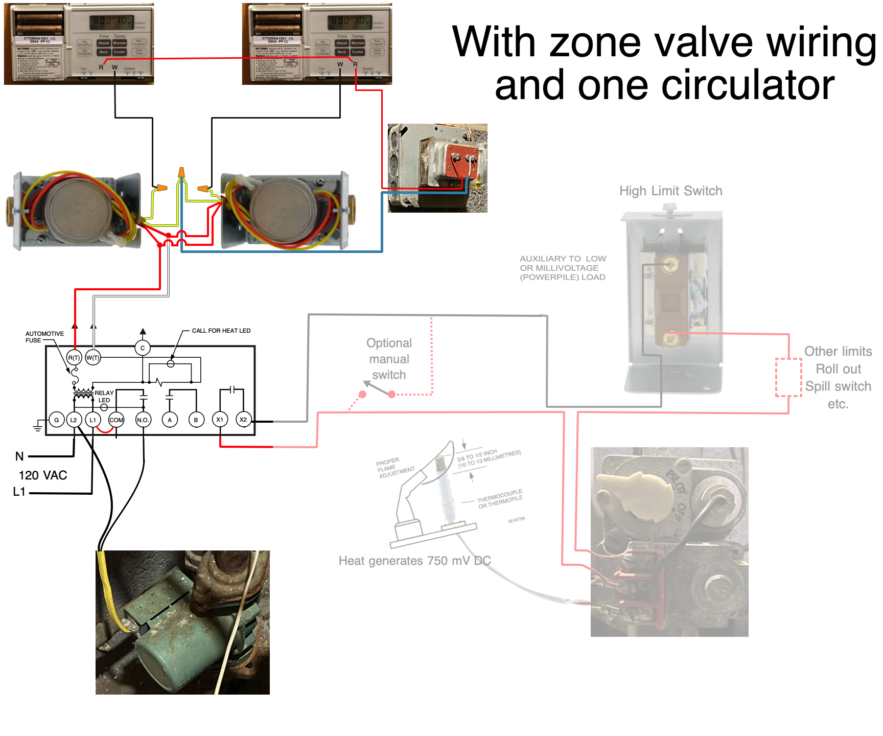
You can clearly see the 24 VAC transformer connected to the zone valve circuit. Do not use the thermostats to operate separate R8845U relays. You want the thermostats to control the zone valves as the manufacturer of the zone valve intended. Those thermostats will operate the zone valves and the zone valve end switches will operate the one R8845U relay that has the ability to power the circulator and the X X terminals to control the mV gas valve. If you do the zone valve wiring this way, you can still use the gravity heat in a power outage by manually opening the zone valves and set the manual switch on the rear of the boiler to MAN.
To make it easier to follow, I have faded the wiring that you already understand from the previous two diagrams.
In order to make the Zone valve wiring a little more simple I will do the same fade out to isolate each circuit here?
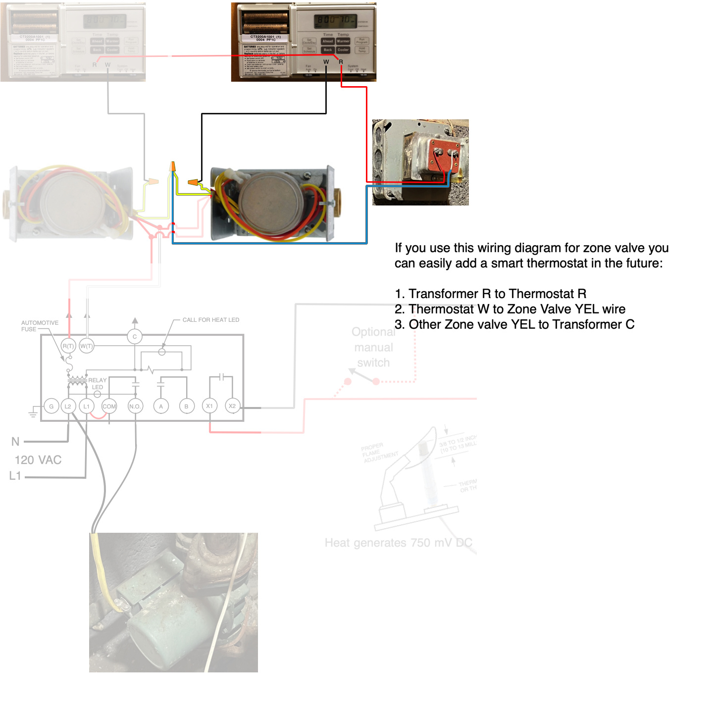
If you follow this wiring diagram for all zone valves then you can add a smart thermostat that requires a C terminal in the future with no problem:
- Transformer R to Thermostat R
- Thermostat W to Yellow wire on the zone valve
- The other Yellow wire on the zone valve to C on the transformer
Follow the same wiring on all other zone valves.
When the power side of the zone valves are done and operating and tested. you can move on the the end switch side of the zone valve.
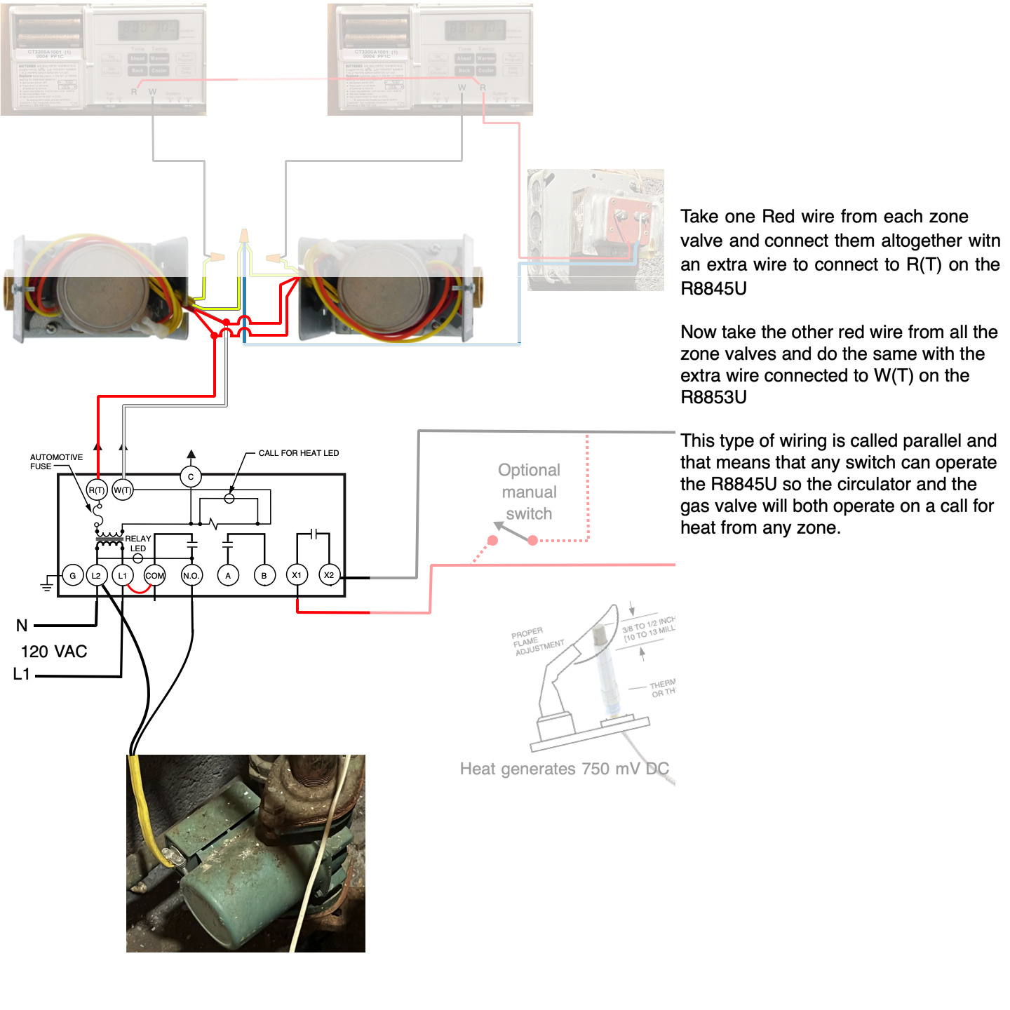
Take one Red wire from each zone valve and connect them altogether with an extra wire to connect to R(T1) on the R8845U
Now take the other red wire from all the zone valves and do the same with the extra wire connected to W(T2) on the R8853U
This type of wiring is called parallel and that means that any switch can operate the R8845U so the circulator and the gas valve will both operate on a call for heat from any zone.
Since I have on way to know how well versed you are in electrical circuitry I took the time to build each section of the boiler system you have one step at a time. I hope this helps you to understand your system better.
Mr. Ed
Any Questions?
Edward Young Retired
After you make that expensive repair and you still have the same problem, What will you check next?
1 -
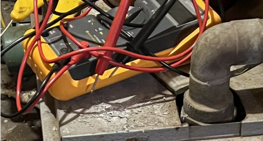
@EdTheHeaterMan I did notice a fluke meter, so hopefully the re-wiring will be fairly easy for @bkirnum.
When the control system is built out as described above, it usually easy to understand and troubleshoot if ever needed. Each stage can be analyzed for proper functionality. A jumper wire is all that may be needed. A multi-meter is handy also, to verify the power for each stage is present and other testing depending on your troubleshooting style.
I would keep a spare Powerpile handy.
 National - U.S. Gas Boiler 45+ Years Old
Steam 300 SQ. FT. - EDR 347
One Pipe System 2
2 -
After wiring up the 24V circuit as recommended the system is working. I had also forgotten to check the pilot which had gone out at some point. Either thermostat can again turn on the zone valve, pump, and furnace for the proper zone.
Thanks so much for the help!0 -
" Trying to understand wiring for heating system "
Good that it is now working.
Hopefully now you understand more than you ever really wanted to know about your boiler's wiring.
National - U.S. Gas Boiler 45+ Years Old
Steam 300 SQ. FT. - EDR 347
One Pipe System1


Categories
- All Categories
- 87.5K THE MAIN WALL
- 3.3K A-C, Heat Pumps & Refrigeration
- 59 Biomass
- 429 Carbon Monoxide Awareness
- 124 Chimneys & Flues
- 2.2K Domestic Hot Water
- 5.9K Gas Heating
- 118 Geothermal
- 168 Indoor-Air Quality
- 3.8K Oil Heating
- 78 Pipe Deterioration
- 1K Plumbing
- 6.6K Radiant Heating
- 394 Solar
- 15.9K Strictly Steam
- 3.5K Thermostats and Controls
- 56 Water Quality
- 50 Industry Classes
- 50 Job Opportunities
- 18 Recall Announcements