Best Of
Re: Undersized steam supply causes carryover, right? Right??
I believe that's exactly his point, right now.
 ChrisJ
Re: Understanding Hydronics
There's no substitute for getting out and working on as many systems as possible. Which means finding someone experienced under whose supervision you can work until you get some experience.

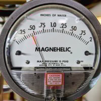
Re: Is this brand new gauge defective?
I went to the watts.com website and found a page to email them, so sent the following to Technical Support (closest category they had). They don’t have any way to send pictures, so I sent a link to this forum thread. I’ll see if they respond, and start the process to return this one too. I can’t believe things have gotten this bad.
“I have received two defective Water Pressure Test Gauges, model IWTG. Ordered from Watts Store on Amazon, then a replacement sent that is also defective.
I started a thread about it, including pictures, at https://forum.heatinghelp.com/discussion/203112/is-this-brand-new-gauge-defective
Could you please let me know if I should return this second gauge and ask for another replacement, or whether it is impossible to get a working gauge from Watts on Amazon?”
 JeffGuy
Re: Counterflow steam system
Where do you drain/purge the water from the main at??
How about pictures…….the usual request…..floor to ceiling….all sides?
 JUGHNE
Re: Counterflow steam system
agree that’s why I’m here. Feel like I’m close. Most are saying never seen a system like mine so of course it’s going to take a lot of questions and back and forth. I guess I should have went with the 50s ranch with hydronic heat!
 JoshP
JoshP
Re: I'm getting solar panels. I'll let you know how it goes in this discussion thread.
Interesting that the went to the roof edge on the left side. I thought code required a walk path around the entire array. Maybe two sides is all that is required?
It passed inspection, so it must be code compliant, and they maximized the roof area.
 hot_rod
Re: Undersized steam supply causes carryover, right? Right??
I really enjoy your videos. Is it practical to replace the bushing coming out of the boiler so that the supply starts out immediately reduced down? That would bring the higher velocity down closer to the steam chest.
 Eastman
Re: Undersized steam supply causes carryover, right? Right??
Your experiments are fascinating and entertaining… but, forgive me if I look at it from the standpoint of an engineer… you have too many variables involved to draw general conclusions, since your are not varying some of the more important ones.
As I have said, residential and small commercial heating steam systems are incredibly forgiving. Arrangements work just fine which seemingly have no business working at all, and which violate many guidelines. In fact, there aren't that many guidelines which really are all that critical.
That said, the guidelines and general rules of practice are of value, as coming reasonably close to them almost guarantees the system will work, at least "well enough".

Sizing steam radiators
: I need help sizing a steam radiator. the current radiator in the room is 16 sections, 26 inches high, 5 regular tubes. I'm trying to find out how many BTU's this radiator is and I want to replace it with the highest radiator available so I can maximize wall space. please help
thank you
 BDRaff
Re: Radiator vent loudly sucking air INWARD after boiler turns off
You explanation IMHO is flawed. It's a matter of Physics that when the steam collapses the air has to get back in the system.
Do you agree?
Nothing in the statement you posted:
"It has to do with do you understand what is going on and what methods to correct it. If the pressure is high, lower it. If the vent is not operating properly, test it and replace it with one that was tested. If you need a steam control device to operate the boiler instead of a thermostat, get one. Basic problem solving:"
gives any information or tells anyone how to fix the problem we are talking about.
"It has to do with do you understand what is going on?
Yes, I do, the change in volume from steam to condensate is 1700x
"If the pressure is high lower it"
I agree low pressure is better in most cases. But as @ethicalpaul mentioned this has 0 to do with steam collapsing and the resulting vacuum.
"If the vent is not operating properly, test it and replace it with one that was tested."
Vents vent air and let air in. They close when they sense steam. They should not leak water. They should not pass excessive steam. That's all there is to it.
There is no mystery here. Air has to get back in the system when the boiler cycles off.
