Best Of
Re: Triple Aquastat
@Alan (California Radiant) Forbes
I got called in to start up an oil boiler once where the plumber installed a boiler for heat but it had an unused tankless coil in it so it was hot all the time.
Instead of replacing an expensive aqustat I installed a relay in front of the aquastat breaking the 120 to the aquastat with a relay pulled in from the thermostat and jumping T & T in the aqustat.

Re: Undersized steam supply causes carryover, right? Right??
Steaming boiler and a Shop-Vac, what could go wrong…
 109A_5
Re: Air in the heating loop
Thanks, I can be a drain at the end of the farthest baseboard and see the pressure. Was think of doing that anyway to try and purge form the 4th floor as a push and pull.

Re: Setback tstat or constant 24 hr temp as it relates to interior furnishings.
It looks like you have a ~130KBTU/hr boiler, which is probably extremely oversized for your actual heat loss - one advantage of such an oversized system is the rapid recovery from setbacks. Depending on what your control setup is, you could have the heat pump maintain steady-state at either 62F or 68F, but use the boiler to quickly recover from the setback. With programmable thermostats you might be able to do something like:
- Boiler and heat pump are 62F overnight
- At 6AM, boiler jumps to 68F and starts pumping out heat. Heat pump is still at 62F.
- At 8AM, heat pump jumps to 68F (and the house is probably already at 68F), and boiler falls back to 66F so that it only kicks on if heat pump can't maintain heat.
 fentonc
Re: Setback tstat or constant 24 hr temp as it relates to interior furnishings.
There are two questions here:
First is, does a setback cause a house to lose less heat? The answer is yes. The amount of heat lost to the environment is determined by the difference between the inside temperature and the outside temperature, with a setback the inside temperature is lower some of the time and loses less heat.
The second question is whether the setback will save you energy. With a combustion appliance the answer is yes, a BTU is pretty much a BTU. But with a heat pump it becomes more complicated, because a heat pump uses a variable amount of energy to produce a BTU. First, the colder it is outside, the less efficient a heat pump is. So if you're running the heat pump less when it's warmer and more when it's colder— like you would if you turned the thermostat down when the house was unoccupied during the day — the setback may not save you anything. Some heat pumps have supplemental heat, when the controller detects that the heat pump isn't meeting the heating load it energizes resistance heat to supplement the heat pump. The supplemental heat is much less efficient than the heat pump, typically about half as efficient. Often the way the heat pump detects whether the heat pump is meeting the heating load is by comparing the thermostat set point to the inside temperature. In such a system, a setback will guarantee that the supplemental heat runs regularly, which will increase your energy usage.
Generally the recommendation for heat pumps is not to use the setback.

Re: Air in the heating loop
I capped off the spirovent in hopes that it was sucking in air. Did a purge same story. So tired of chasing this problem.
Re: Used Roth Oil Tank Installation
jut get a new tank and do it right.
it’s December you’re not going to change the boiler or do a conversion to gas this time of year
 pecmsg
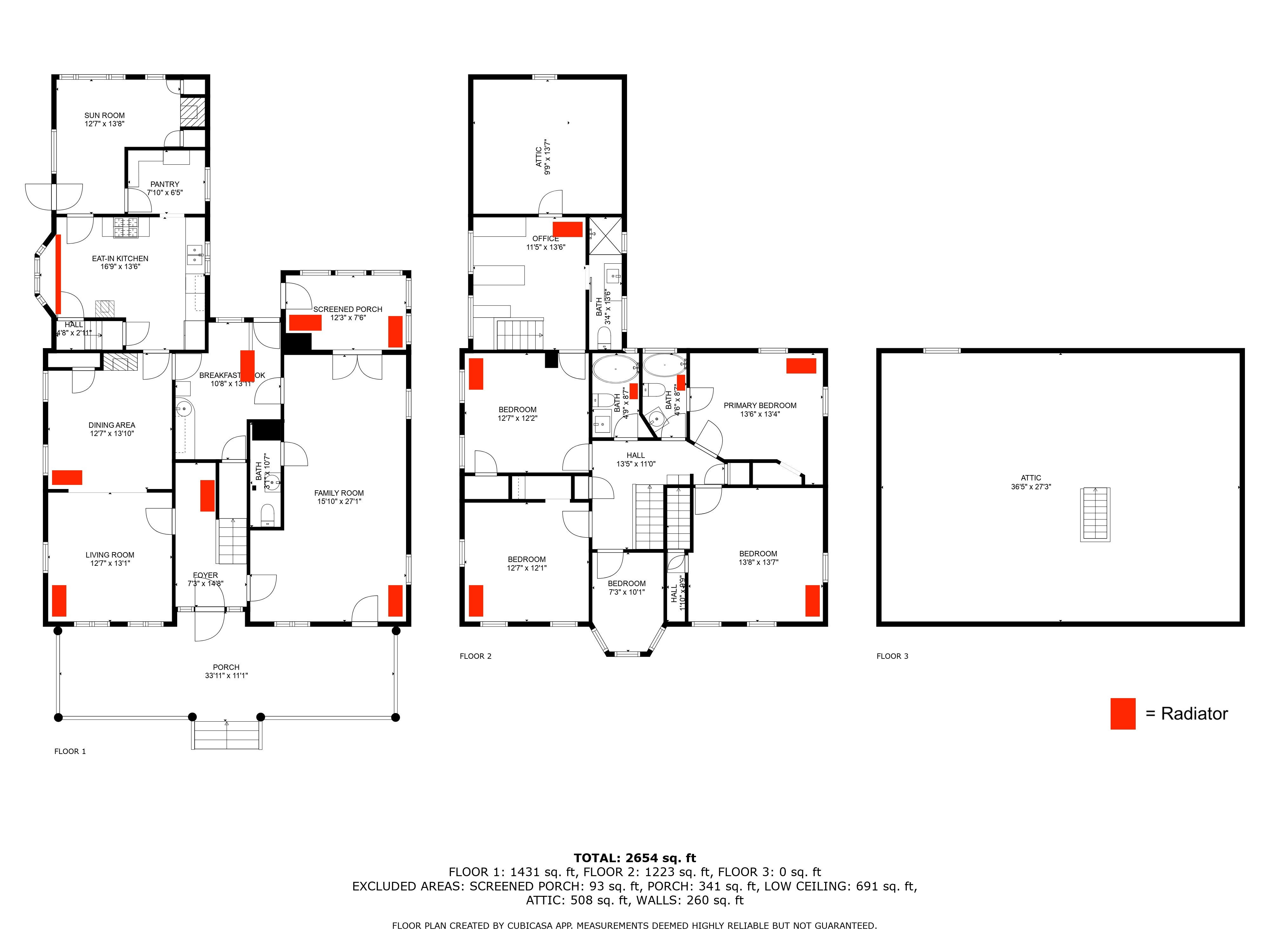
Re: Heating and Cooling Options for 1850s Greek Revival New York
@JUGHNE Thanks for the reply! The radiators are hot water. I've attached a few pictures of the boilers and radiators.
There is a full basement below the original house but not below the 1930s extension (kitchen in the floorplan).
 lchamb
Heating and Cooling Options for 1850s Greek Revival New York
Hello Everyone,
I recently purchased an 1850s Greek Revival farmhouse knowing most of the mechanicals in the basement needed to be replaced.
I had a few HVAC companies out to give quotes and quickly learned that no one agreed on the right approach for the house, making comparing quotes difficult.
Instead of replacing the mechanicals 1:1 I want to rethink how the house is heated and cooled.
My friend’s father-in-law, who is a retired plumber, shared this site with me and I wanted to post my situation and get some feedback and advice.
The House
~2,850 square foot 1850s Greek Revival farmhouse in Columbia County, New York.
Main house is two stories with a basement and attic. There is a two-story 1930s extension off the back that has a mudroom and kitchen, with an office and storage on the second floor. No basement or attic over the extension.
At some point in the past the house was split into two units, and there are still two of everything in the basement (boilers, water heaters, well pumps) for the “left” and “right” halves of the house. There are two Nest thermostats that control left and right, both upstairs and down.
Main heating is two oil fueled boilers that heat 15 radiators upstairs and down. One of the boilers is an ancient HB Smith (48 years) and the other is a 10 years old Buderus. The two oil tanks are rusting single-wall units and need to be replaced. There are also two wood stoves, a gas fireplace, and an electric fireplace.
There are two older hot water heaters. The first is 50 gals 27 years old Richmond and the second is 40 gals 18 years old Sears Roebuck.
The previous owners had a few window A/C units in the main bedroom, the office, and one of the living rooms.
Goals
My original goal: to replace the oil tanks with natural gas and install whole-house A/C and humidity control. I have moderate to severe allergies and was also looking into technologies that affect air quality like heat recovery ventilators and HEPA filters.
Originally I thought to take all of the radiators out and install forced air heating and A/C in the attic and basement. I’d seen some old houses do this during my housing search, but almost everyone I talk to advises against taking out the radiators.
The other route is mini-splits but I find these ugly and the installers said I would need a lot of them for the layout of my house. I didn’t get a specific quote but one contractor said it would be north of $100K+.
For what it’s worth, my friend’s father-in-law said he would install Viessmann gas condensing boilers, with one domestic hot water tank, in the basement and leave all the radiators alone, and install a Spacepak system in the attic for A/C in the bedrooms and supplemental heat.
If you read to the end thank you!
lchamb
