Best Of
Re: taco sentry zone valve
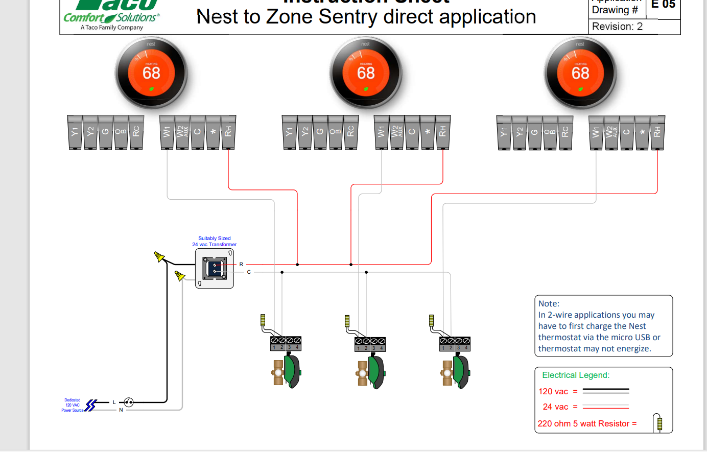
@heatguy24 Please see below. The resistor would go across the 2 power terminals on the Zone Sentry valve actuator labeled C-W/y
 SteveSan
Re: Radiant flow not pushing fast enough
I would purge air from the loops and add a halfway decent microbubble separator. You have short loops, and not many of them, the smallest pump should still be overkill, if its not flowing look to the system, you have no lack of pump on this system unless your loops are a whole lot longer than the mention 200'
 GGross
Re: Triple Aquastat
why are there 3 transformers (and probably a 4th for the indirect that we can't see)? it is probably time to pull all the wires out and start over before you condemn any controls. it looks like someone added the indirect with as little effort as possible so there is now wiring going everywhere. figure out what goes to the t-stat and the aquastat in the indirect and piece it together from there.
 mattmia2
Re: Radiant flow not pushing fast enough
(UPDATE) so the Winter is here. My brother helped me move the circulator pump just after the mixing value which was prescribed by the majority of responses. The floor is getting the necessary hot water to warm up the zone. I had to change the taco pump aswell. The old pump was pulling hot water through the manifold but didn't have the power to push all the loops, all the way through and back to the cold side of the manifold. The pump possibly got burnt up on the old setup before moving it. I now have 120⁰ going out and approximately 90⁰ coming back.
Thank you all, Happy Holidays

Kudos to tech support at Rinnai
I just want to give a thumbs-up to Rinnai for their tech support. I installed an new "I"series boiler — 120MBTUH (heat only w/ indirect) as a replacement for a Buderus GB142. It wasn't "playing-well" with Honeywell 'round' (no mercury) thermostats. So I put in a Taco 6-zone pump controller as an interface. All is well. Thanks to James and Mark at Rinnai….ON A WEEKEND!
 psb75
psb75

Re: which boiler parts should be preemptively replaced?
When I sold a lot of Crown Boilers there was this kit I purchased to service the ModCon boiler they purchased from Europe and rebranded. After sell about 6 of them, I purchased the kit. it had an ignitor, flame sensor, gaskets for the heat exchanger and flue collector, the electronic control that operated everything, some temperature sensors that would clip onto the pipes, and a flue gas temperature sensor that was pushed thru a high temperature rubber gasket of some type. How many circulators are on your system? are they all the same? If so, I would get one of those. With about 15 boilers of that model total, I only used one control board and one flue temperature sensor in the 7 years after I started using that boiler until I retired.
That Kit went with the new owner of my customer list. I'm not sure he knows he even has that kit if parts are needed.

Re: Copper for condensate pipes? Your opinion
Matt and I, like many of you here, are at the age where we're replacing boilers in homes and buildings for the second or even third time. It's fun to see these little time capsules of how we used to do things compared to what we might do differently now. Copper wet returns have been standard practice on my installations for decades with no developing issues. Electrolysis at the point of transition is absolutely not a thing in these cases either. In fact, the conditions that allow electrolysis and galvanic corrosion I think are the most misunderstood concepts in the piping trades.
I will definitely concede that those of you working in parts of the country where water quality is an issue may have different experiences than we do here and for perfectly legitimate reasons.
 JohnNY