Best Of
Re: My New EK-2 Boiler Isn't Meeting Efficiency Expectations. Any Help Appreciated!
Thank you for your post, @wjcandee , and for everyone's comments.
The first point I'll make is if you have any concerns that you feel are not being addressed to your satisfaction, you should contact us directly at (908) 735-2066 and ask to involve your territory manager. This will clear up many of the questions you posed and allow for a prompt resolution. We should have our territory manager and your dealer talking directly about your concerns.
You high water volume system with cast iron radiators has low mass/high mass piping installed (primary/secondary piping), which is excellent.
Regarding efficiency, give the system a chance to work while properly installed. It sounds like you've ironed out some issues so you should be in good shape after our territory manager reviews your job with the dealer.
Here is some background on energy savings, which may or may not be applicable to your situation (I'll use an oilheat example). When we analyze savings, we usually look for two years of prior history and at least one year afterwards. It's difficult to gauge when oil tanks are sometimes completely filled and sometimes not. Over the course of a year and with the delivery company intentionally filling the tank at the beginning and the end of the year will allow much more accurate estimates. It's also important to realize that we need a good "starting fill" to estimate fuel consumption properly. For example, if the tank is completely filled on June 1, the boiler is installed September 1, and the tank is then completely filled again November 1, there are 3 summer months of usage under the prior boiler, so we can't start estimating until deliveries are made sometime (preferably a year) after then November 1 fill. We then normalize the savings using heating degree day data from a local weather station.
Analyzing a mix of heating and hot water fuel use over a short period of time even with degree day data is not a preferred way to gauge performance. You have an EK2, so you will have a large heating load so this may be even more pronounced.
The primary/secondary (low mass/high mass) zone valve opening and closing is protecting the boiler from condensing. The burner will run without shutting off during these cycles. This does not reduce the overall boiler efficiency, but improves comfort and protects the boiler. Here's why: The circulator on the primary loop (which goes out to the radiators) continues to run with high enough flow that the radiators will typically heat much more evenly. Because the primary loop circulator continues to run, the heat distribution is much more even (as compared to a typical boiler where the heating circulator would turn off when the boiler temperature dropped too much from cold returns; this would "pulse" heat out and causes near radiators to heat rooms more than more distant radiators).
There is usually a ball valve on the return of the injection zone, and throttling this somewhat will reduce the number of zone valve cycles. This is a specific setting for a given primary/secondary loop, and once it's set it does not need to be moved again. Nothing hurts the efficiency or the boiler if this is not done, but if it is your preference, it could be adjusted to reduce injection zone valve cycles. Throttling too much could cause the burner to turn off from a high boiler temperature from too much bypassing water earlier than it would with less throttling.
Best,
Roger
 Roger
Roger
Re: Steam Sizing Question.. what would you choose?
I'm not a steam guy, but does the current "original" boiler in question still actually function? If so, can you go back to the house and check how the system is performing for yourself? Then you would know if all the rads are getting warm enough or not. Instead of relying on the guy that "doesn't remember"
 gpjazz
Re: How Do I Connect This Wire?
I'm often asked about VENT DAMPER INTERNAL WIRING
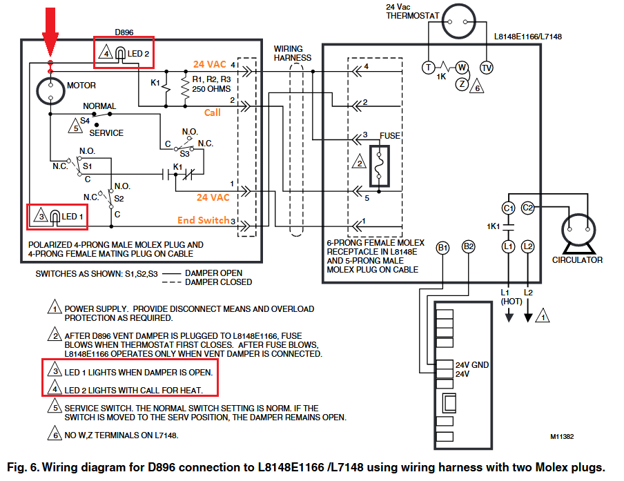
The best diagram I have on the internal of the auto vent damper, and this is from a long time ago (not the current Fields/Effikal version) is this one:
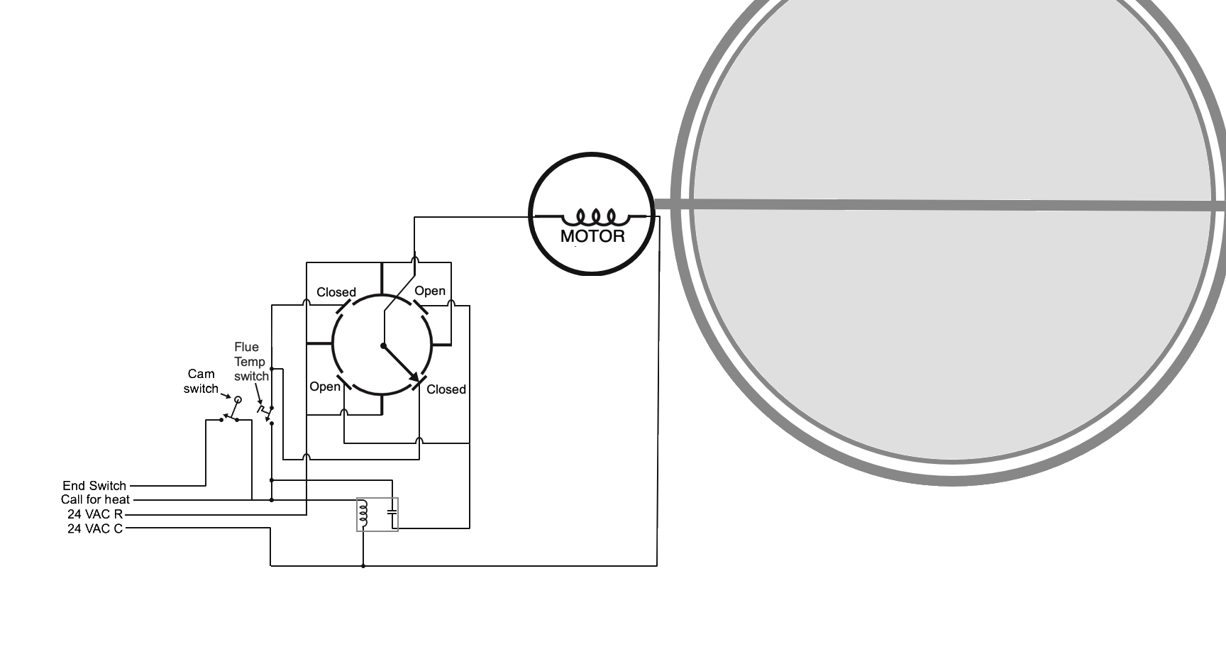
The motor stops at each 90° turn of the motor. 90° to open, 180° to closed, then 270° to open, then 360° = 0° to close. There is constant power needed to operate the motor to close the damper after the call for heat is satisfied. @EBEBRATT-Ed has the correct wiring description
- Constant hot 24v from transformer "
R" Black wire to #1on the damper - 24 volt common from transformer "
C" Green wire to #4on damper - #
2on damper yellow wire to 24v on ignition control (starts burner) - yellow at damper. Starts at "
R" red on transformer through limit and operating controls to damper #5
There is a 6 Pin Molex on the control that the damper is attached to in order to prevent Bubba from placing the jumper plug back on the control while there is a broken damper installed in the flue connector between the boiler and the chimney base. There is a fuse placed between pin #3 and #5 on the Molex mounted on the control. The factory installed jumper connects pin #2 and #3 in order to complete the “End Switch” circuit when a vent damper is not used. when a damper is connected the 6 pin has on more wire that @EBEBRATT-Ed did not include. the green wire (24v. hot or R) is connected to pin 4 and pin 3
Imagine Bubba at the service call: This has happened more than once before this wiring design was made standard. No heat and the vent damper cam switch (end switch) is the problem. So, Bubba jumps the switch to get the burner to operate and locks the damper in the open position (because he is too lazy to remove the damper) and you have heat. Later someone sees that the damper is locked open and does you a favor by removing the bracket that is keeping the damper from closing in order lower your fuel bill and save you money.
The next call for heat the damper gets stuck closed but the cam switch is jumped and the burner operates with a closed damper. The next day there is a big news story about carbon monoxide poisoning. In the 1970’s this was not just a one off story but something that happened enough times to cause a new standard wiring design using that special connector cord with a 4 pin on one end and a 6 pin on the other end Here is how that works.
- No damper = jumper from
2to3 - Add a damper and the first time the damper opens power gets sent to
5and3 5powers the burner circuit and3gets a direct short to the transformer and the fuse blows between5and3- Now the jumper from
2to3will no longer work on that control
Now if the factory installed "No Damper" jumper is put back in the control, after a damper has been installed and wired in, it will no longer work since the fuse between 5 and 3 is blown. This keeps Bubba from just putting the jumper on the control to get heat without doing some real serious rewiring and maybe even removing the damper from the flue connector pipe.
I need to add this one to my "How Do I connect This Wire?"
How it works one step at a time
Take each circuit one at a time if you want to understand it.
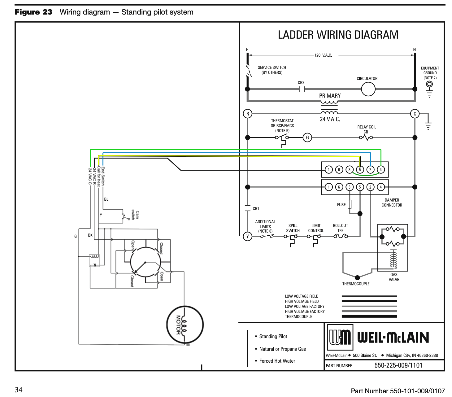
Everything in Red is powered and the blue is the return path to the transformer. The purple Is the path from the rotary switch arm to the hot side of the damper motor.
The switch arm in the closed position has no power until there is a call for heat
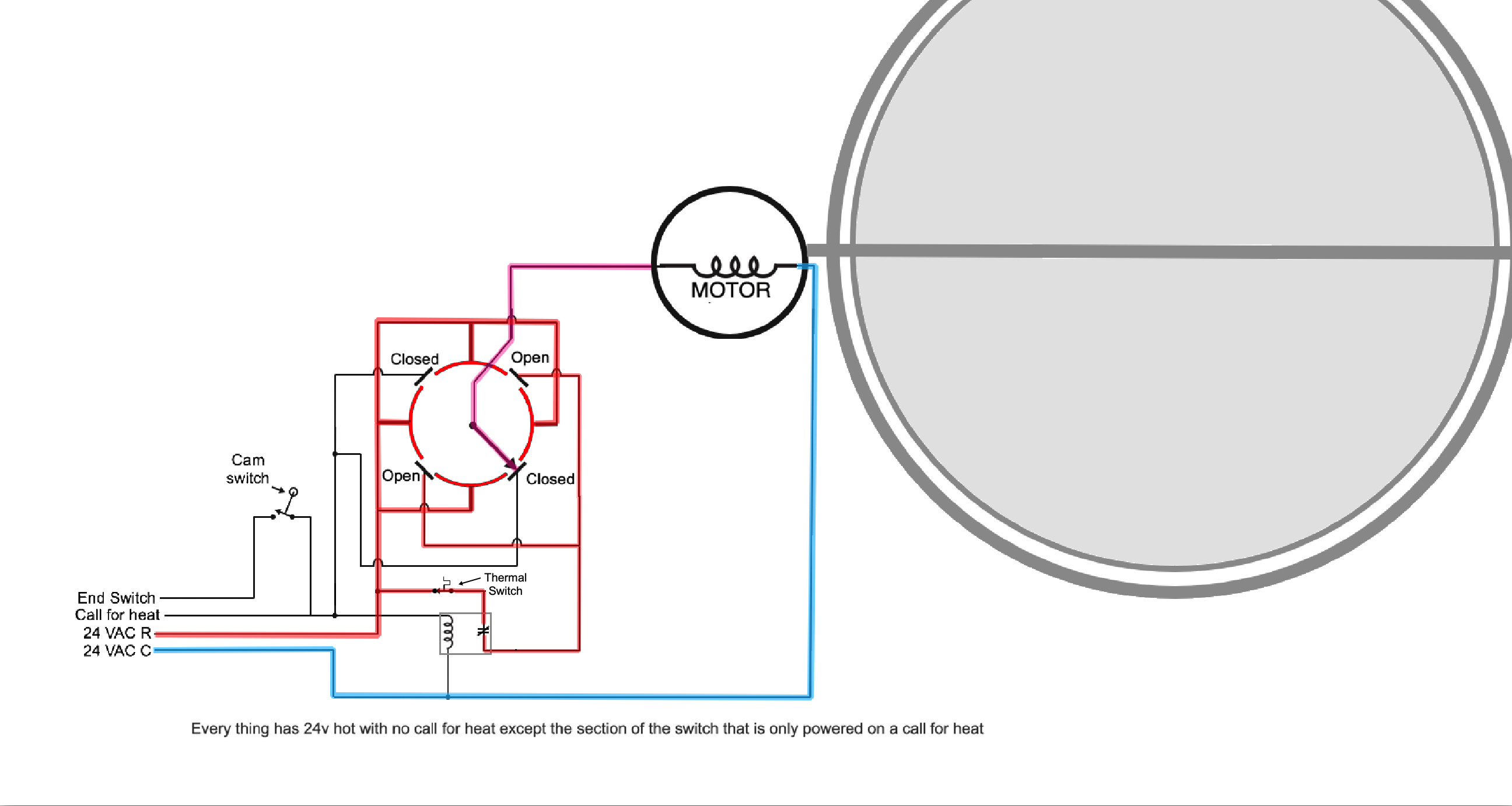
That call for heat causes three things to happen (See Orange wires). The Closed contacts get power to start the motor. A relay coil causes the power to the Open section to the rotary switch to lose power and the motor then reaches the “Always Hot” portion of the rotary switch so it continues to operate until it is completely open.

When the motor reaches the full open position the motor stops since there is no power to the Open contacts on the rotary switch. Also the Cam Switch (End switch) closes sending power to the burner circuit (Green wire).
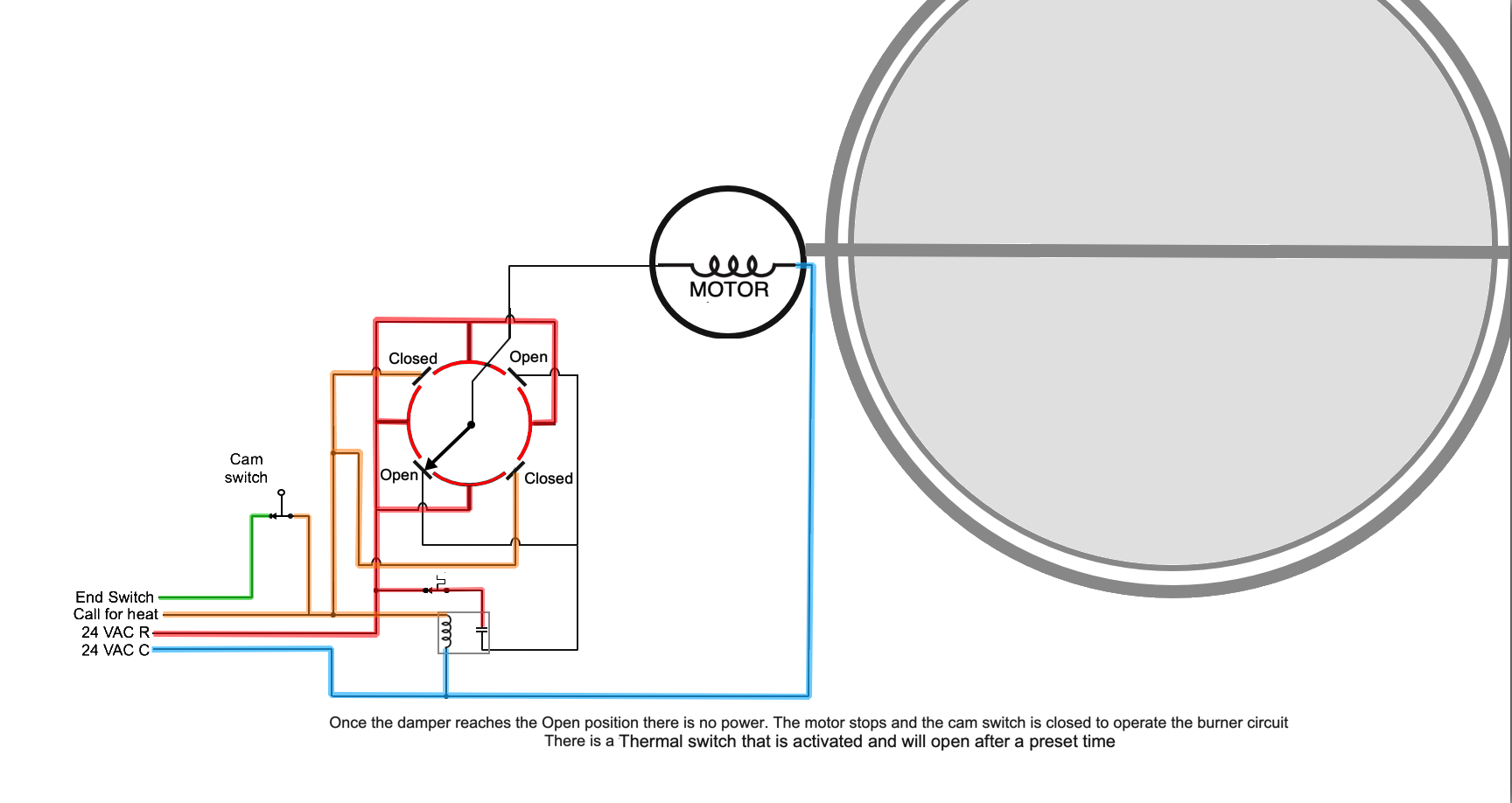
The burner operates safely with the damper open. Eventually the call for heat or a limit stops the burner.
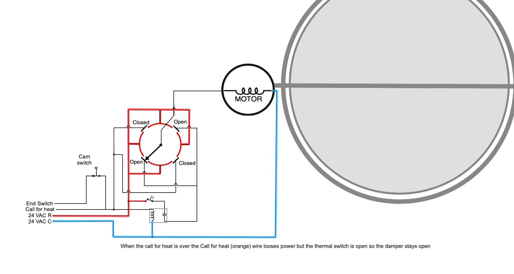
The orange call for heat looses power and the green to the burner looses power but the thermal switch may keep the damper open for a time in order to clear out the byproducts of combustion from the boiler or furnace.
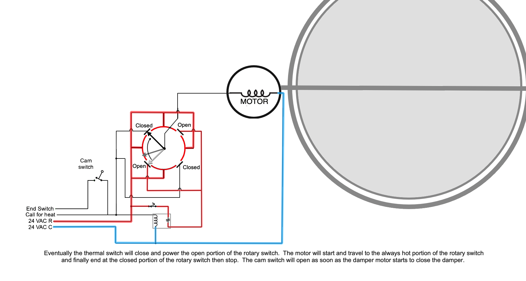
Eventually the thermal switch will close and power the open portion of the rotary switch. The motor will start and travel to the always hot portion of the rotary switch and finally end at the closed portion of the rotary switch then stop. The cam switch will open as soon as the damper motor starts to close the damper. EBEBRAT-Ed found this diagram in the instructions from 1995 and 109A_5 fixes the error on the diagram

Re: Radiant Heat. Should I raise the temp?
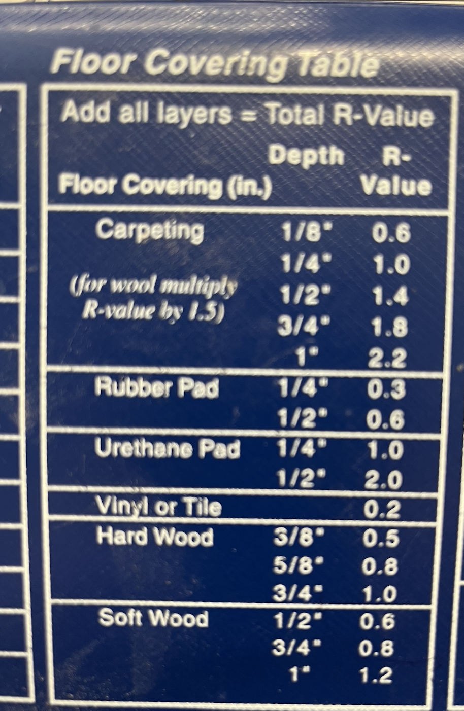
Carpet with pad below? That could be a tough go for radiant heat. Here are some examples of R-value for floor coverings
The slab surface temperature is what you want to know and then see what the wood flooring manufacturers allow. If it is glue down flooring, check the adhesive limitations.
Was a heat load calculation and design done for the system? That would show how the carpet dictates the floor btu output.
That 120- 90 is a wide delta, 10- 15 is typical for residential home radiant. It depends on when you measure that ∆. If you could increase the flow rate the floor surface would even out, be more consistent across the surface and may helps.
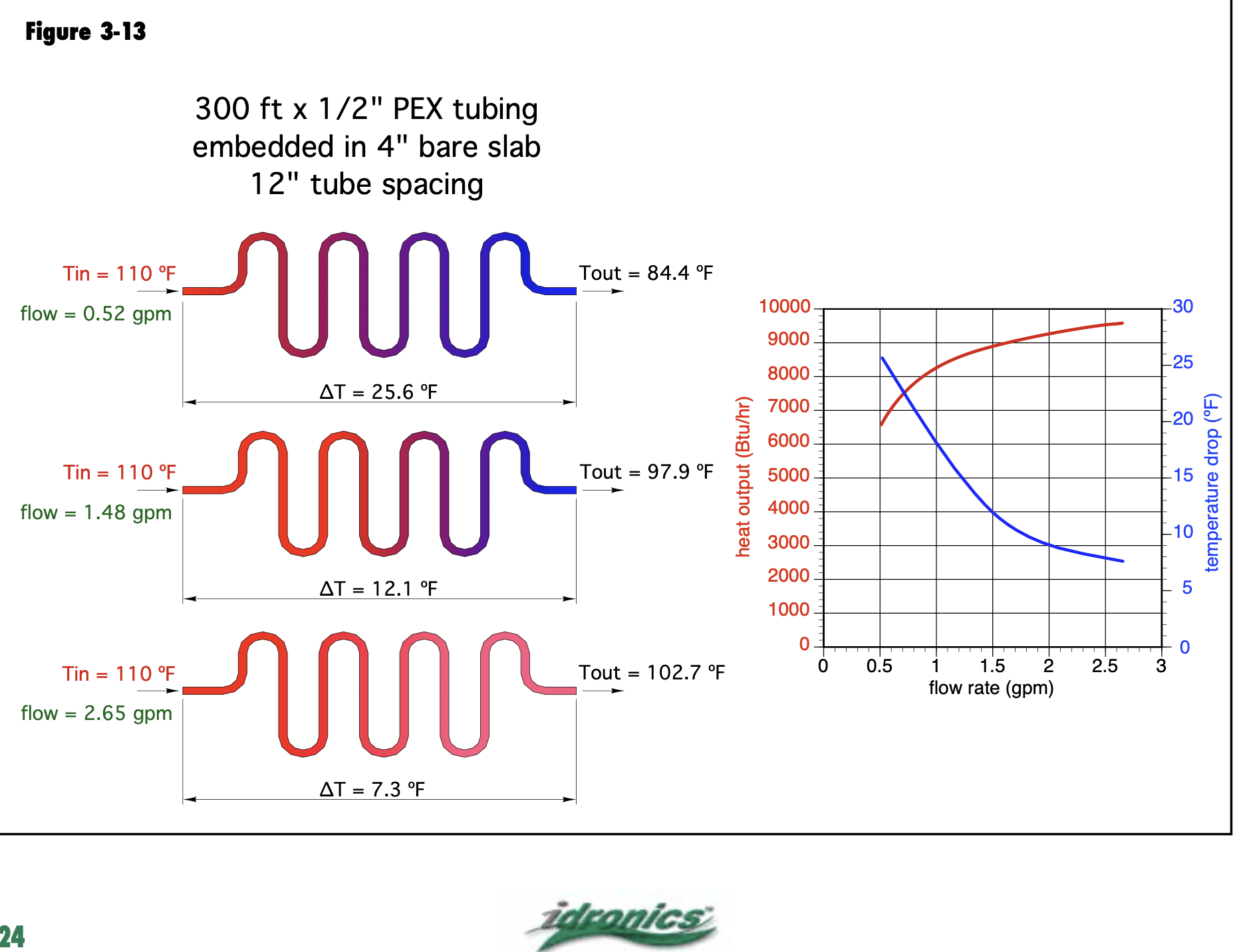
Increasing temperature or increasing flow will get you more btu/ ft output. This graphic shows the result of the loop temperature from beginning to end as flow is increased, same SWT.
There is a point of diminishing return, from .5- 1 gpm you see a good boost, the red output curve starts to flattens at around 1.5, it is may not be worth the pumping power to get higher flow rates for minimum increase. You have flow meters on the manifold 1/2" loops you could push .75- .80 gpm maybe, through the under-heating loops.
How long are the loops? What tube spacing? Plain water in the system? Your manifold pump will be the limit to what you can actually flow. It's nice to use a multiple speed circulator to get some adjustability.
You want to measure the loop delta after it has been running for a period of time. When the supply and return temperature stabilize, that is thermal equilibrium, measure at that point.
The delta is ever-changing in hydronic systems it is not something that you can "set" the load at any given point in time, how much heat the loops dissipates, that determines the operating delta.
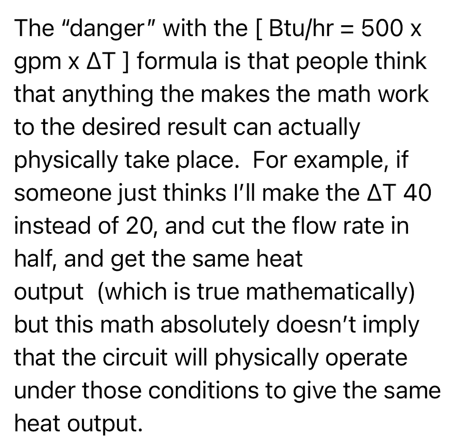
Trust the onsite measurements to determine the output, the universal formulas can deceive as my mentor explains it.
 hot_rod
Re: Single pipe vented steam heat
draining and replacing brown water without addressing pH level is chasing your tail.
The fresh water just makes more rust faster
The tech is right. But I say you shouldn’t need more than 5 gallons per season

Re: Williamson GSA-100 Steam Boiler Tappings
The WM block, and the Williamson block, are exactly the same. WM offers the tankless coil option. Williamson does not. But on their typical standard boilers, the blocks are exactly the same.

Re: Williamson GSA-100 Steam Boiler Tappings
Yes. They don't approve its usage, but it is there. The only reason that it's not approved, is because they need to differentiate themselves a bit from Weil Mclain
Re: Attached EDR vs Boiler SF of steam
If the radiation can't keep up it doesn't matter how big you make the boiler it'll just keep cycling on pressure.
What pressure was your boiler running during this event?
 ChrisJ
Re: Rehashing the old Williamson vs Weil McLain comparison, and new boiler specs
I am partial to the vomiting part. Then you know for sure its a bad boiler.
