Best Of
Re: Air vent Requirement on Steam Main Line
The first picture looks to me like a feeder pump to return cond water to the boiler.
The second picture looks like a drop header with the drip F&T trap going into the feeder pump tank.
You may have a one pipe system and are the traps you refer to the ones at the tank?
I would call them end of main float & thermostat (F&T) traps going into the tank also.
 JUGHNE
Re: Air vent Requirement on Steam Main Line
Yes, I have a one-pipe steam system and the traps are near the tanks only.

Air vent Requirement on Steam Main Line
Hello,
I am working on this building (one-pipe system) where I came across this piping arrangement located in the boiler room itself. So the steam header is branched into many main steam lines and one of the lines is shown in the pictures attached.
We can clearly see the steam pipe coming from the right side of one viewing the picture. it separates into two risers and then we can see the condensate lines pitching downwards towards the left. Do we need an air vent on this location? Because I was not able to see one.
Fyi, this building has steam drum in it's distribution system which has steam trap feeding to feedwater tank.
Thank you.
Regards,
Re: Unrecognized return vent
they have another thread with this system. that is what they have.
 mattmia2
Re: Unrecognized return vent
If each radiators return is piped individually to a wet return then you need no traps. You should have an air vent large enough to vent the air from the supply run out through the radiator and the return line and the air vent should be located at the top of the riser where the return drops into the wet return

Re: Unrecognized return vent
early vents used a carbon rod that would expand in the steam, you might have some form of that.
mattmia2
Unrecognized return vent
Hi,
I would like to identify the vent found on my radiator returns. See pics below.
Note: in the first pic, the second bump is actually the L of a second vent behind the first.
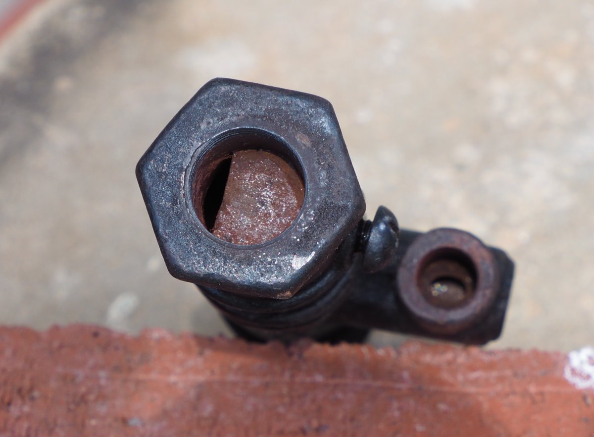
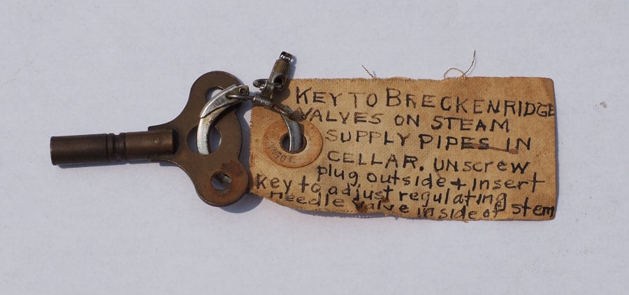
EDIT: Found adjustment key
The vent has no identifying marks of any kind. It is 6" long. The bottom threaded hole is slightly more than a 1/4 NPT. The opening on the L is threaded. The L hole communicates with the bottom. However, on heating the vent, it did not close off air (perhaps broken). There is a rod and brass cap of the L; the rod has a threaded section, but sits loose in the inner hole. The the screw on the body is removed, the hole communicates with both the bottom and the L; when tightened, it is airtight. I hoped the body screw would loosen the inner parts; but it did not. It appears as if nothing more can be disassembled (but maybe there is a trick).
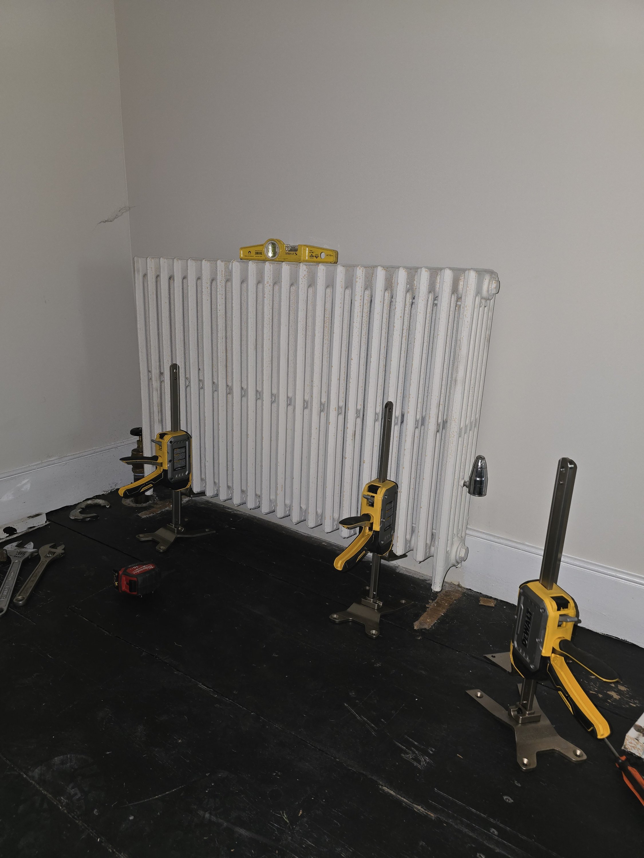
Some background on my system. It is an apparently uncommon 2-pipe system; each radiator has a separate runout from the main; each radiator has a separate return to the a common wet return near the floor of the basement; so, the returns do not communicate with each other; the radiators have generic supply valves (not indexable; no orifices); there are no traps at the radiator; there are vents at each radiator return, in the basement near the ceiling; all but two of the returns were updated with Hoffman 1A in the 1970s; the two remaining are as in the pics; there are no other vents or mechanical contraptions or special pipe arrangements, just the boiler.
The house was built in the 1910s; originally with a Pierce coal-fired boiler and radiators; a Kel-Mac vapor system is named in the blueprints. Circa 1924, the Pierce was replaced with a Bryant gas boiler. In 1997, it was replaced with a commodity Carrier (Dunkirk) gas boiler; existing near piping was unchanged.
System works well except for 2 of 20 radiators; one (furthest) rarely heats; the other (much closer to boiler), the supply pipe bangs a bit and radiator rarely heats. Neither have the old vent attached. Oddly, the two radiators with the old vent heat nicely.
I would also like to find more info on the Kel-Mac system. LAOSH only has a 1/2 page mention.
Thanks.
EDIT: Additional details
- The vent is "Breck" (Moses P. Breckenridge), may be his 1868 design (unconfirmed);
- Is thought to have a bi-metal component to actuate the valve.
- The bottom thread fits 3/8" NPT;
- The adjust screw in the "L" does screw into the inner hole (found original key for this);
- The "L" outlet thread fits 1/8" NPT (not confirmed if actually tapered hole);
- Heating the vent with a flame did not cause it to close (perhaps broken or rusted;
- Placed in acetic acid (5%) for 3 days; de-rusted very well;
- Re-tried heating test to cause valve to close; did not close;
- Still unable to disassemble;
 pacoit

Re: I'm getting solar panels. I'll let you know how it goes in this discussion thread.
ok gang— the permits all cleared (state, utility, and town) and the solar install crew is coming early tomorrow morning so expect some more posts with photos

Re: Unrecognized return vent
That's a "spring-packed" valve. ISTR the washer on the stem compresses the spring against the packing which is located underneath the spring. Replacement packing would look like a washer with a hole in it the size of the stem.
Also, the stem is non-rising and has no threads on it. It engages with the threaded portion at the left, which runs in threads inside the bonnet (or sometimes in the valve body) to open and close the valve. This puts less wear on the packing, and is one reason these valves last as long as they do.
Not sure what the S stands for though.
