Control needed

does anyone have a suggestion on an in expensive controller, brand doesn’t matter that can be powered with 24vac, accepts a 10 k sensor (supply air) that has two normally open contacts? Make on temperature rise. One contact is necessary, but two stages (two contacts) would be preferred. I need to temporarily get a 100% OA unit working until the OEM controller can be installed. It is an older unit and the controller while still available has a long lead time. Thanks to all
Comments
-
pretty much all electronic setpoint controls are multi voltage and available as multi stage
They come with a sensor, not sure if it can be switched
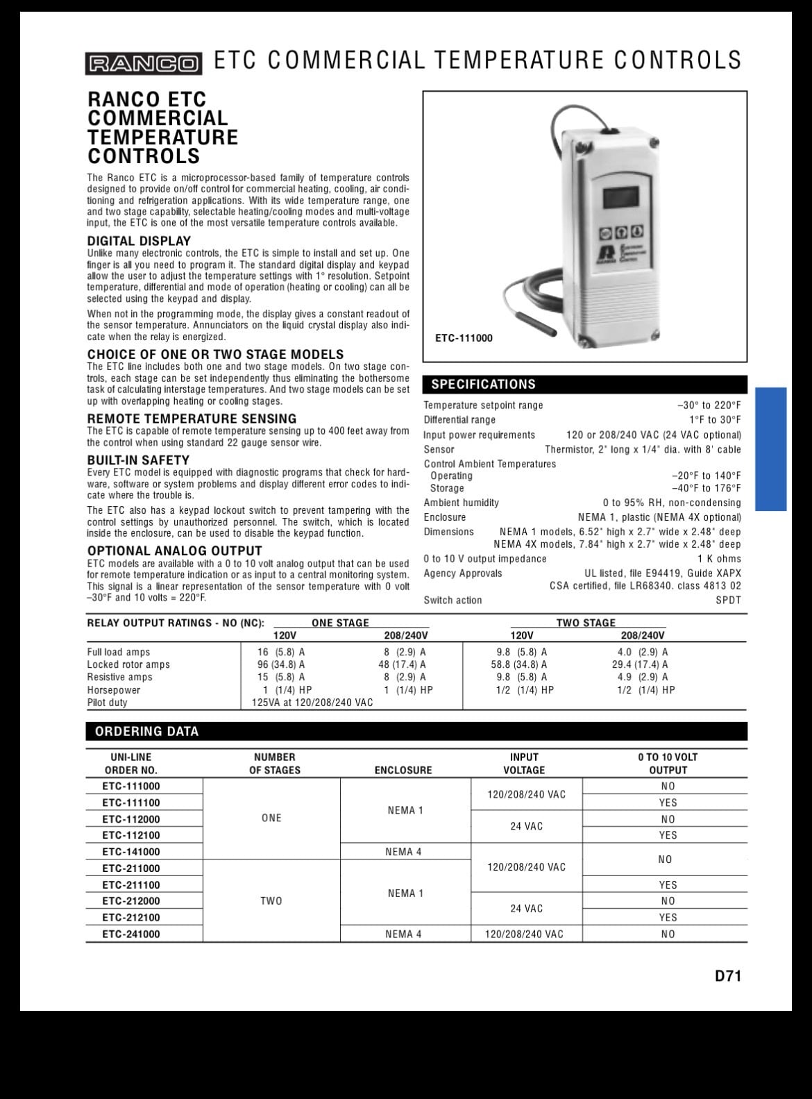
Ranco, Honeywell, Penn, Johnson Controls are some of the brands
Choosing heat or cool is what differentiates break on rise or fall
 Bob "hot rod" Rohr
trainer for Caleffi NA
Living the hydronic dream1 -
Omron may have something you like.
Many temperature controllers out there.
Many modern temperature controllers you can pick the temperature monitoring device from a menu like NTC Thermistor, Thermocouple (J, K, other), RTDs, etc.
National - U.S. Gas Boiler 45+ Years Old
Steam 300 SQ. FT. - EDR 347
One Pipe System0 -
Sadly the Ranco unit above does not specify the electrical characteristics of the sensor it uses.
" accepts a 10 k sensor (supply air) " Using an existing sensor may have unexpected results.
National - U.S. Gas Boiler 45+ Years Old
Steam 300 SQ. FT. - EDR 347
One Pipe System0 -
I think the TSS2-2400 checks all your boxes, you will have to program it .
TSS2-2400
Dual stage temperature switch, °F, 24 VAC/DC.Dwyer-Omega
LOVE CONTROLS DIVISION
www.love-controls.com
DWYER INSTRUMENTS INC.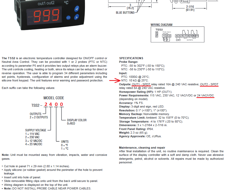 National - U.S. Gas Boiler 45+ Years Old
Steam 300 SQ. FT. - EDR 347
One Pipe System1 -
TSS2-2400 maybe configured like this. I believe P5 - Number of Probes needs to be set to 1.
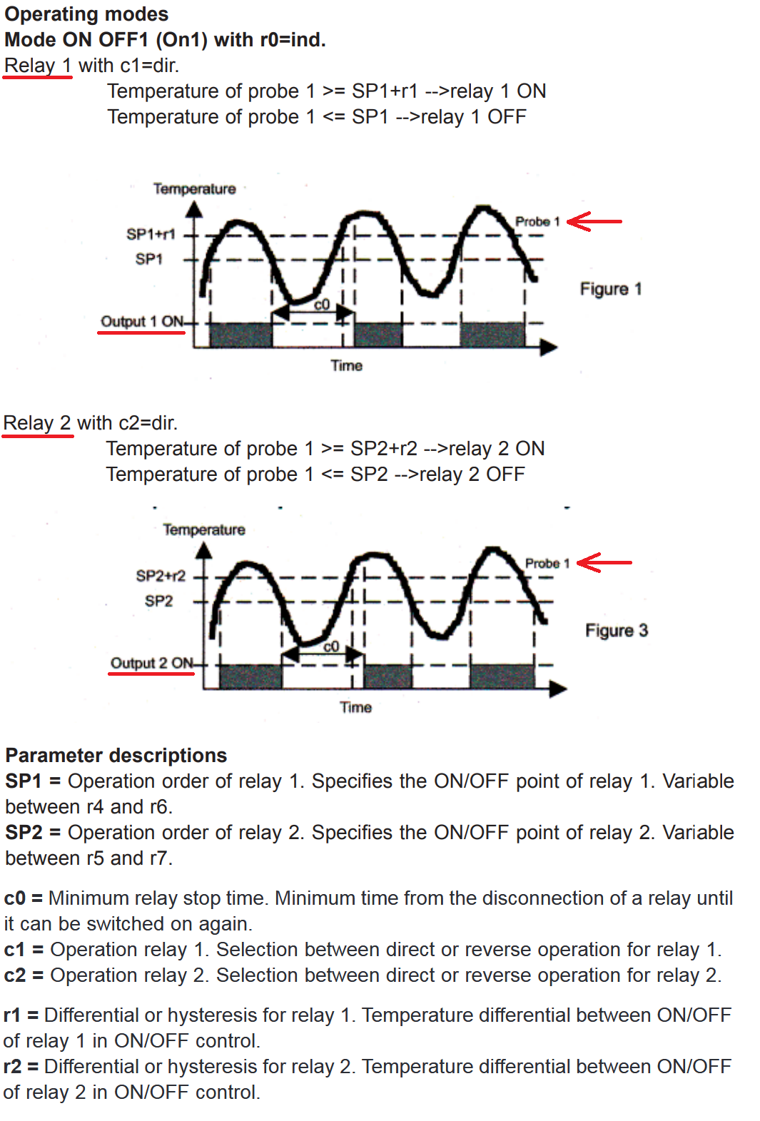
https://www.dwyeromega.com/en-us/dual-stage-temp-switch-with-dual-sensor-inputs-for-precise-control/Series-TSS2/p/TSS2-2400
National - U.S. Gas Boiler 45+ Years Old
Steam 300 SQ. FT. - EDR 347
One Pipe System0 -
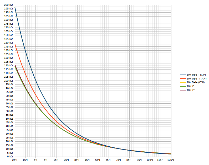
I've used the ETC/Ranco models in the past, simple and reliable. The sensor can be extended if necessary, just place it somewhere in the discharge air stream. If the two sensors are both 10K, even if they're different types you should be able to adjust the setpoint to account for it, They diverge pretty quickly temperature descending, but not temperature ascending:
 0
-
thanks to all that responded. Unfortunately all the controls mentioned were not available locally today. I ended up putting a two stage room thermostat in the and used the existing supply air sensor as the remote sensor for the thermostat. All that is needed for now is the unit to run and supply 70 degree air, the unit is 100% outside air
the bad part is the main board is no longer made by the manufacturer, AAON. You have to purchase a control upgrade package where basically ever board in the unit gets replaced, and a significant amount of rewiring needs to be done. The kit cost $8000.00 and the last unit I did like this it was a solid day and a half of work.
I was looking into getting the VCM board repaired. The DC power supply is gone, and some of the on board relays don’t work.
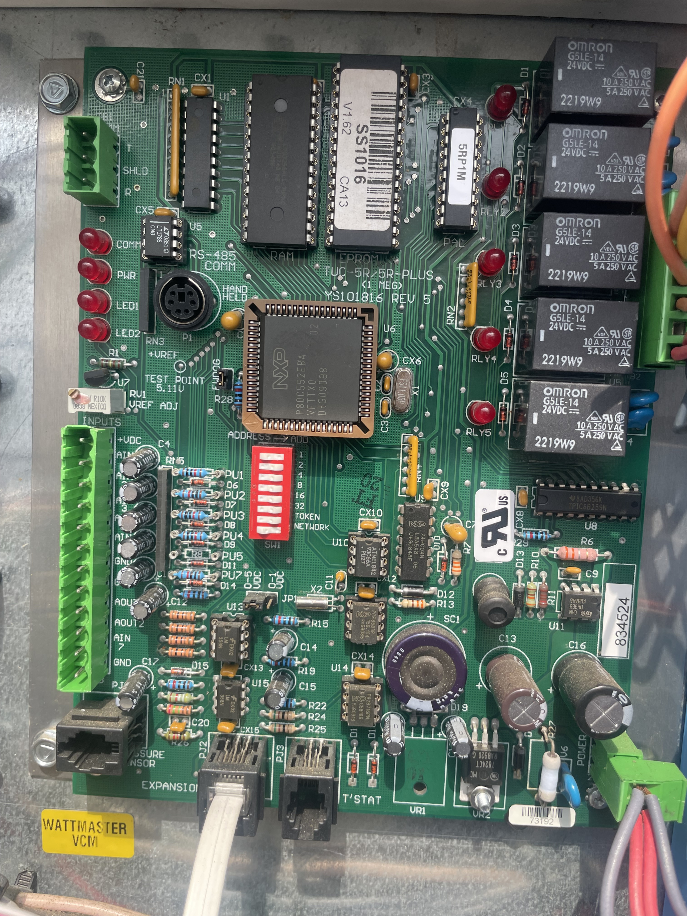
does anyone know of a company that can repair and test after repair the below pictured VCM board? Randell lists one a refurbished model, but there is no connection for the modular service toolThanks to all
 0
-
Well the DC power supply looks dirt simple. If the unit is totally dead (no +24 VDC) I wonder if R27 baked itself to death and it is now open. Another possibility is some facet of the circuit board or the system overloaded the power supply on the board causing R27 to bake itself to death and it is now open.
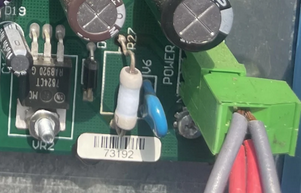
If the unit is non-functional how do you know if the relays are defective?
U11 and the surrounding components may make the +5 DC for the digital logic stuff. Looks like the circuit is right out of the datasheet.
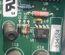
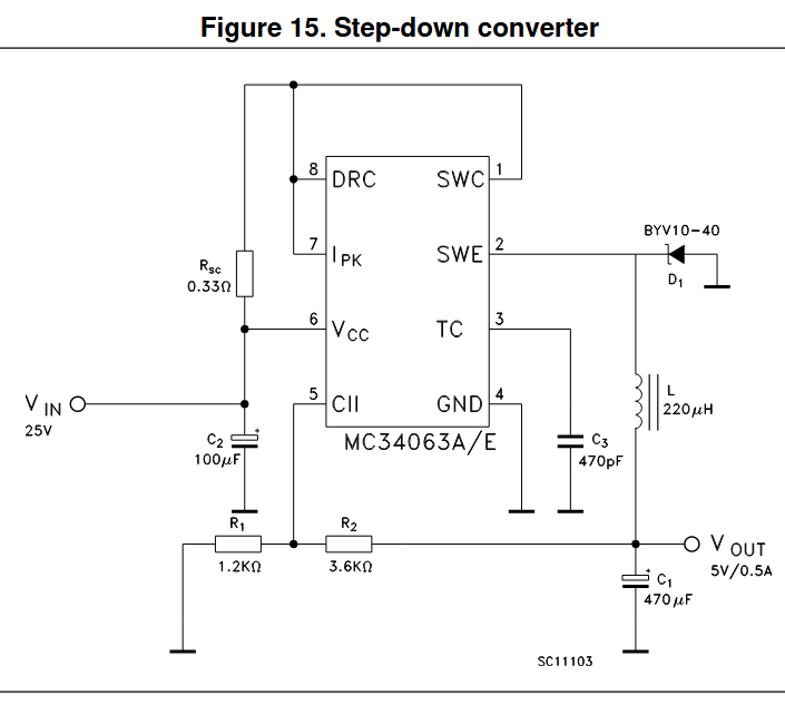
Looks like the relays are available. G5LE-14 24VDC
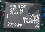 National - U.S. Gas Boiler 45+ Years Old
Steam 300 SQ. FT. - EDR 347
One Pipe System1 -
As I posted in your other thread;
There are places that can possibly repair it. Here are two examples;
http://hvac-circuit-board-repair.com
https://www.upfix.com
I have not used them, I do my own component level repair work. Often it
is just loose connections (connector pin fitment), crimped connections,
bad solder joints, failed relay contacts and/or bad capacitors.Edit: If you do an internet search you may find many other companies that basically advertise industrial electronics repair. You would have to find one in your price range with a reasonable turn around time you can deal with.
National - U.S. Gas Boiler 45+ Years Old
Steam 300 SQ. FT. - EDR 347
One Pipe System1 -
thanks to all the responded. The board has 24 vac going to it, but no 12vdc available for the analog outputs. Some of the relays stopped working first. They say with the modular service tool that they are energized, but the contacts are open and the indicator lights are off. It is either the relay contacts, or the logic not getting to the relay coil.
Some of the unit was able to function with the relay issue, but when the DC power supply went, the unit shut down.
We are almost forced to try and fix ourselves, because my concern sending it somewhere, that unless they have the modular service tool to confirm the board is working, I don’t see how they could confirm it’s repaired
thanks to all0 -
if it lost one of the power supplies that should be relatively easy to troubleshoot and fix without the tool that talks to the processor. one cant' 100% confirm that it is working but they can figure out if they fixed the power supply. it is also possible something shorted and is pulling down a power supply. i see a 24vdc linear regulator, a 7824 in the lower right hand corner but I don't see a rectifier for it. is this fed by a dc power supply somewhere rather than a 24vac control xfmr?
1 -
it is feed with 24 vac only. The board has an internal Dc power supply. The DC is for the analog outputs. The 24vac is for the relay outputs
0 -
Yes, repair confirmation depending on the situation can be tricky and ultimately done upon re-installation. A place that does a lot of HVAC board repairs may have the "modular service tool" and fixtures to confirm the repair. If they have been in business for years they collect tools like that.
As far as the relays, they are inexpensive and they may just change them all. It maybe an obvious failed solder joint(s). Looking at the board it looks like the LEDs are on the control (coil) side of the relays. It could be the latch chip (U8) used to control the relays, it could be the socket connections of the microcontroller (U6).
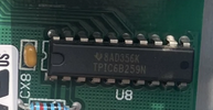
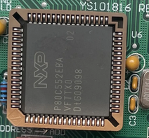
But like you stated without the DC power supply working the relay issue is irrelevant.
In this case I'd start with a visual inspection of the solder side of the board then apply power and see if the unregulated voltage and the regulated +24 VDC is at VR2.
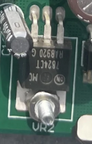 National - U.S. Gas Boiler 45+ Years Old
Steam 300 SQ. FT. - EDR 347
One Pipe System0 -
or more likely the supply that is missing isn't missing but is low or low current and it can drive a coupel relays but not all of them.
0 -
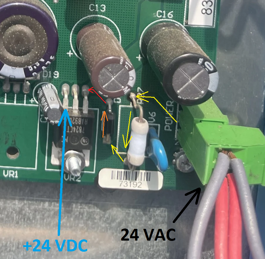
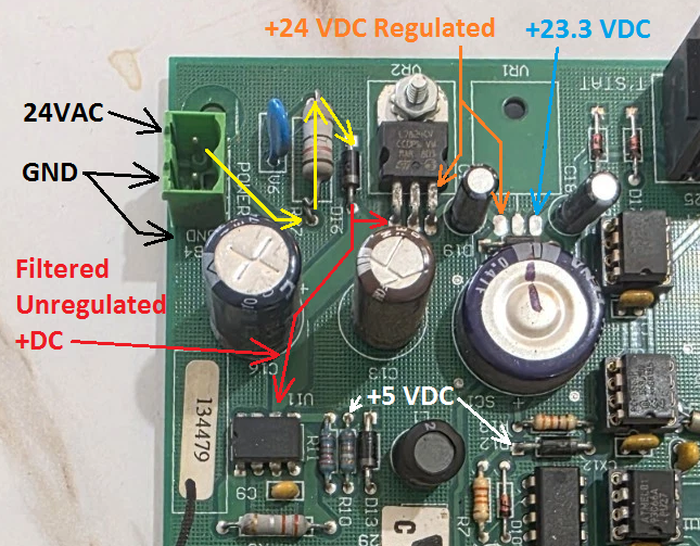
The Rectifier diode is next to the Orange arrow. Yellow AC path, Red unregulated DC probably at least 30 VDC, Blue regulated +24 VDC.
They probably went with half wave rectification so all the grounds or (common low side) are the same AC and DC.
 National - U.S. Gas Boiler 45+ Years Old
Steam 300 SQ. FT. - EDR 347
One Pipe System1 -
also somewhat likely it splits the 24vdc in to +- 12vdc for the com and it is possible it is missing the -12v
0 -
if one wanted to look at the datasheets for all of those ICs it would become obvious how it works.
0 -
I think that is less likely. @zepfan stated "The board has 24 vac going to it, but no 12vdc available for the analog outputs. Some of the relays stopped working first."
The LEDs look like they are on the control side of the relay, in your scenario dim LEDs would probably be noticed.
National - U.S. Gas Boiler 45+ Years Old
Steam 300 SQ. FT. - EDR 347
One Pipe System0 -
Fix the DC power supply first. Other than curiosity, the rest will not work without the power supply working. There is really not much there. DC power supply, microprocessor and memory, status LEDs, relay control, a TTL logic chip, network interface, a RTC, and an analog section.
National - U.S. Gas Boiler 45+ Years Old
Steam 300 SQ. FT. - EDR 347
One Pipe System0 -
multiple relays failing at once isn't very likely unless they are connected to something outside the circuit that could have fried them. the relays mechanically or electrically failing so they don't pull in is fairly unlikely, normally the contacts burn before any other failure although i have seen the armature break occasionally. I would also check the damper diodes on the relays to see if one of them is shorted. the microcontroller may have multiple ground paths and one of those might be missing although usually that type of socket and the soldering of said socket is pretty solid. It could have some components hanging off it that have failed.
0 -
Look at the way the relay control latch chip works. It is binary 1, 2, 4. It is very plausible if 1, 2 is missing multiple relays won't work.
And to me it is not known if they all failed at the same time, possibly just noticed at the same time.
National - U.S. Gas Boiler 45+ Years Old
Steam 300 SQ. FT. - EDR 347
One Pipe System0 -
is there a separate chip to drive the relays? i assumed they were just on io pins of the microcontroller but i didn't look up everything on that board. If the voltage is low but not missing altogether discreet logic is going to act weird.
0 -
I suspect everything and then follow the evidence. Guessing is fun, but not a good way to troubleshoot. Repair the power (in this case the DC power supply) and any other obvious defects first. Then move on with functional evidence based troubleshooting.
National - U.S. Gas Boiler 45+ Years Old
Steam 300 SQ. FT. - EDR 347
One Pipe System0 -
I did not lookup everything either, some I found were obvious, look at where the U8 traces go.
Look at U7 probably for the analog section +VREF (5.11 VDC), I can't see the chip number, probably a TL431.
National - U.S. Gas Boiler 45+ Years Old
Steam 300 SQ. FT. - EDR 347
One Pipe System 1
-
yeah, i assumed that u7 is an adjustable linear voltage regulator in a to92 case. I could see it making the 12v for the analog io too.
0 -
Yes.
U7 could also be a fixed 12 voltage regulator LM78L12 and +VREF is just a resistor voltage divider with a Pot. Is VR1 (maybe a 12 volt regulator) on the back side for heat sinking to the mounting plate? D19 has me wondering what is going on there.
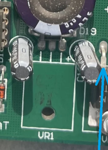
It appears the Analog In may go to the microcontroller the Analog Out is buffered by the Op-Amps
Much more would be very obvious if the board was in my hands.
National - U.S. Gas Boiler 45+ Years Old
Steam 300 SQ. FT. - EDR 347
One Pipe System1 -
Honeywell has a controller that will control the pre heats / reheats to control discharge air
0 -
vr1 is probably for an option that board does not have.
I didn't see d19 until now. that and the diode below c13 probably are a half wave rectifier for a low current 24vdc supply. If one of those is bad you would only have unregualted 12v on the 24vdc bus which some stuff would probably work on and other things woudln't.
0 -
thanks to all that responded, and in such great detail. Yes I have used the Honeywell T775 standalone controller in many applications to recontrol units, and boilers. They work great.
0 -
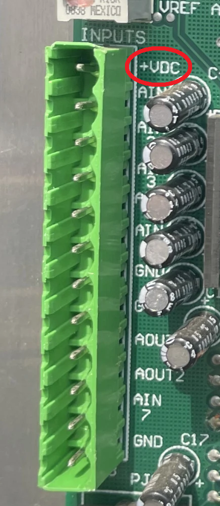
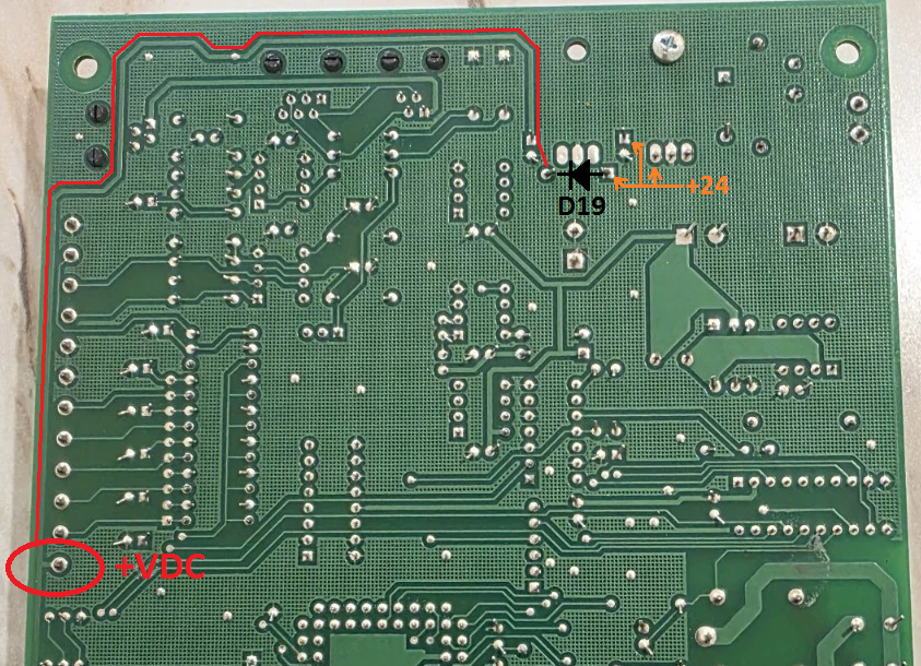
Looking at the back side of the board I'd say +VDC (Analog connector) should be about 23.3 VDC. LM7824 Regulator (24 VDC) minus the forward voltage drop of D19. I see no evidence of a +12 VDC rail.
If +VDC (Analog connector) was actually found at +12 VDC at some point, I say something was overloading the +VDC rail causing R27 to overheat and possibly fail.
If the +VDC was significantly low I suspect the +24 VDC would also be low. The relay coils are powered by the +24 VDC so maybe as @mattmia2 suggested that caused incorrect relay behavior. And dim LED indicators were just not noticed. The relay datasheet does not seen to have a specification for minimum pull in voltage.
 National - U.S. Gas Boiler 45+ Years Old
Steam 300 SQ. FT. - EDR 347
One Pipe System0 -
@zepfan " We are almost forced to try and fix ourselves "
If you are going to attempt a repair yourself here are the Voltages I would expect. All Voltages are referenced to Common or GND (screw on VR2). All you would need is 24 VAC at the power connector and a multimeter.
My bet is R27 is open, also I'm thinking R27 may be 1 Ohm at 1 Watt, I'd probably check it with an Ohmmeter first. Another thing (other than items previously mentioned) that could cause R27 failure is if V6 (the blue MOV next to R27) is excessively electrically leaky, causing an extra parasitic current through R27.
The Yellow arrows are the 24VAC path. The Filtered Unregulated +DC (Red arrows) will probably be in the 30 ish Volts (or higher) ballpark depending on the load. The +24, +23.3 (+VDC at the Analog connector) and 5 VDC should all be present.
 National - U.S. Gas Boiler 45+ Years Old
Steam 300 SQ. FT. - EDR 347
One Pipe System1 -
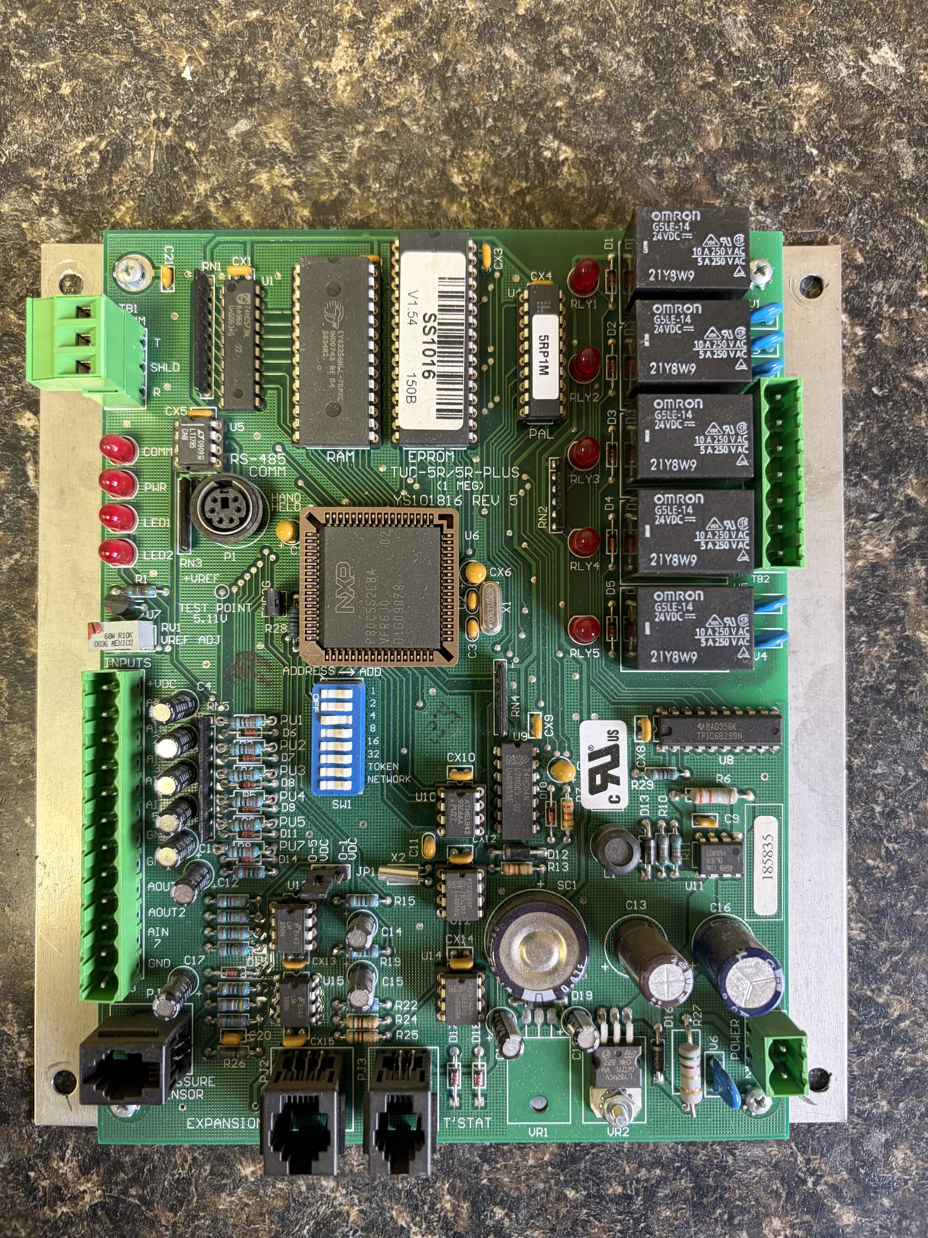
this is a working pull from an Aaon unit we reworked some years ago, looks like it might be an older versions, if you want it it’s yours.
1 -
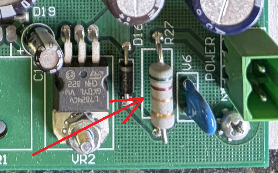
@Matt_67 Curious, on your board what colors are the color bands on resistor R27.
In your picture they look like Black Brown Gold Gold to me, in other pictures they look different, which may be from heat damage. Your R27 looks in good shape.
 National - U.S. Gas Boiler 45+ Years Old
Steam 300 SQ. FT. - EDR 347
One Pipe System0 -
Many of the chips are socketed, and good quality sockets too, nice !!!
Looks like @Matt_67's circuit board revision is the same as @zepfan's board (YS101816 REV 5). Assuming @zepfan's EPROM (V1.62) is still good, the EPROMs of both boards could be carefully removed and swapped. Updating the donor's earlier revision (V1.54).
carefully = low (no) static environment, don't damage the pins, make sure ALL the pins go where they should go, DON'T put the chip in backwards (spinning it 180 degrees).
National - U.S. Gas Boiler 45+ Years Old
Steam 300 SQ. FT. - EDR 347
One Pipe System1 -
thanks again to all that took their valuable time to respond to this. The board has 24vac going to it. I am reading 19vac across R27 with power applied to the board. With the power off I read a resistance of 6.0 M, that is with a fluke 116 set on resistance
D16 appears to be good as I am only reading resistance in one direction as relation to the negative meter lead on the cathode.
I am not reading any VDC on the two outer points of VR2, to the ground screw of VR2I am reading .3 ohms across v6
thanks again0 -
With the data provided, it sounds like V6 is shorted (0.3 Ohms), its resistance should read nearly infinity. Then with the short on the load side of R27 it overheated to the point it functionally became an open circuit, " I am reading 19vac across R27 with power applied to the board. " and " a resistance of 6.0 M ".
I would remove V6 and redo the Ohmmeter tests to verify V6 is defective if so then I would replace V6 and R27 and redo the powered up testing. BTW the circuit should work without V6 and R27 replaced, just that there will be no over-voltage spike protection.
The question is what is the correct value for R27 ? in @Matt_67 photo it looks like 0.1 Ohms 5 % 1 Watt, Black, Brown, Gold, Gold. In other pictures I found it looks like 1.0 Ohms, Black, Brown, Black, Gold.
When everything is working normally the value of R27 is probably not terribly critical as long as it is low enough for the rest of the circuit to function properly. If for example if V6 shorts (or becomes excessively leaky) R27 helps limit the current and will burn up internally acting like a fuse (which apparently it did). It also helps limit the current in the event of an over-voltage spike when V6 clamps the over-voltage spike event.
National - U.S. Gas Boiler 45+ Years Old
Steam 300 SQ. FT. - EDR 347
One Pipe System1 -
In this case since +12 VDC was mentioned and I see no provision for a +12 Volt rail, I wonder if the Analog +VDC was being significantly loaded down by some external device causing R27 to overheat. The overheating R27 may have lead to a premature death of V6. Even if this board is repaired or replaced there still maybe another issue that needs to be addressed for long term reliability. As mentioned before if the Analog +VDC was overloaded it would also load down the +24 VDC possibly causing odd relay behavior, since the +24 VDC powers the relays.
National - U.S. Gas Boiler 45+ Years Old
Steam 300 SQ. FT. - EDR 347
One Pipe System1


Categories
- All Categories
- 87.9K THE MAIN WALL
- 3.3K A-C, Heat Pumps & Refrigeration
- 60 Biomass
- 430 Carbon Monoxide Awareness
- 134 Chimneys & Flues
- 2.2K Domestic Hot Water
- 6K Gas Heating
- 124 Geothermal
- 170 Indoor-Air Quality
- 3.9K Oil Heating
- 80 Pipe Deterioration
- 1.1K Plumbing
- 6.7K Radiant Heating
- 397 Solar
- 16.1K Strictly Steam
- 3.5K Thermostats and Controls
- 56 Water Quality
- 51 Industry Classes
- 51 Job Opportunities
- 18 Recall Announcements