Taco needs to create an animation of how the 570 series zone valve works.
Comments
-
@Steamhead 's comment just above is why if I'm going to play with electrics I ALWAS use both a non-contact and a contact type tester to verify that the circuit really is dead. I don't like shocks…
Br. Jamie, osb
Building superintendent/caretaker, 7200 sq. ft. historic house museum with dependencies in New England0 -
@Steamhead "There was no polarity in the early days…."
Even back then, there was always a "hot" and always a "neutral", no?
And they usually fused the hot side.
 8.33 lbs./gal. x 60 min./hr. x 20°ΔT = 10,000 BTU's/hour
Two btu per sq ft for degree difference for a slab0 -
The thing is with @Steamhead's comment above and if you understand the 3 wire actuator circuit situation and you understand the 24 VAC in the heating equipment (the power for the T-T) may be bonded to ground in the heating equipment or Aquastat, etc., then the other 24 VAC power source for the thermostat and wax motor can NOT be bonded to ground, it needs to be 'Floating'. Or if it is bonded to ground it needs to be phased correctly and someone else can unknowingly easily screw that up.
An isolation relay or Multi Zone control boxes (Isolated X-X) does make whole ground bonding, either by mistake or intent irrelevant. Since it adds another layer of isolation to the overall circuit situation.
4 wire actuators by design provide the isolation.
National - U.S. Gas Boiler 45+ Years Old
Steam 300 SQ. FT. - EDR 347
One Pipe System0 -
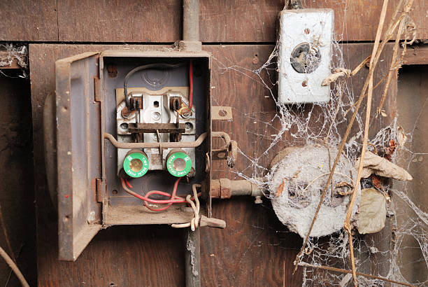
That thing looks scary.
I once knew an old-timer electrician (this was back in the 1970s and he was an old-timer then) who told me that. I had run into an old fuse panel where the neutrals were fused as well as the hots. Back when electric wiring was first being installed, in order to get 120v you might have 60v on either side, just like today's 120/240v service where 120v on opposite sides makes 240v. It all depended on how the local grid was set up. In those days, you only had to break one side of a circuit like that to control a light or other load. Obviously Codes have come a long way since then.
0 -
You know what is amusingly funny. The 3 wire actuator and two transformer secondaries is the same basic 120/240 circuit that powers most homes in the U.S. and Canada. It's just with the utility transformer the two secondaries contained and wired in a sealed can it is hard for others to mess it up. Each secondary has its own load and each secondary only 'Touches' the other at one point.
National - U.S. Gas Boiler 45+ Years Old
Steam 300 SQ. FT. - EDR 347
One Pipe System 1
1 -
Hay @JohnNY. You asked for this on June 5. How does this look.
It took a while to find some animation software on the web, but I found something that is not the best but got something that is usable. At least I think it is
I wonder what @SteveSan and others from Taco might think about it?
Edward Young Retired
After you make that expensive repair and you still have the same problem, What will you check next?



 8
8 -
I'd say that's pretty damn good, Mr. Ed. I'd click the "Awesome" button, but I think it's better than that.
8.33 lbs./gal. x 60 min./hr. x 20°ΔT = 10,000 BTU's/hour
Two btu per sq ft for degree difference for a slab1 -
That’s fantastic, @EdTheHeaterMan.
You did it! I’m beyond impressed and can’t thank you enough. What a great job.Contact John "JohnNY" Cataneo, NYC Master Plumber, Lic 1784
Consulting & Troubleshooting
Heating in NYC or NJ.
Classes1 -
Nice job on this, Ed.
With a disc jockeys voice also :)
Bob "hot rod" Rohr
trainer for Caleffi NA
Living the hydronic dream 2
2 -
That's really well done and captures the operation of the 570 series very well. Not much I can add other than a few quirky specifics. First off, the actual end switch is a normally closed switch and that little tab on the piston actually holds it open when the valve is closed. As the wax element pushed the piston down, the tab actually releases its hold on the end switch, allowing it to close the end switch circuit.
The description of the switch lifter on the other side of the piston is 100% accurate - and the fact that it opens and closes, causing the valve to oscillate, breaks the completed circuit on the power side. That does two things - it minimizes any worry of "cross talk," due to the fact the end switch and power circuits share terminal 2. Also, since it breaks power and makes the power draw intermittent, it's how we can put up to three of these babies on a 40 VA transformer, even though it the valve itself has an amp draw of 0.9A, or 21,6 VA. Since that draw is not continuous, you can easily put 3 on a 40VA transformer. The worst thing that will happen is that the valve action might slow down when two or three are all opening at the same time, which usually only happens on start up ur during testing.
0 -
@JBarba said: it's how we can put up to three of these babies on a 40 VA transformer, even though it the valve itself has an amp draw of 0.9A, or 21,6 VA. Since that draw is not continuous, you can easily put 3 on a 40VA transformer.
Thanks for that informatioin. I often wondered about the 0.9 Amp with 3 valves on one 40 VA tranaformer. That makes a little more sense now. I never lost sleep over it but I have wondered about it from time to time. Not like the things the really bother me like "Why is the word Abbrevation so long?" or "why we park on a driveway and drive on the Parkway. And a shipment sent by a car or truck but cargo is sent by ship?!? Those really keep me up at night.
Well I finally figured out how to actually render the video directly from the OpenToonz software app. This is a much better quality video
Edward Young Retired
After you make that expensive repair and you still have the same problem, What will you check next?
 1
1 -
To make things a little more interesting. I had a situation In a 30 unit building, Where I had to replace some 570s. But I had to use something where the direction of flow didn't matter. So, I used the Taco Sentry zone valves and Mario Silva from taco was good enough to send me the following diagram.
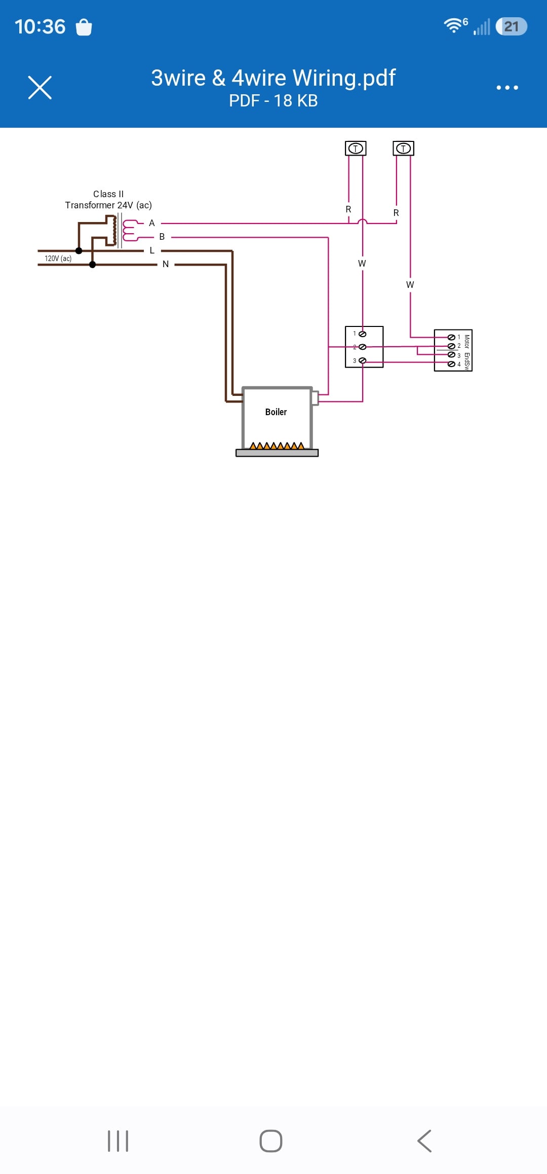 0
0 -
That would still blow the transformers if you got the wires crossed at the boiler. Isolation relays are not that expensive.
0 -
I like using RIB relays if only for the idiot light
1 -
@Steamhead said:
That would still blow the transformers if you got the wires crossed at the boiler. Isolation relays are not that expensive.And all I have to say about that is: the relay is unnecessary.
You can still cross the wires between zone valve terminals #2 and #3 that go to the relay and blow transformers.
You also add load to the transformer, so now you can no longer have three valves per 40 VA transformer. Adding the load of that relay to the zone valve transformer uses up more current and can end up overloading the transformers. Here is an example of how it works without isolation relays:

This is how I might see your Isolation relay design:

This works just as well with the additional relays. However in the next diagram you will see the common mistake where the zones are connected identically and wvwn with the isolation relays there is still a short circuit when zone thermostat all the way to the left is calling for heat.
This is how @Steamhead might reconnect a thermostat on a repair to a system I installed . That is because Steamhead is correct in his diagram, where R on the transformer is connected directly to #1 on the zone valve the way he was taught many, many …many years ago.
If all the other valves were connected the same way, with R connected directly to #1 on each zone valve, then there would be no problem.
The problem arises when @Steamhead comes across a system wired the way I teach it, where R on the transformer is connected to R on the thermostat, and he does not double-check to see how all the other valves and thermostats are wired.
Then @Steamhead ’s correct way of doing this somehow causes the transformer to fail, even with isolation relays in place, as shown below.
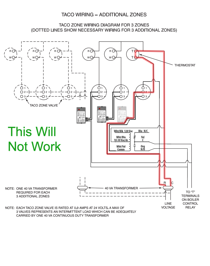
I’m not saying that @Steamhead is wrong . I’m saying that when troubleshooting three-wire zone valves, the way you were taught is not necessarily the same way everyone else was taught.
There is more than one correct way to wire zone valves. You just need consistency across the entire system that you are working on.
Edward Young Retired
After you make that expensive repair and you still have the same problem, What will you check next?
0 -
Well, that diagram won't work, but that's not what I meant.
As long as there is only one transformer feeding a group of ZVs, the outputs from terminal 3 on all of them can be grouped together and routed to the same isolation relay. The problem comes, again, where you cross-connect different transformers. Each group of ZVs that share a common transformer would need their own isolation relay. The NO contacts on each relay would then connect in parallel to TT on the boiler, so any one of the isolation relays can start the boiler. This is essentially what a zone valve panel does.
The idea, again, is to make the installation foolproof. You never know who's coming in after you, and you don't want them blowing transformers and controls. Customers don't appreciate that.
0 -
Same difference, @Steamhead , whether you have one relay for each valve or one relay for all of the valves. The wires must be consistent across the system.
I like to use R on the transformer to R on the thermostat. You like R on the transformer to #1 on the zone valve. Both work fine when they are consistant
If you mix both of our methods on the same system, you will have smoked transformers, regardless of the relay.
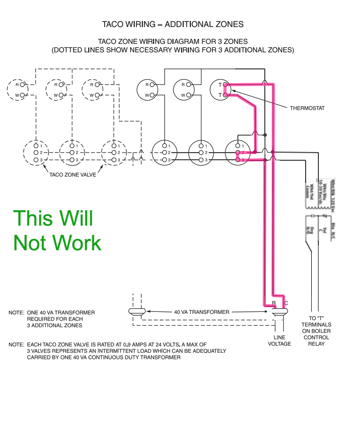
All the relay does is move the problem. It makes sure the inconsistency does not damage the control’s transformer, but the wiring inconsistency is still there.
The best way to solve this problem would have been for Taco to determine, 50+ years ago, that the transformer R, or non-grounded source, gets connected to R on the thermostat in their diagram.
But that will never happen, because it would make too many existing systems obsolete. It would, however, make adding smart thermostats that need a common, or C wire, much easier to retrofit.
Anyone who comes across a system wired where R from the transformer is connected directly to the zone valve needs to have the system completely rewired so every zone valve is connected the same way: R on the transformer to R on the thermostat, W on the thermostat to #1 on the zone valve, and the #2 terminal, common both circuits in the valve head, on the zone valve connected to C on the transformer.
It all fits together perfectly when it is done that way.
But if you have a six-zone-valve system, that is an expensive rewire just to add one Nest or ecobee thermostat to your home.
Edward Young Retired
After you make that expensive repair and you still have the same problem, What will you check next?
0 -
one condition that is possible, power is out for a period of time during a cold snap.
When power is restored all actuators are pulling max power and overload the transformer
The colder those wax actuators are, the longer the opening time.
Bob "hot rod" Rohr
trainer for Caleffi NA
Living the hydronic dream0 -
I like the relays for a couple of reasons.
If you go on a no heat call and walk up the boiler and the idiot light on the relay(s) is lit and the boiler is cold or not running, you have a boiler problem.
If the relay is not lit you have a zone valve thermostat or transformer issue or wiring issue.
It also eliminates an issue with two transformers tied to the same circuit (even though there is no issue it is less complicated)
I like those zone valves because the actuators are easy to change and that series of valves usually has a higher Cv rating than other valves of the same pipe size.
I do prefer an isolated end switch, however.
So IMHO easier to troubleshoot with relays.
0 -
Then get the ZVC relay, not the RIB as suggested …because the ZVC has more lights so you know more and makes the wiring much less complicated. With RIB to isolate you still can have the problems that not using a relay at all can have. Do it right, not cheap!
The RIB does not change how the zone valve operates.
I think I might create a video animation of this comment:
it's about how there are several ways to connect wires to a Taco 3 wire Valve that work, but don't mix and match on the same system:
Edward Young Retired
After you make that expensive repair and you still have the same problem, What will you check next?
 3
3 -
Well the way I see it, all @EdTheHeaterMan, @Steamhead, @EBEBRATT-Ed, @hot_rod all have valid points.
IMO you don't need a relay to make the circuit work properly. Any more than you need a relay to add a new TV to your home. The circuit comparison is more similar than you may think.
What I don't like about adding things that are not actually needed for proper operation is it complicates the wiring and increases the cost, initially and to run, and more stuff to fail. Making it more complicated is just making it more complicated for the next guy. If you left a perfectly good working (neatly wired) circuit and the next guy screws it up, well that is on them, not you. Also LED indicators like the RIB has can and do fail, trust your meter that you verified before each use and not the indicators.
To me if you are going to go with the added relay circuit topology, use a zone valve controller, since it simplifies the wiring, provides isolation and activity indication, but it has a cost.
The one thing I find sad about the original @JohnNY post is this circuit is not that complicated. I hope that electrician never has to troubleshoot Polyphase equipment issues.
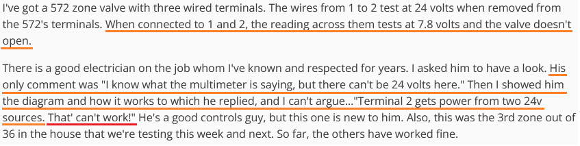
Was this inoperative zone valve issue ever resolved ??? If so, what was found ?
National - U.S. Gas Boiler 45+ Years Old
Steam 300 SQ. FT. - EDR 347
One Pipe System1 -
@109A_5 posted" Was this inoperative zone valve issue ever resolved ??? If so, what was found ?
And I'm interested in finding out how the issue was resolved also
Hay @JohnNY, what's the scoop?
Edward Young Retired
After you make that expensive repair and you still have the same problem, What will you check next?
1 -
You can wire anyway you want that works. I have wired them with relays and without.
What I am saying is that by using relays it more closely follows the wiring of a 4 wire valve where the valve power and its opening and closing is controlled by 1 circuit and the burner control is isolated by an end switch or in the case of these Taco valves by a relay.
I am simply trying to "dumb it down" as the average "technician" on the street is not going to have a clue what to do with these valves especially with multiple valves on one boiler.
Strangely if I remember right Taco does not describe the operation of the valve or its (two transformer) integration in the install instructions.
It is in the sales brochure which most technicians are not going to know to access that while on a service call.
0 -
Wait util that "average technician" comes across a WR 1361 with 5 wire connections.
Bob "hot rod" Rohr
trainer for Caleffi NA
Living the hydronic dream0 -
Not a big fan of ;

The average technician should learn their trade, the information is not hard to find if you look.
Be above average.
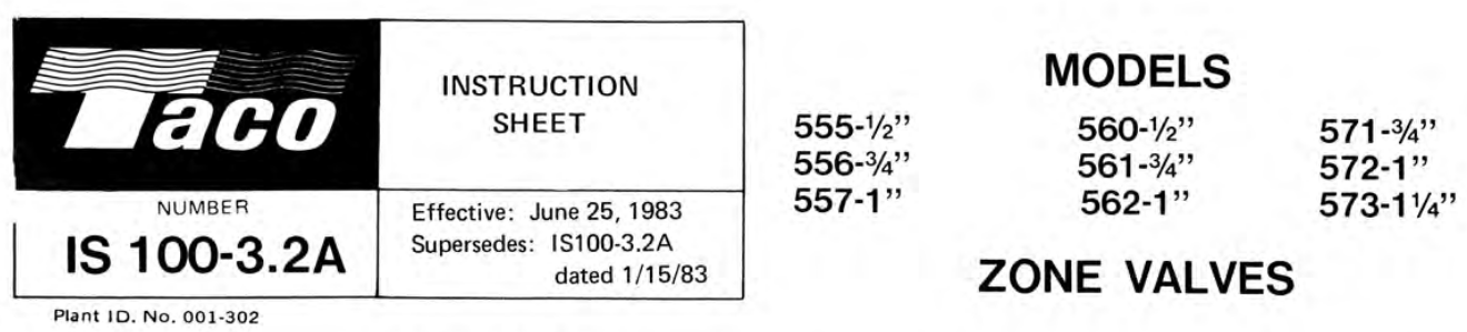
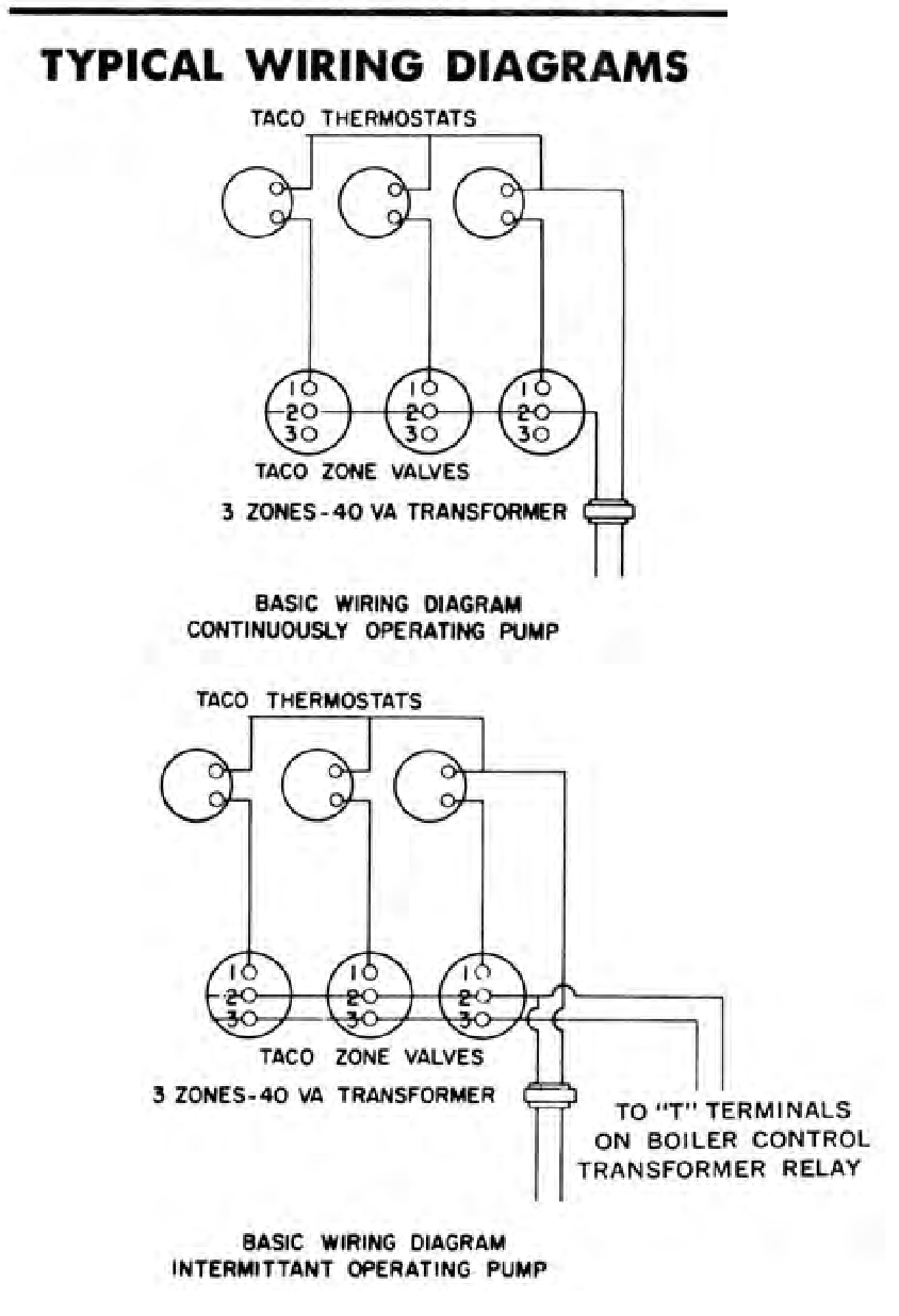
This install instruction shows this wiring diagram only. As previously stated the theory of operation is not in this document. But it is out there and most any technician has a phone that it could be found with. Technicians should be able to do research as needed.
 National - U.S. Gas Boiler 45+ Years Old
Steam 300 SQ. FT. - EDR 347
One Pipe System 2
2 -
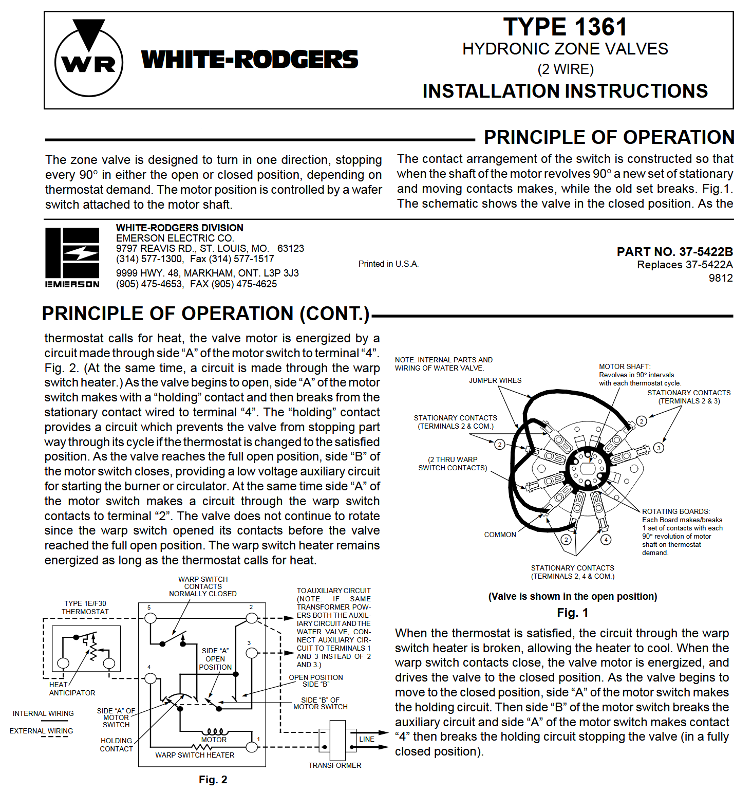
The install manual for the WR 1361 has the theory of operation and install wiring examples. Interestingly even with the extra terminals it is ultimately very similar to the Taco 570 series, no isolated End Switch.
 National - U.S. Gas Boiler 45+ Years Old
Steam 300 SQ. FT. - EDR 347
One Pipe System0 -
I don’t know of many, any, hydronic components that don’t come with installation manuals. Especially controls.
Or many techs that don’t have phones or tablets with them?
Many manufacturers gave short online videos for non readers
Shop have internal training sessions presented by reps and manufacturers.
If the technician goes into the field without training or access to a senior at the company, a txt of phone call away… whos fault is that?
Especially in the case if a 570 valve, been around what 50 years!Bob "hot rod" Rohr
trainer for Caleffi NA
Living the hydronic dream0 -
So everything thinks I am wrong dumming it down with relays. The Taco instructions do not talk about intermingling two transformers (only shown in the brochure) and I would be willing to bet $100 that most technicians saw two transformers connected on the secondary like that they would think it was wrong.
Everyone has this vision of well-trained techs. Get real. Most of the stories and pictures we see on this site are real and the problems stare us all in the face and they are a lot simpler that a low voltage transformer issue with two transformers
They are installing steam boilers every day and will not read the manual or get training what makes zone valves different?
0 -
@EBEBRATT-Ed, maybe the average Tech should wire it exactly as shown in the installation manual, no need to read the theory of operation. Then they can be amazed it works. Then in their amazement maybe they will do the research as to understand why it actually works. Or they can just not care and move on to the next task.
And if the average Tech is that inept why would they think of adding a relay in the first place ?
Oh my the windings are connected together. It can't work, but it does. How does it work ?
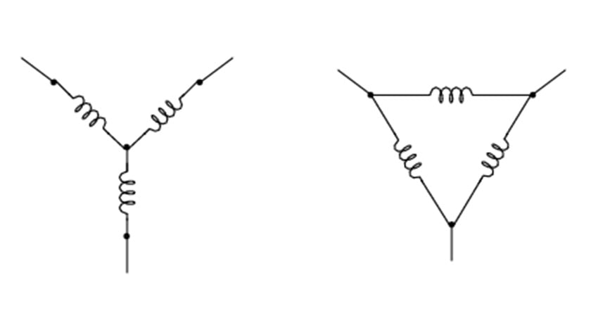
I realize a 3 phase example is a bit beyond the scope of wiring zone valves and thermostats. It is an easy example of secondaries connected together.
Another common example is the center tapped secondary or actually the two secondary windings of the common 120/240 electric utility transformer that powers most homes in North America. Homes are not littered with relays for every device plugged into a receptacle. There is more mechanical structure to wiring a house, but the electrical part is basically the same.
Besides even with adding relays you still can get smoke.
National - U.S. Gas Boiler 45+ Years Old
Steam 300 SQ. FT. - EDR 347
One Pipe System0



Categories
- All Categories
- 87.8K THE MAIN WALL
- 3.3K A-C, Heat Pumps & Refrigeration
- 60 Biomass
- 430 Carbon Monoxide Awareness
- 133 Chimneys & Flues
- 2.2K Domestic Hot Water
- 6K Gas Heating
- 124 Geothermal
- 170 Indoor-Air Quality
- 3.9K Oil Heating
- 79 Pipe Deterioration
- 1.1K Plumbing
- 6.7K Radiant Heating
- 397 Solar
- 16.1K Strictly Steam
- 3.5K Thermostats and Controls
- 56 Water Quality
- 51 Industry Classes
- 51 Job Opportunities
- 18 Recall Announcements