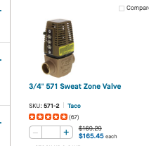
Taco needs to create an animation of how the 570 series zone valve works.

I've got a 572 zone valve with three wired terminals. The wires from 1 to 2 test at 24 volts when removed from the 572's terminals. When connected to 1 and 2, the reading across them tests at 7.8 volts and the valve doesn't open.
There is a good electrician on the job whom I've known and respected for years. I asked him to have a look. His only comment was "I know what the multimeter is saying, but there can't be 24 volts here." Then I showed him the diagram and how it works to which he replied, and I can't argue…"Terminal 2 gets power from two 24v sources. That' can't work!" He's a good controls guy, but this one is new to him. Also, this was the 3rd zone out of 36 in the house that we're testing this week and next. So far, the others have worked fine.
But we know, of course, that it does.
I've had this ancient, remarkably reliable device explained to me about 100 times in my career and I still don't get it. I implore John Barba, Dave Holdorf, or someone over there to create and release an animated explanation of the 570 series of zone valves.
Consulting & Troubleshooting
Heating in NYC or NJ.
Classes


Comments
-
They are a bit confusing at first — I certainly was anyway! But the secret is that the three terminals are really two completely different circuits. One (1 and 2) powers the zone valve to open when it gets power — from somewhere. The other 2 and 3 — is a simple limit switch which closes when the valve is open. Apply power to 1 and 2, and the valve motor is energized and the valve opens. When it is opened, the limit switch closes between 2 and 3 and you can use that closure for whatever.
Now there is a ringer in the deck: terminal 2 is common to two circuits. Whatever is sending the signal to open the valve is one circuit. Whatever the valve is telling to operate is the other.
Those circuits must be independent. In theory, under certain miswiring conditions, it is possible to set them up so that they can short out, but if both the independent 24 VAC circuits are intact and NOT GROUNDED this won't happen.
Br. Jamie, osb
Building superintendent/caretaker, 7200 sq. ft. historic house museum with dependencies in New England 2
2 -
@Jamie Hall But, looking at the diagram, it is absolutely true that the #2 terminal is receiving power from two 24v sources. Seems like trouble to me. And I don't understand the movement of the "heater switch." It ha also been said that the Heat Motor receives intermittent power and it relies of the slow workings of the valve to make or break the 2-3 closure.
I have to see it work or my head will surely explode.
Contact John "JohnNY" Cataneo, NYC Master Plumber, Lic 1784
Consulting & Troubleshooting
Heating in NYC or NJ.
Classes 2
2 -
Basically it works like this:
Terminal 2 receives 24v from R on the transformer. It is connected to the heat motor and the end switch.
Terminal 1comes from the other side of the heat motor and goes to the thermostat. When the thermostat switch closes, it connects to C on the transformer, and activates the heat motor to open the valve. The heater switch keeps the heat motor from overheating.
Terminal 3 comes from the end switch. When the valve opens, the end switch closes, outputting 24V to terminal 3. This tells the boiler to start. But the connection between the 570 and the boiler control can be problematic.
The danger comes from connecting two transformers together via terminal 3. This can burn the transformers up if they are not connected properly. I always use an isolation relay between the 570 and the boiler control, to prevent this. I've used a single relay to handle the Terminal 3 outputs from several 570s that are fed from the same transformer. Yes, it's an extra item and costs a few bucks, but it can save a lot of aggravation.
Baltimore, MD, USA
Steam, Vapor & Hot-Water Heating Specialists
Oil & Gas Burner Service
Consulting
 5
5 -
@Steamhead 's solution is the better one — isolation relays. There is no problem if the two completely separate 24 VAC circuits are, in fact, completely separate except at the #2 terminal of the valve (or valves — but I'll not get into that!). Where trouble can arise is if there are two connections possible between them, or where someone tries to use the boiler transformer to power a thermostat or something of that sort. Then you can fry transformers instantly. But not if it's wired correctly.
The isolation relay trick will work nicely in any case, and prevents errors from becoming problems!
One other gotcah I just thought of — the thermostat circuit has to be powered with a 24 VAC transformer with enough power to operate the valve motor. You can't just hook up two wires to the valve and two to the thermostat and expect anything to happen.
Br. Jamie, osb
Building superintendent/caretaker, 7200 sq. ft. historic house museum with dependencies in New England0 -
This is where the confusion starts: "Terminal 2 receives 24V from R on the transformer."
Don't think of it that way. That's how transformers get the factory-installed smoke to leave them.
Think of Terminal 2 as a common, or C terminal. When you look at it that way, it always makes sense. The problem is that not everyone thinks that way, and that's where the trouble begins.
When you come across a Taco 570 Series three-wire motor, where the transformer's 24V R is connected to #2 or common (C), things can get confusing. Eventually, when diagnosing a problem involving a transformer with R connected to the #2 or C terminal on a zone valve motor, you can end up connecting an R and a C from a transformer together.
We all know what happens when you connect R and C together on a transformer and then apply 120V to the primary winding. the factory installed smoke is released.
So think of the taco 570 series motor like this. R from the transformer goes to R on the thermostat. That makes sense all the time weather toy are wiring a heater or air conditioner or heat pump. R is always connected to R and if you use a Red insulated wire that makes it even easier to remember.
Now that you have connected one of the transformer wires to R on the thermostat, you need to connect W (the heat terminal on the thermostat) to something. That should be terminal #1 on the Taco 570 motor. This means that whenever there is a call for heat, the thermostat will send 24 VAC to the Taco motor.
However, that does not make a complete circuit for the Taco motor. You need a return path for the circuit to be complete. This is where terminal #2 becomes a Common (C) terminal. All you need to do is connect terminal #2 on the motor to C on the transformer. This completes the circuit.
That is really all you need to know about the Taco 570 series valve motor. There is more to learn, but if you want the basics to get it right every time, remember this:
Transformer R → Thermostat R (use the Red insulated wire)
Thermostat W → Taco 570 Motor Terminal #1 (use the White insulated wire)
Taco 570 Motor Terminal #2 → Transformer C (I like Blue for this, but use what ever color you have left in the bundle if spaghetti because electric is colorblind)Once you have this circuit in place, you can then use terminal #2 (Common) and terminal #3 on the Taco 570 motor as an end switch, independent of the thermostat circuit.
Edward Young Retired
After you make that expensive repair and you still have the same problem, What will you check next?
 2
2 -
Well, @EdTheHeaterMan , that's basically the mirror image of what I posted. I've seen it done both ways in the field. You can fry your transformers either way. This is why I always use isolation relays.
@Jamie Hall , in general a 40VA transformer can power three 570s.
Baltimore, MD, USA
Steam, Vapor & Hot-Water Heating Specialists
Oil & Gas Burner Service
Consulting1 -
Please forgive my ignorance, but I'm not seeing how you can hook the two transformers up the wrong way. Their phasing doesn't matter because they are actually two independent circuits, no?
Them being tied together on T2 doesn't really mean much.
What did I miss?
Single pipe 392sqft system with an EG-40 rated for 325sqft and it's silent and balanced at all times.
0 -
having been in tech support at Taco 25 years ago, this was one of the most asked question.
After reading this tread, there’s been several explanations of why #2 common terminal works. As long as the valve 2, & 3 terminal interface with TT terminals, dry contacts, there’s no issue.
If you continue to have questions contact Taco tech support at 401-942-8000 for further assistance.
Joe Mattiello
N. E. Regional Manger, Commercial Products
Taco Comfort Solutions4 -
Nothing. If it's wired as shown, there's no problem at all. In fact, it's a really very ingeniouos and quite reliable circucit.
Now if someone gets really clever and decides to ground one side of each transformer, you have a fifty/fifty chance of their being out of phase and, if the thermostat switch closes you can let all the factory smoke out…
Br. Jamie, osb
Building superintendent/caretaker, 7200 sq. ft. historic house museum with dependencies in New England1 -
many systems have one end of the secondary of the xfmr tied to ground. if both xfmrs have one end tied to ground then there is another wire connecting the 2 ckts together besides the 2 terminal on the zone valve so you could get anything from a valve or boiler that doesn't shut off to burned out transformers if you don't account for that extra wire when drawing your current paths.
0 -
I spoke to Wales Darby today. What I had trouble wrapping my head around with this actuator is… what really makes it work is that it takes so long to open and close. Terminals 2-3 stay closed while the heat motor pulses voltage to keep the stem in the open position.
It's absolutely an ingenious design, especially for its time I suppose, but testing them depends heavily on understanding the mechanics of their movement. At least for me. Because I'm a plumber? Maybe. Or maybe it's because I spent a lot of time listening to Led Zeppelin on 11 with headphones on as kid.Contact John "JohnNY" Cataneo, NYC Master Plumber, Lic 1784
Consulting & Troubleshooting
Heating in NYC or NJ.
Classes 4
4 -
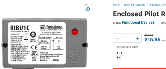
But T-T on a boiler are not dry contacts. They are energized in the burner circuit. Of course, Steamhead's addition of a relay, RIBU1C/S I'd imagine, would provide dry contacts. So, I guess that's the best way to install the 570 series. Thanks for weighing in, Joe, and everyone else.
Contact John "JohnNY" Cataneo, NYC Master Plumber, Lic 1784
Consulting & Troubleshooting
Heating in NYC or NJ.
Classes0 -
if i have a chance i'll draw the schematic with the 2 current paths, that is why it can work with 2 xfmrs. you can think of the heater in the heat motor side as a resistor or coil or light bulb for electrical flow purposes, that diagram of what is going on inside just makes it more confusing. unless you're doing something like calculating average power used or trying to troubleshoot one that is sticking you don't need to know about that, just that you give it power on 1-2 and eventually 2 connects to 3 when the valve opens.
0 -
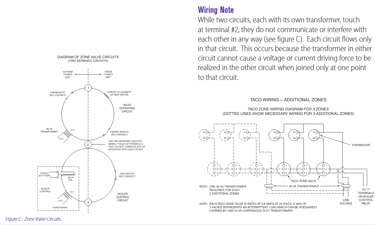
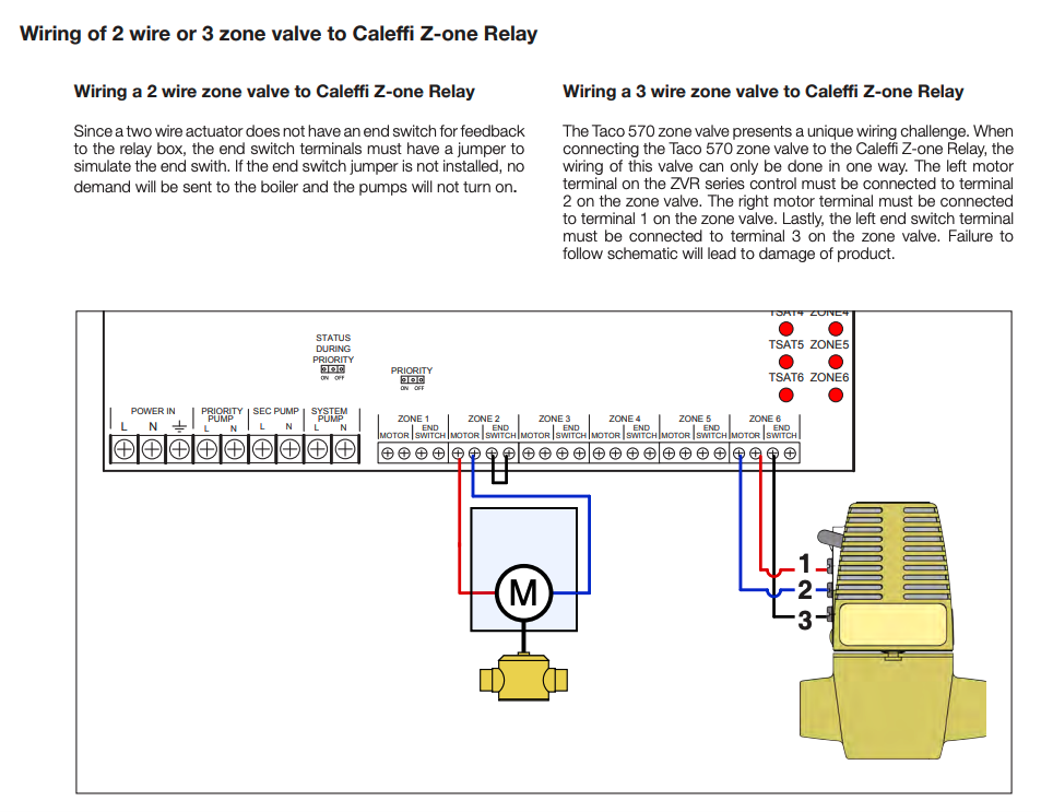
The answer in on the 3d page of this Taco brochure.
I used to struggle with this myself.
it's just cleaner and simpler to have a 4 wire valve with 2 valve wires and 2 end switch wire
The brochure explains
it perfectly
 1
1 -
my thought is if you're going to buy a relay you might as well just buy a 4 wire valve in the first place.
i suppose your options are buy a 4 wire zone valve or wire the 3 wire valve as intended and make sure you buy xfmrs with circuit breakers or replaceable fuses for when someone tries to replace one or add a t-stat that needs a c wire.
0 -
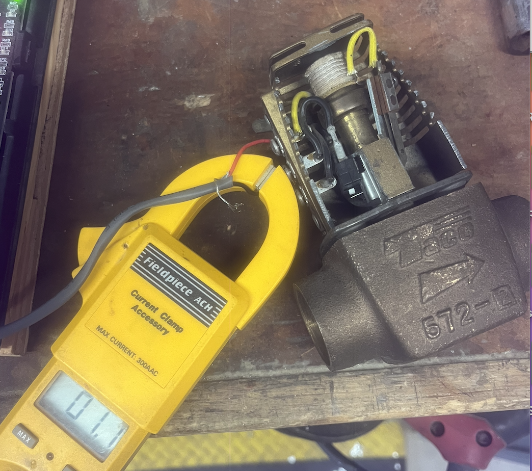
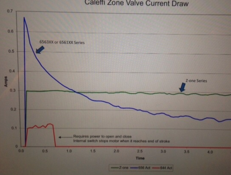
It operates differently than other thermal actuators or zone valves. I believe the stroke switch opens to drop power to the wax motor or it would over-stroke. Possibly the wax or oil inside over-heats? It pulses power about every 17 seconds.
When powered it pulls .9- 1.1a . Va= volts X amps .9a X 24V = 21.6. So 3 on a 24 transformer is a bit over.
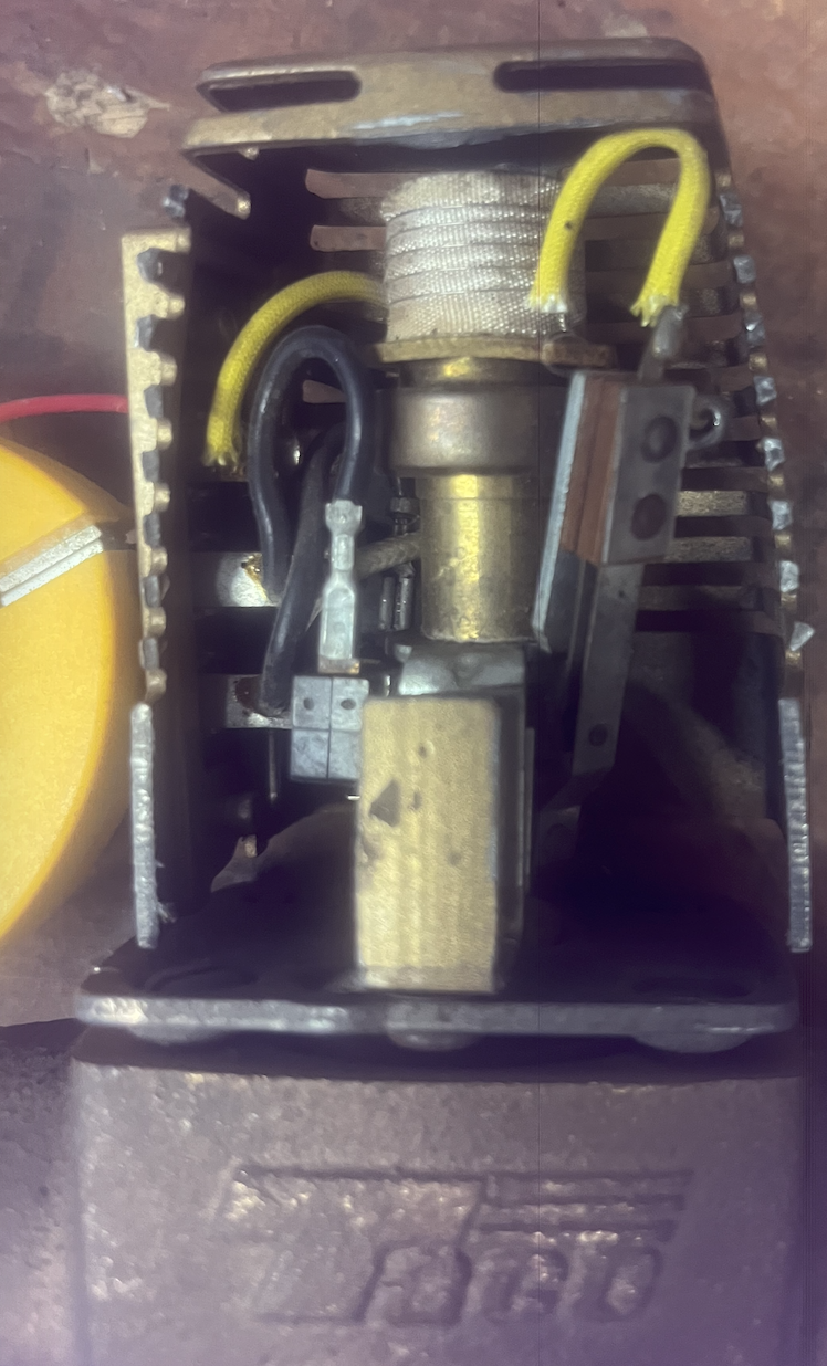
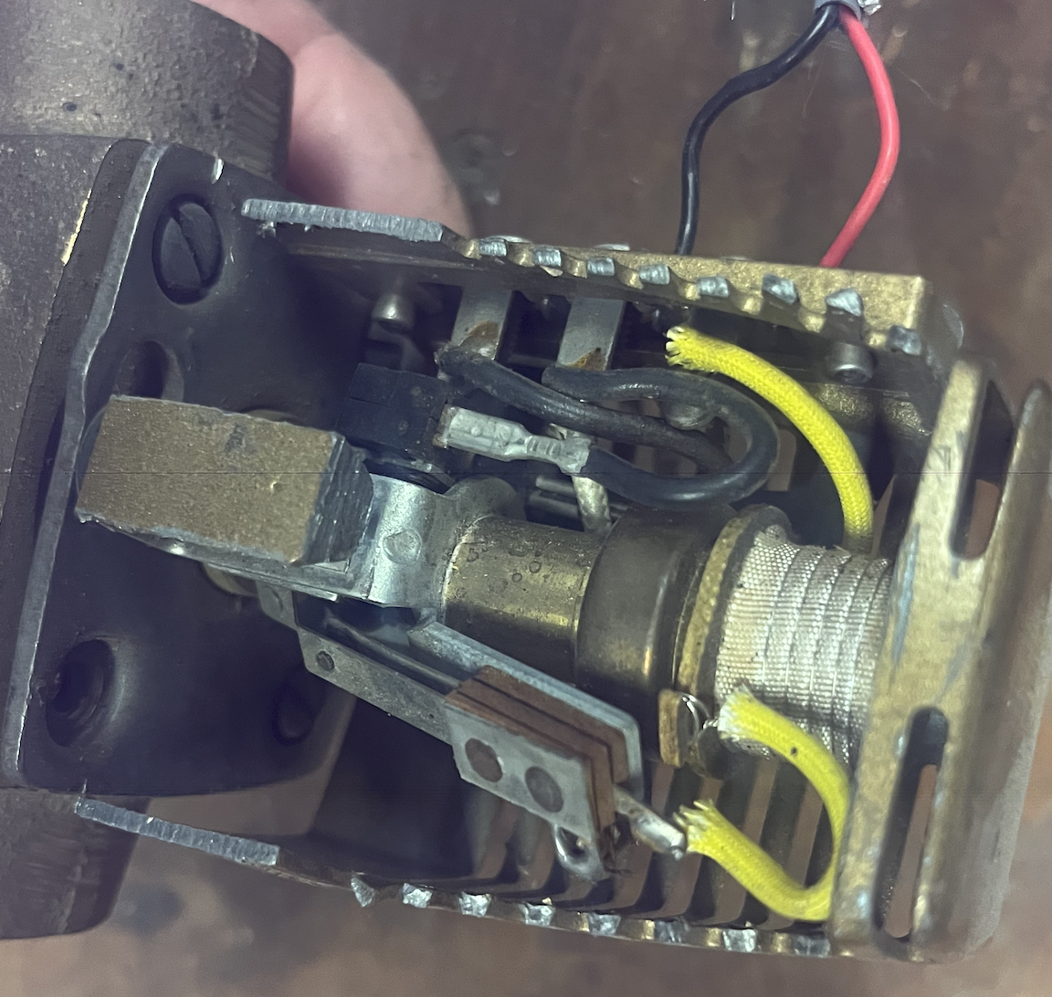
If you cut open the side of one you see where the terminals wire to, and it makes more sense.
Also watch the stroke and end switch working. A clamp on amp meter shows how the power constantly cycles to the wax motor. Yellow wires to heat motor, black to end switch.
The 250Ma thermal actuator, helmet heads, ZVs or manifold actuators have an inrush and settle down to a constant 125Ma draw.
Spring return ZVs the syncrous motor stal;s when fully open and becomes a 5W heater. So a hot motor does not indicate a failed motor.
Some motorized ZV only use power to open and close.
 Bob "hot rod" Rohr
trainer for Caleffi NA
Living the hydronic dream0 -
people have posted ones where the cycling t-stat got stuck and the started smoking or wax ran out of them. that is how infinite controls on surface elements worked on electric ranges before power semiconductors, there was just a variable bimetal timer that would cycle the element on and off at different rates depending on where the knob was.
but you don't need to know that to wire it
0 -
@JohnNY said "But T-T on a boiler are not dry contacts. They are energized in the burner circuit. Of course, Steamhead's addition of a relay, RIBU1C/S I'd imagine, would provide dry contacts. So, I guess that's the best way to install the 570 series. Thanks for weighing in, Joe, and everyone else.
@JohnNY I don't believe that T T on a boiler are dry contacts and @Joe Mattiello didn't say they were. He indicated that dry contacts connected to #2 and #3 on the 570 were "dry contacts" that are used to operate the T T on the boiler.
@Steamhead said: "Well, @EdTheHeaterMan , that's basically the mirror image of what I posted. I've seen it done both ways in the field. You can fry your transformers either way. This is why I always use isolation relays."
———————————————————————————————————Actually you can't fry a transformer "either way" as long as you are consistent with the way YOU wire the zone valve. Where you end up frying a zone valve is when YOU are inconsistent in wiring zone valves on the same system. I have explained it in detail here:
Somewhere in this comment it states that as long as you use the same wiring design throughout the system (either C to #2 or R to #2), you will be fine.
The problem occurs when someone uses the opposite design from yours, and then you come along to "fix" the problem and wire the system your way, while all of the other zone valves are wired the my way. That is when you can fry the transformer.
The reason is that your way is right in your mind, and you may fail to recognize that the other method (which is also right in my mind) was used throughout the rest of the system.
If one valve has R from the transformer connected to terminal #2 and another valve has C from the transformer connected to terminal #2, eventually all of the #2 terminals will be tied together as part of the end-switch circuit used to operate the T-T terminals on the boiler.
When power is applied to the transformer, the R and C circuits become connected together through the #2 terminal wiring, creating a direct short circuit across the transformer. The result is a burned-out transformer.
The key is consistency, and in my little brain R-to-R, W-to-#1 and #2-to-C makes the most sense when you look at the big picture.
@Steamhead , please don't take offense to my use of "your way" and "my way" as implying that one method is better or worse than the other. I was simply using those terms as an easy way to distinguish between the people who wire the valves one way and those who wire them the other way.
My point is that either method can work perfectly well, provided the same method is used consistently throughout the entire system. I chose the terms "your way" and "my way" only to make the explanation easier for others who may read this discussion in the future.
Here is the diagram that fails from my January 15, 2024 post that shows the flaw when you are not consistent. across the top are three different ways to wire a 570 that will work just fine when done consistently on a system:
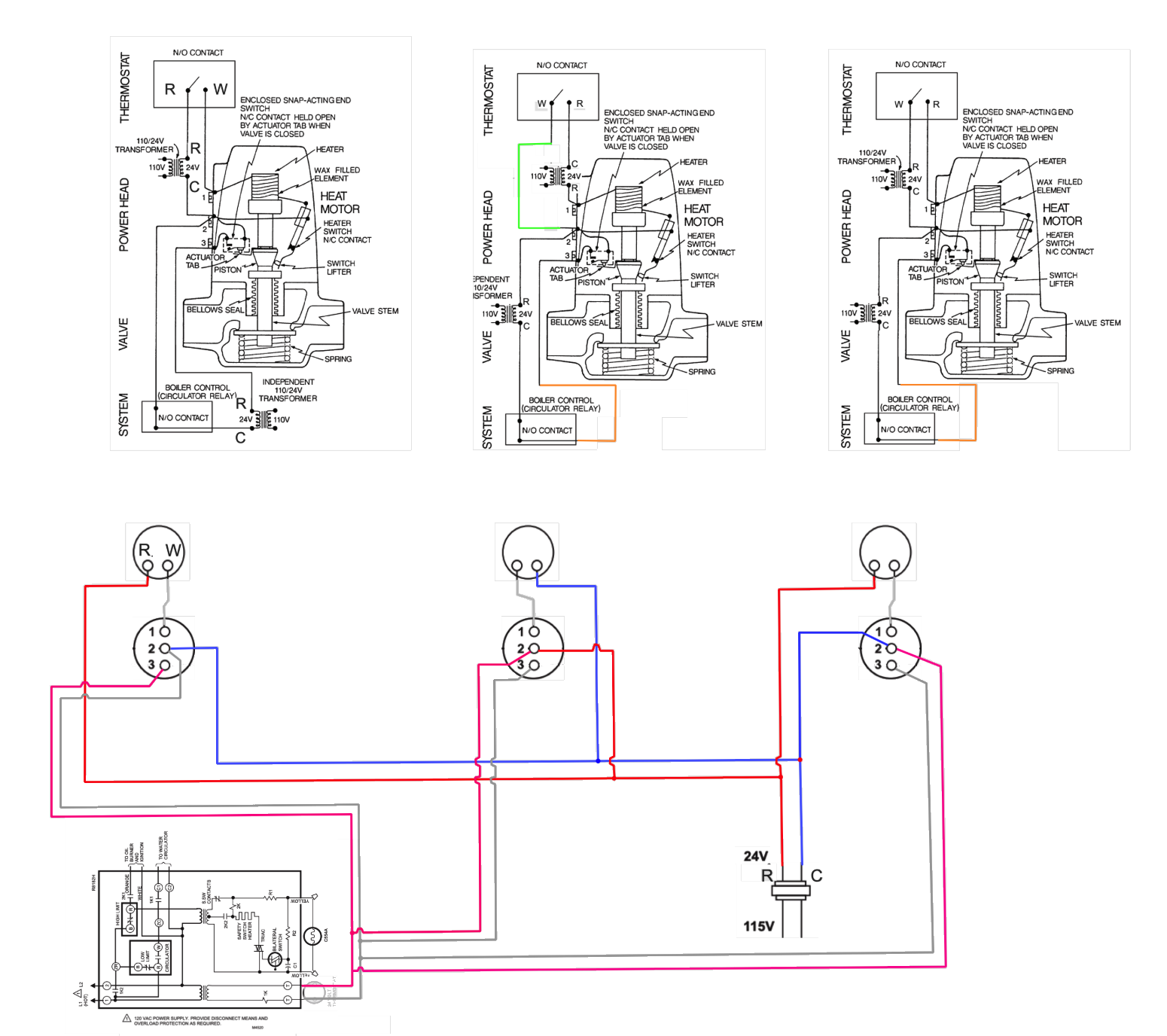
See how three correct methods when used on the same system will fry the transformer? R to # 2 and C to #2 on the same system will eventually cause R and C to be connected without a load between them so the smoke is let out.
Edward Young Retired
After you make that expensive repair and you still have the same problem, What will you check next?
3 -
This part of the Taco document below explains it. If this this does not makes sense to you, you need to better understand how transformers provide Galvanic Isolation.
The " 1 and 2, the reading across them tests at 7.8 volts " is may either be a circuit defect (if it is not working correctly) or the result of a power robbing thermostat that probably does not have a C wire installed. The 7.8 Volts may also may be result of slight leakage current due to the Capacitive Reactance of the wiring and transformers involved, commonly called a Ghost Voltage.
The heater (wax motor) does not need power 100% of the time the keep the zone valve open the switch provides the appropriate duty cycle to the wax motor so the valve remains open and the wax motor does not overheat causing damage.
Just to be clear there is two switches one between terminals 2 and 3 the End Switch and a second switch that controls the heating duty cycle of the wax motor with slight valve pintle movement.
 National - U.S. Gas Boiler 45+ Years Old
Steam 300 SQ. FT. - EDR 347
One Pipe System2 -
Zone relay boxes make it simple to wire most any ZV, and with a fuse protected transformer for errant mis wiring.
Readimng the directions helps regardless of which method you use.
 Bob "hot rod" Rohr
trainer for Caleffi NA
Living the hydronic dream3 -
@109A_5 , the isolation relay makes it foolproof.
Baltimore, MD, USA
Steam, Vapor & Hot-Water Heating Specialists
Oil & Gas Burner Service
Consulting1 -
Yes, I agree. The relay just provides another layer of isolation. Also adds more stuff to fail and more wiring to confuse folks even more. However maybe ultimately easier to repair without screwing it up and smoking transformers. The multi Zone relay boxes may be the best compromise, other than the extra cost.
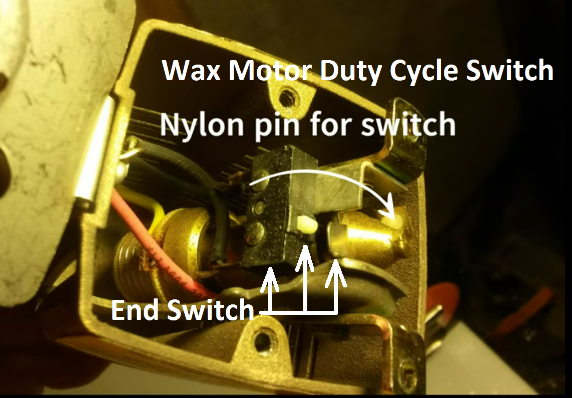
I have not found the animation video yet, but what is funny is the YouTube folks are confusing the switch functions. The tab actuator is the End Switch, The conical part is for the Wax Motor duty cycle.
 National - U.S. Gas Boiler 45+ Years Old
Steam 300 SQ. FT. - EDR 347
One Pipe System0 -
The duty cycle switch is opposite the micro/end switch. It is more like a reed switch or contact points. It rides against the cone shaped end of the wax motor "piston"
The micro/end a switch rides against a tab to activate.
I agree the few You Tube videos I watched are not exactly correct in their explanation. Several seem to think a single switch is inside?
This is why, for me , dissecting a mechanism better helps see what is going on.
 Bob "hot rod" Rohr
trainer for Caleffi NA
Living the hydronic dream1 -
I’m curious if the duty cycle switch and the end switch open and close in unison which may lead to boiler short-cycling and/or confusion when looking at the end switch lights on a zone valve control turning on and off.
Or is there a built-in delay on the end switch?
Bell & Gossett has a similar 3-wire, heat motor zone valve. Do they go through the same contortions to prevent overheating or over-extension of the piston?
8.33 lbs./gal. x 60 min./hr. x 20°ΔT = 10,000 BTU's/hour
Two btu per sq ft for degree difference for a slab0 -
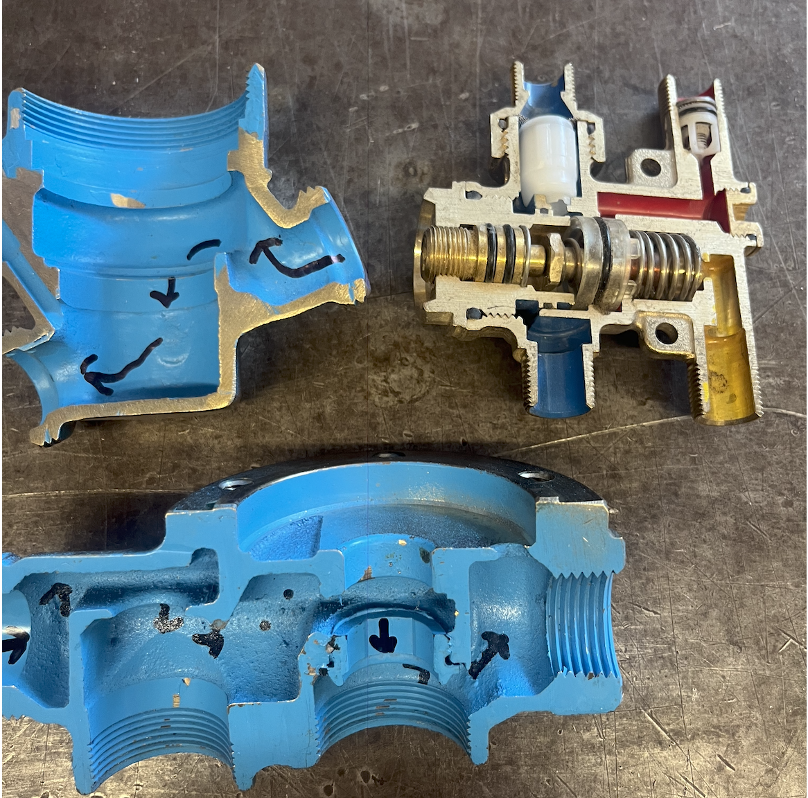
Not to me!
I consider cutaways an excellent training tool. Most hands on people like to know what is happening inside. We get a lot of ah ha moments.
Cut one open for training your own team if nothing else.
Caleffi produces dozens of cut away cases every year for reps and wholesalers. The trade schools snap them up also.
I clamp my PortaBand, with a coarse blade for soft metal, in the vice to slice open these valves. Spray paint, clear coat them.
 Bob "hot rod" Rohr
trainer for Caleffi NA
Living the hydronic dream 4
4 -
The end switch on those things is controlled by a different cam, @RayWohlfarth , and makes before the heater switch starts to function. It should remain closed during the heater cycling.
Br. Jamie, osb
Building superintendent/caretaker, 7200 sq. ft. historic house museum with dependencies in New England0 -
You need to use a good relay known for its reliability. I like these:
https://www.supplyhouse.com/Resideo-R8222B1067-24V-General-Purpose-Relay-with-SPDT-Switching
If your transformer mounts on a 1900 box, you can replace it with a transformer/relay (a.k.a. fan center) unit, which uses the same relay. This makes the wiring a lot neater. Your terminal 3 outputs go to G on the transformer/relay, and the Normally Open relay contacts connect to TT on the boiler. You'll have to route the wires from the N.O. contacts out of the box through a bushing and connect to the thermostat wire from the boiler outside the box, since thermostat wire is not rated for the higher voltages found inside the box:
I like those zone valve panels too, but there isn't always room for one.
Baltimore, MD, USA
Steam, Vapor & Hot-Water Heating Specialists
Oil & Gas Burner Service
Consulting0 -
If I were making a cutaway learning tool, I'd add LEDs or maybe some of those cheap eBay voltmeters to show what's going on electrically.
0 -
@Alan (California Radiant) Forbes I have not had the opportunity to cut one open to watch it function. However the way the switch placement looks to me, the tab will move off of the micro-switch's actuator first as the wax motor warms up. As the wax motor shaft moves further out and the wider part of the conical part of the motor shaft pushes enough against the actuator of the leaf switch the current through the heating element is shut off. As the heating element cools the motor shaft will eventually start to retract causing the leaf switch to close again adding heat to the wax motor.
The shaft of the wax motor moves slowly. I do not believe in normal operation the minor cycling (oscillation) of the motor shaft will cause cycling of the End Switch.
National - U.S. Gas Boiler 45+ Years Old
Steam 300 SQ. FT. - EDR 347
One Pipe System1 -
LEDs are an excellent visual aid that helps express what is happening electrically.
National - U.S. Gas Boiler 45+ Years Old
Steam 300 SQ. FT. - EDR 347
One Pipe System0 -
I agree with @Steamhead using a relay does make them foolproof and you don't have to worry so much about the wiring being mixed up.
I prefer the rib relays because the pilot light tells you what is going on.
Besides with two transformers intermingled you or I may know what is going on but many people do not.
2 wires to power the valve and two wires for the end switch make more sense to me.
0 -
The relay type @Steamhead specified is fine but with a system like @JohnNY described with 36 zones using that relay type and the associated wiring and fan center transformers could turn into a huge mess unless the installer does an amazing wiring job. Often HVAC wiring is a disaster. Relays do have their place, however they do fail in strange ways.
National - U.S. Gas Boiler 45+ Years Old
Steam 300 SQ. FT. - EDR 347
One Pipe System0 -
@JohnNY You said, "When connected to 1 and 2, the reading across them tests at 7.8 volts and the valve doesn't open.".
How many volts do you read on a good valve?
8.33 lbs./gal. x 60 min./hr. x 20°ΔT = 10,000 BTU's/hour
Two btu per sq ft for degree difference for a slab0 -
I would expect a good valve should have 24 VAC (nominal) across terminals 1 and 2 when the thermostat is calling. Was the thermostat actually calling ? This should not be too hard to troubleshoot, power source, control, load and wires. Also it may have nothing to do with the 3 terminal type zone valve circuit.
Another thing that is a possibility to suspect, does the heater coil in the zone valve have a defect and it is overloading the transformer.
As @hot_rod shows above a clamp on ammeter may help in the troubleshooting process. Or a substitute actuator.
Compare actuator heater Ohmmeter readings.
National - U.S. Gas Boiler 45+ Years Old
Steam 300 SQ. FT. - EDR 347
One Pipe System0 -
ZV, RIB, transformer, box to mount it on, around 200 bucks. Wiring, labor X 6 zones= ?
I think for simplicity, labor hour and parts, a relay box makes a lot of sense.
 Bob "hot rod" Rohr
trainer for Caleffi NA
Living the hydronic dream0 -
How many of these zone valve can you run on a relay panel before its transformer is overloaded?
0 -
The TACO 6-zone panel (ZVC-406-5) has an 80VA transformer, so it has enough juice for 6 zone valves.
Baltimore, MD, USA
Steam, Vapor & Hot-Water Heating Specialists
Oil & Gas Burner Service
Consulting0 -
I don't deal with these actuators all that often but I'm inclined to answer that I typically see 24v across 1-2 when the thermostat is calling and the zone is energized.
Contact John "JohnNY" Cataneo, NYC Master Plumber, Lic 1784
Consulting & Troubleshooting
Heating in NYC or NJ.
Classes1 -
That's because terminal 2 is typically connected to R on the transformer. With the thermostat contacts open, the lead between terminal 1 and the thermostat will show 24v to ground (or to C on the transformer) since there is no path to C through the thermostat. But when the thermostat closes, the lead between 1 and the thermostat will show zero, because the load (the heat motor) now absorbs the voltage out from 1.
We sometimes find the same in old knob-and-tube wiring. There was no polarity in the early days, so sometimes a light switch ended up in the neutral wire instead of the hot. It controlled the light just fine, but it meant the socket was still hot even when the light was off, which could electrocute someone changing a bulb. If we measured voltage to ground (which could be a cold water pipe) on such a circuit, we'd find 120v on one switch terminal when the light was off, but zero on both terminals when the light was on, for the same reason. And don't get me started on those "Carter circuit" 3- and 4-way switches that alternated between the hot and neutral……….
Baltimore, MD, USA
Steam, Vapor & Hot-Water Heating Specialists
Oil & Gas Burner Service
Consulting0


Categories
- All Categories
- 87.7K THE MAIN WALL
- 3.3K A-C, Heat Pumps & Refrigeration
- 59 Biomass
- 430 Carbon Monoxide Awareness
- 129 Chimneys & Flues
- 2.2K Domestic Hot Water
- 5.9K Gas Heating
- 122 Geothermal
- 170 Indoor-Air Quality
- 3.8K Oil Heating
- 79 Pipe Deterioration
- 1.1K Plumbing
- 6.6K Radiant Heating
- 396 Solar
- 16K Strictly Steam
- 3.5K Thermostats and Controls
- 56 Water Quality
- 51 Industry Classes
- 51 Job Opportunities
- 17 Recall Announcements