Snow Melt System Problems, pump too small?

At my house we installed a hydronic snow melt driveway about 2 years ago, we haven't had a big storm in that time to really test it until this week, and I think it needs some tweaking. I'm looking for any help as I've never done anything with HVAC before (I am an engineer but primarily structural design)
Some loops are melting with no issues, but others aren't hardly melting at all, the supply temp is calling for 120 degrees based on the current air and slab temps, but the return temp in the manifold is only 70, so there is a temperature drop of 50 degrees. The loops that are melting fine are all at one end of the manifold, checking them with a infrared thermometer the one at the end of the manifold is returning around 88 degrees, then with each loop along the manifold the return temp drops a few degrees, and by the last loop its only returning at 50 degrees.
It was installed by a plumber that we use on commercial buildings (he does a lot of commercial and hospital work), and he had it designed by the local large distributor who also supplied the system. We installed a similar system 10 years ago at my fathers house and they designed it for him as well, they gave him a design and drawings, but this time it was a different person from them that did the design and never gave us drawings, just told our plumber how many zones, the loop lengths, sizes, and sold him the pumps, manifolds, and boiler he said it needed to work.
I am now trying to reverse engineer the system to figure out how to correct it and my plumber is reaching out to the person that designed it for input as well.
These are the specs as isntalled:
Driveway square footage: 3200
Tubing: 3/4" PEX
Loop Length: 300'
Number of Loops: 12
Total Tubing Length: 3600'
Spacing: 12" OC
Boiler output: 400,000BTU mod-con
Controller: Uponor Single Zone Snow Melt Control (Looks identical to the Tekmar 670 Control at my parents house)
Manifold: Uponor Truflow Manifold
It's plumbed with a Primary-Secondary loop setup.
Boiler loop Pump: Taco 0013
Circulating Loop Pump (to manifold): Taco 0014
Based on how it's acting I'm thinking it isn't getting enough flow through the manifold/loops to get the proper return temps in all the loops.
I just read the Uponor Snow Melting Design Manual and filled out the Design Worksheet Which I've attached along with the appendices that I used and I'm finding the following:
for a 10 degree design temp, 10mph wind, I need 107 BTU/h/ft^2, which results in a total BTU/h of 342.400 (ok for my boiler).
For the 3/4" Pex with 300' loops with a glycol percent of 50% i need a flow of .0099gpm/ft, or 2.97 GPM/loop
Going by the Appendix for this flow rate it gives a head loss of .06869 per foot of tubing, for a head loss of 20.6 feet of head.
is saying either 22.4' or 21.4' of head loss based on 120 or 130 degree water temp. So they are giving similar results
Based on the head loss I'm not seeing the Taco 0014 as being capable of pumping this system at all really, the curve looks to give it about 1gpm at 22' of head loss, even the 0013 that on the boiler loop only gets 15gpm at 22' of head loss, so it's not like they accidentally swapped the pumps during the install. The 0014 has a max flow of 32GPM and that's with no head loss.
Is there a pump that can get me the appropriate flow of 36GPM at 22' of head loss?
Are my calculations correct?
It looks to me that the Taco 2400-50-3P or the 2400-70-3P could have just the right amount of flow for the head loss I am calculating, could anyone comfirm this?(https://www.tacocomfort.com/product/2400-series-high-capacity-circulators/)
I am waiting to speak with the person that designed it from the supplier but I want to try to come up with a game plan to improve the efficiency of this system.
Comments
-
you will have a really wide delta T on a cold start, 50 degrees is not crazy 12" on center spacing will make your required supply temperature greater, I would turn that up. the main thing is you have a few loops that seem to be not circulating? I would check to make sure they aren't closed, either at the black cap shut off for the loop, or the flow meter tightened all the way down before looking at more technical info. I'm using typically 3/4"or5/8" at 6-9" on center typically I would expect some striping in my area on 12" centers but it can work.
I would also want to know for sure you have 50% glycol, if you just took off the shelf buckets of say no-burst or similar and mixed half and half with water your actual glycol % will be less than 50%. the buckets are somewhere around 70% ish I think off the shelf unless they say RTU-30 etc
Looking at that pump curve there is no way you will get 36GPM at all out of it. If your flow meters are set for 3GPM you very well may just be flowing through what the pump is capable of flowing. I would still check to make sure nothing is closed off, but it does sound like you need more pump. Those pressure drop calcs also do not take into account the manifold pressure drop, or the supply and return tube pressure drop.
 1
1 -
where is this located? The 50% glycol is driving the pump spec up a bit
Using the PPI calc at the designed 2.97 gpm
35%=22’
40%=23’
50%=26’
107 btu/ sq ft is on the low end, but again based on snowfall and rate of melt you expect in your area.
A class 1 system
Bob "hot rod" Rohr
trainer for Caleffi NA
Living the hydronic dream1 -
Long Island, NY
A large storm for us is over 1', 18"-2' is a huge blizzard.
We got about 18" this past Saturday into Sunday and it hasn't been able to fully clear the final 4 loops on the manifold (its just melting some barely which is refreezing into ice between the tubing) meanwhile everything else is fully dry and has been for a day, they're just not getting enough flow in all the loops.
0 -
And as I said the boiler is 400,000BTU so at 3,200 ft^2 it can put out 125btu/sq ft. Its just a matter of getting sufficient flow.
I'm looking at the Taco 2400-50 pump because it's only 1/8" different in length from the 0014 that's currently there and would be and easy swap out as we have a valve directly on both sides of the pumps, so if that'd be a fix or at least significantly improve performance I'd be up for trying that versus replumbing everything.
0 -
it could be some air locked loops, or longer lengths maybe. Hopefully not kinked tube
ASHRAE has different classifications of SIM designs based on snowfall and expected rate of melt
I guess it depends on what the designer was asked to design to? 100- 125 is typically a Class 1 system the lowest melt rate.
Regardless, the system you have will need the gpm and SWT the design shows to get you the 107 Btu/ ft
Bob "hot rod" Rohr
trainer for Caleffi NA
Living the hydronic dream0 -
Do you have flow meters? can you dial back the flow meters to somewhere around 2GPM and see if the system balances out better? I'm still thinking you just don't have enough pump. The freezing between loops thing is why I always tell the contractor 9" maximum spacing, I know it can work with wider but our customers up here are very demanding. we always design around 150 btu/sqft and makes sure the system can deliver that if needed.
 2
2 -
All the loops were fully purged, no lines were kined when the concrete was poured.
The temperature drop is linear from one loop to the next along the return manifold, each return loop is about 3 degrees cooler than the one next to it. So the loop at one end of the manifold returns around 88 degree, the loop at the other end of the manifold is around 53 degrees.
I started the system 12 hours before the snow and it never better than a 50 degree average delta T (an average return of 70).
It doesn't just seem to be one loop, it seems like the pump just doesn't have the push to supply all the loops leaving the manifold.
0 -
does your manifold have flow meters that you can dial back to around 2GPM to see if the system will balance out until a contractor is able to install a more suitable pump?
1 -
It doesn't have flow meters sadly (at my parents house that manifold does).
It has Uponor Truflow ManifoldsThey do seem to offer a flow meter for them but I'd have to be installed between the manifold and each supply loop, and they only seem to offer them in a 2.0 GPM max size .
The loops at the one end of the manifold that are getting bettwe return temps have no issue with freezing between the loops, it's only the ones struggling with the return temps/flow that are having an issue.
1 -
I wonder if the supplier just fat fingered the pump model? It's weird they wrote down so much info and then selected a pump that has a listed max flow and max head both below your required numbers. I'm sure when you explain it someone will try to make it right for you. That can't have been a cheap system.
0 -
Are the poorly performing loops the furthest from the manifold? It sounds to me like the loop lengths just get longer and longer, so the flow is getting lower and lower.
Can you choke down the warmer 2-3 zones a little to see what happens?
0 -
I filled out that Worksheet based on how it's installed, IDK how the supplier determined the pump size.
1 -
Oh good to know. If you have a single 1-1/4" pipe size manifold your max flowrate is 21GPM BTW. and getting near that flow rate will add a bunch of pressure drop. Your manifold may not have flow meters, but it does have balancing valves that you can use to balance the loops a little. If you have a couple short loops they will be easier to flow through, longer loops more pressure drop, water is lazy so it takes the path of least resistance, if the balance valves are wide open those open loops may be able to balance down a little
pg2 for balance instructions
0 -
The loops are all the same length, the ones at one end of the manual come out of the house and go left, they go a pretty far distance and come back without many turns, they are the hottest and best working loops. Then as you get near the middle of the manifold they go more just in front of the house and make more surpentine turns before coming back (these have the middle return temps), then at the right end of the manifold the loops go out the house and to the right, they go a bit of a ways as well without as many turns and come back (just as the ones on the left side of the manifold do) but these have the lowest return temps.
The supply comes into the manifold from the right side, my theory is that the flow comes into the manifold, fills the length of it, then starts going into the loop furthest into the manifold (theses are the ones with the highest return temps) then as you go back down the manifold towards the supply it has less pressure left to push the fluid into each subsequent loop, until you get the the furthest right loops which are getting the lowest flow.
0 -
The manifold set up , the first loops heat well and the end loops do not ?
There was an error rendering this rich post.
0 -
No the end loops (at the dead end of the manifold) heat well and the first loops nearest the supply do not.
0 -
Yeah and now that you mention it they did have one thing weird when they were installing it, they said they didn't have a 12 loop manifold in stock so they gave us a 7 loop and a 6 loop and had us take the end off one and connect them in series and then just not use one of the connections.
I'm wondering if he sized is at a 7 loop manifold (7 loops x 3 GPM= 21GPM) then realized he messed up and just had us combine it with another 6 loop manifold without taking into account the max flow.
This sucks so now it's looking like I'll have to swap out the manifold at some point as well as the pump.
Or I guess we could replumb it to have it as 2 manifolds, a 6 loop and a 7 loop.
0 -
Post some photos of what you have . maybe we can find something….
There was an error rendering this rich post.
0 -
Air-Bound...You may THINK you have all the air out. Pictures of the boiler and piping? Mad Dog
0 -
Well more pump gets you more output. That is an easy upgrade option. But doesn't increase the boilers output capacity.
At some point the performance limit becomes boiler size 400,000 at say 92% efficiency =368,000 actual BTU
With 3200 sq ft of SIM you could move around 368,000 ÷ 3200= 115 btu/hr into the slab with that boiler.
Cold glycol is tough to pump, so as RWT goes up the glycol is thinning and getting easier to flow. So it takes time to ramp up the mass.
A 5" slab needs @ 10 btu/hr./ sq ft to increase 1°F
3200 sq ft @ 5" slab is about 46 yard of concrete X @ 4000lbs/ yard=184,000 lbs of concrete X .21
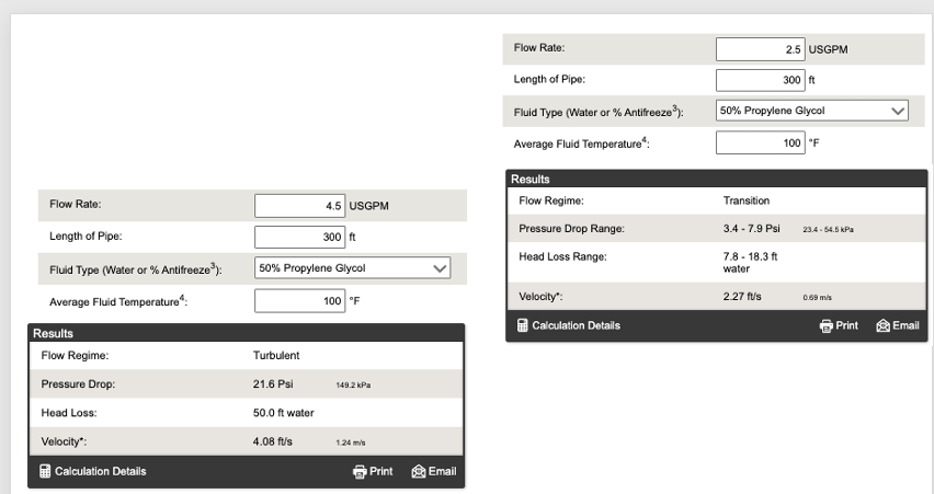
If you had a measured accurate flow number
BTU = 442 X f X ∆
Example below of 3/4 pex at 4 fps velocity limit
and more reasonable 2.5 gpm= 18' head
 Bob "hot rod" Rohr
trainer for Caleffi NA
Living the hydronic dream0 -
Try shoveling most of it
Where on LI is there 18”
0 -
Knowing you have 1-1/4 manifolds ad the branch size of them, you may need to go with the output you currently have.
With enough horsepower you could shove 36 gpm through a 1-1/4 tube, but at 8.8 fps velocity, not a good number.
If ever you go that route, a plain simple copper tube manifold is all you need for SIM. No need for anything fancy if you are not balancing or zoning.
Bob "hot rod" Rohr
trainer for Caleffi NA
Living the hydronic dream0 -
so I spoke with the person from the supply company and he seems to agree the pump is undersized. He said the 0013 pump is sized for that boiler, but he doesn’t know how I ended up with the 0014 pump to circulate and that it doesn’t have the power needed in the system. He recommended trying g the 2400-50 pump I was mentioning to see if that gets the correct delta T.
I asked him about the 21GPM max of the manifold and he said he’s never had an issue with that and that they have other clients running the 2400/50 pump into a 12 loop manifold sized similar to my system.he actually said they have one customer near me with a much larger system, they have 2 of the same boiler as me, 3 manifolds each with (12) 300’ loops of 3/4 pex and have a 2400-50 pump on each manifold and that it’s been working great for 12 years.
so I’m gonna start with changing out the pump and see if that improves the performance enough. He’s checking stock and if they have one I’ll swap it out by the end of the week. We have a valve on both ends of both pumps so to change out the pump is easy.
0 -
I’m not sure “ he’s never had an issue” is a response an engineer would accept?
Plenty of places to find flow charts/ velocity charts online. I use the engineeringtoolbox website
At the least get Uponors opinion on 36 gpm through a 1-1/4” manifold with a 21 gpm max. rating
Reducing pipe size basically results in velocity increase through the restriction
That being said the infrequent use of the system it may last for many years before flow velocity erodes it away.
I won’t hear it at my house.
The pump curve doesn’t tell you what flow you end up with.
An OP operating point is developed by overlaying the system curve on the pump curve, where the lines cross is where the system actually operates
I would swap the pump and call it a day🫢
Bob "hot rod" Rohr
trainer for Caleffi NA
Living the hydronic dream1 -
I could go on an on about this one but its not going to help the issue 😁. I agree with Bob, change the pump for an appropriate one and the system should function how you need it to.
0 -
also use the glycol % correction when you size the pump.
Bob "hot rod" Rohr
trainer for Caleffi NA
Living the hydronic dream0


Categories
- All Categories
- 87.6K THE MAIN WALL
- 3.3K A-C, Heat Pumps & Refrigeration
- 59 Biomass
- 429 Carbon Monoxide Awareness
- 124 Chimneys & Flues
- 2.2K Domestic Hot Water
- 5.9K Gas Heating
- 119 Geothermal
- 168 Indoor-Air Quality
- 3.8K Oil Heating
- 78 Pipe Deterioration
- 1K Plumbing
- 6.6K Radiant Heating
- 394 Solar
- 16K Strictly Steam
- 3.5K Thermostats and Controls
- 56 Water Quality
- 51 Industry Classes
- 50 Job Opportunities
- 18 Recall Announcements