Circulator noise when hot?

Hi everyone!
A new taco 0010 was installed on my hydronic heating system. I’m noticing a strange noise only when the circular is circulating hot water (not when the boiler is off on mild days and just circuiting cooler water).
Not sure how I can share the nose here in the forum. It’s a random knocking sound the is coming from the circulator. Not loud but noticeable.
I’ll try to find a way to share the sound.
Thakar for any help!
Comments
-
what type if system? Boiler? Heat emitters?
What is the pressure on the boiler gauge? 12- 15 psi cold is a range
A pic if the piping could help.
With low pressure and high temperature you could be getting some cavitation noise
Bob "hot rod" Rohr
trainer for Caleffi NA
Living the hydronic dream 2
2 -
@hot_rod thank you.
CG8 (202,000 output)
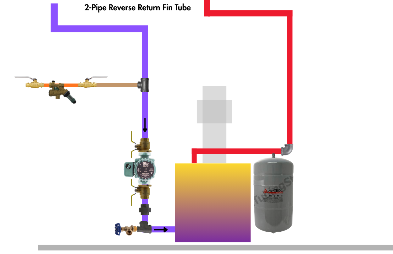
2 pipe reverse return.
circulator on the return.
expansion tank on supply.Cold is 15psi
Hot is 19psi or so
Fin tube
Delivering heat well.
0 -
if the circulator is too big for the piping or a valve is mostly closed or a strainer or something is clogged, it could still be cavitation.
 1
1 -
@mattmia2 thank you.
if the pump is too large, how does the temp of the water increase this possible cavitation issue? No noise when water is cooler.
The previous pump was a series 100.
I believe the head and flow needs are in the ballpark for the 0010.Thank you!
0 -
Cavitation is a basically a function of temperature and pressure. The hotter the water the easier it is to cavitate because it's already closer to the boiling point. Likewise insufficient NPSH for the pump at its operating point on the curve also makes it possible to cavitate in the eye of the impeller because that's where the pressure drops as the pump pulls the water in. When the pressure drops low enough for the water at that temperature to vaporize, then you have cavitation.
What does the noise actually sound like? does it sound like rocks in your pump? that's the lovely classic cavitation sound.
Off the top of my head I think the 0010 curve is pretty similar to a series 100, but I also don't usually deal with small pumps like those
1 -
any flo-checks in the system. Those can make a tapping sound
Look for a partially plugged strainer, valve not fully open
Might pull the motor from the body and look for anything unusual
Maybe a warped impeller that expands and rubs when hot?
It seems like a high flow circ, which would be correct for that size boiler
Bob "hot rod" Rohr
trainer for Caleffi NA
Living the hydronic dream0 -
thank you @pumpcontrolguy .
This explanation makes sense to me.
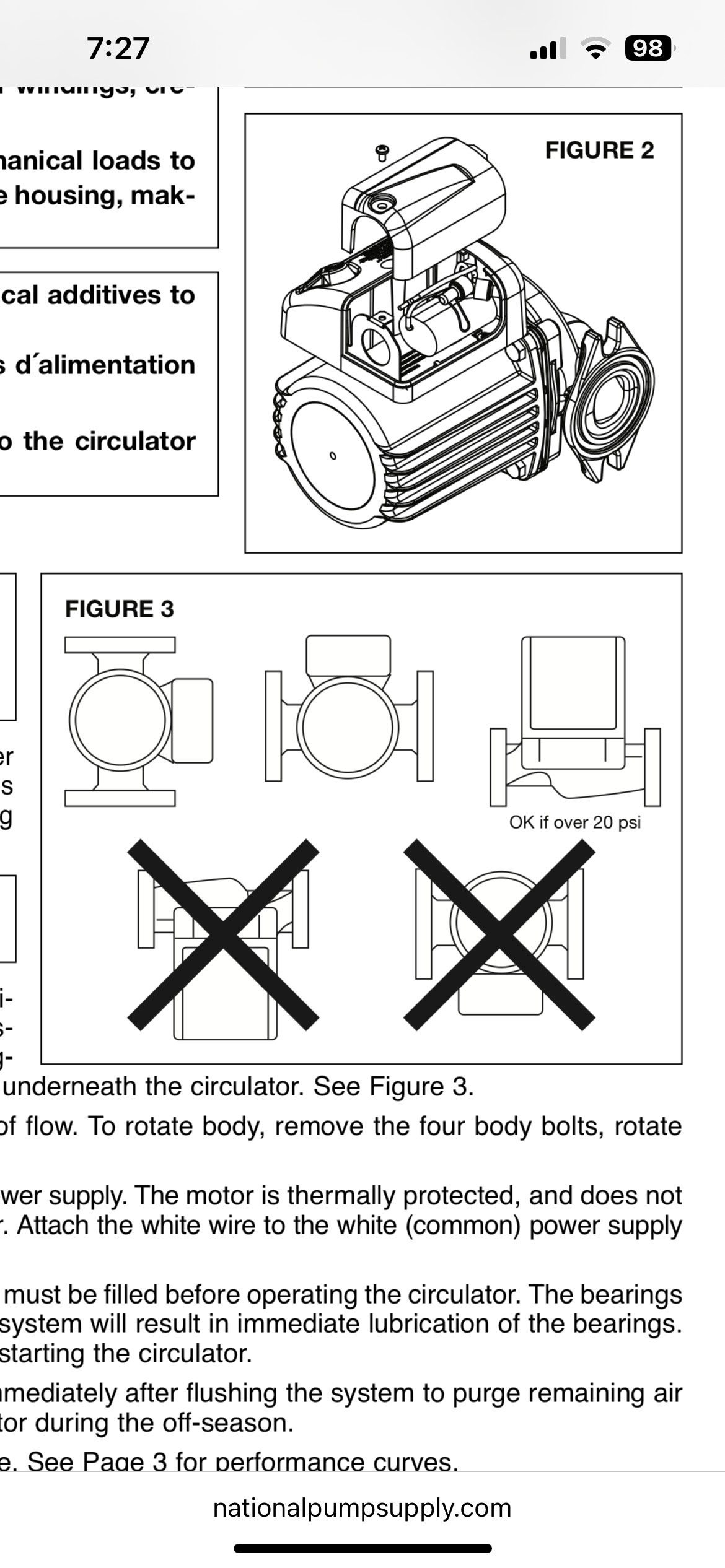
I did notice that that motor body (logo) is upside down yet the flow arrow on the body is facing the correct direction.
Does the motor body direction matter with these wet rotor type circulators?
0 -
 Bob "hot rod" Rohr
trainer for Caleffi NA
Living the hydronic dream0 -
"circulator on return, expansion on supply" "noise only when hot"
Equals cavitation. There are other potential problems — but the overall bottom line is that most of your pressure loss in the system is between the expansion tank and the inlet to the pump — so the pressure at the inlet to the pump is a lot less than the "system" pressure, and when the water is hot, it boils — cavitates — at that low pressure.
All the above suggestions are good — but move the expansion tank to the inlet of the pump and live happily ever after.
Br. Jamie, osb
Building superintendent/caretaker, 7200 sq. ft. historic house museum with dependencies in New England
 3
3 -
vapor pressure is what is at work with some cavitation. It is the pressure required to prevent water from flashing to steam. There is a pressure drop at the inlet "eye" of the impeller, if it drops below the vapor pressure of the water at the temperature it sees, then vapor pockets form.
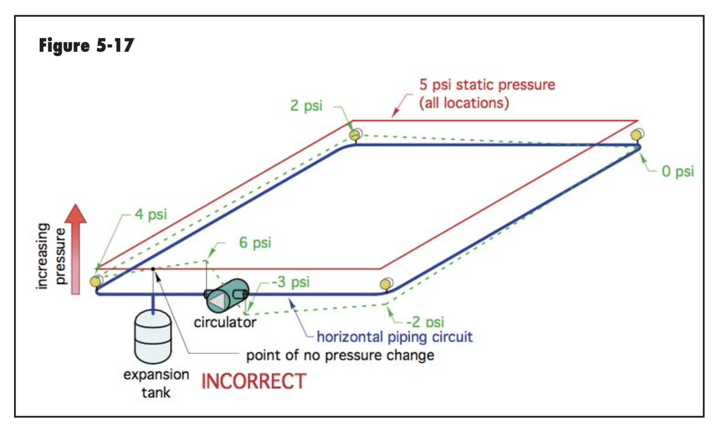
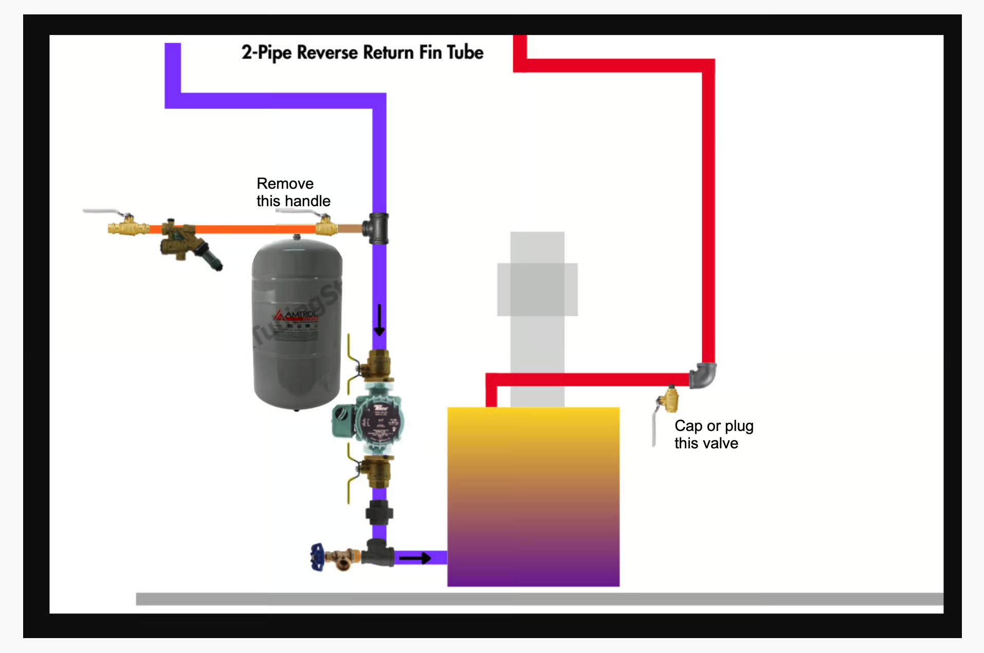
The piping schematic belows shows what can happen when you pump at the expansion tank, the PONPC. If the circuit allows the pressure to drop below the vapor pressure, that is where cavitation starts. Notice the negative pressure at the circ inlet.
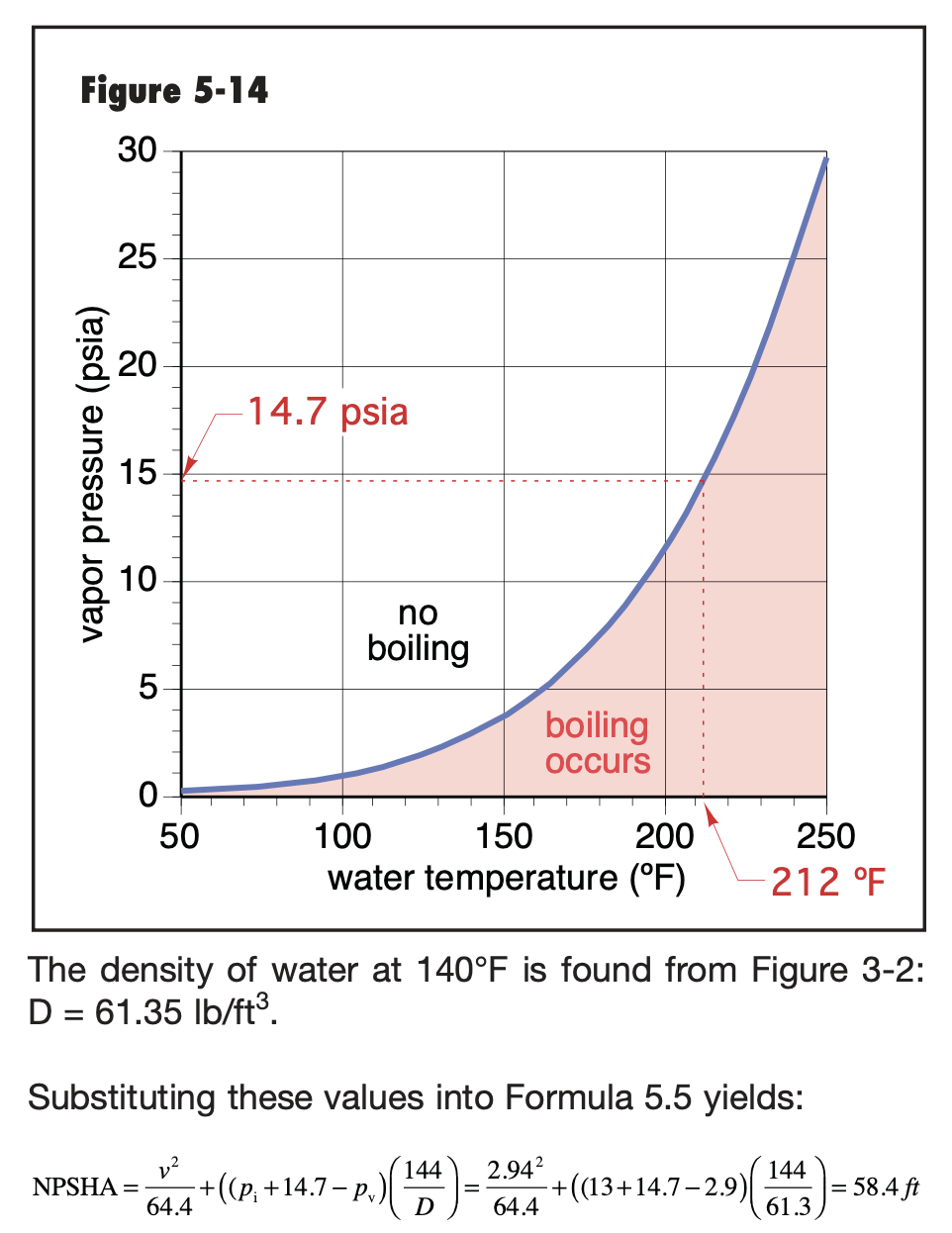
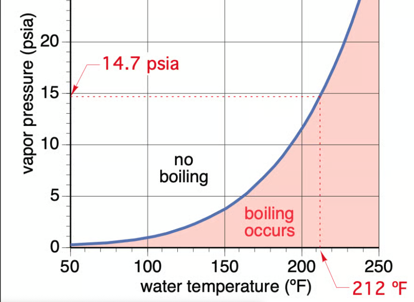
The graph shows the pressure temperature relationship. Yes water can boil at 100°F. That is how evac tube solar collectors work. The vacuum on the fluid allows it to boil around 100°
At sea level pressure is 14.7 PSIA, water boils at 212°F.
Water boils at around 202°F in Denver at 5,000'
 Bob "hot rod" Rohr
trainer for Caleffi NA
Living the hydronic dream0 -
thank you, @hot_rod .
this didn’t seem to be an issue with the series 100 in the past. Is there anything I could do to remedy this with the piping? Unfortunately, unable to pump away at this time.
0 -
@hot_rod , @pumpcontrolguy @Jamie Hall @mattmia2 , here is a link to the audio of the noise.
0 -
The two pumps have different intake pressure requirements.
As a temporary fix — mostly to avoid further damage to the pump —- you could try boosting the entire system pressure. But… you have to keep a margin below the safety valve,
Br. Jamie, osb
Building superintendent/caretaker, 7200 sq. ft. historic house museum with dependencies in New England0 -
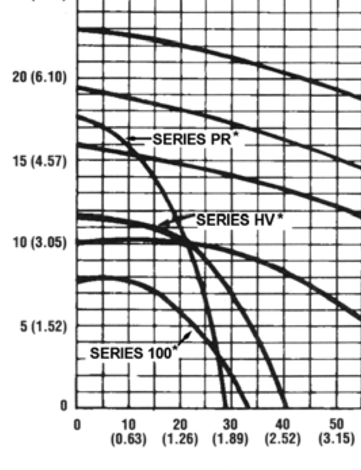
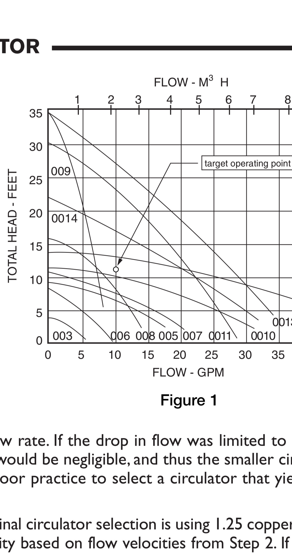
yes the 0010’is a bit higher head circ, here are the two curves
The left vertical axis is shut down head. The head the circ would develop if it were moving 0 gpm, the lower horizontal axis
The series 100 is around 8’, the 0010 around 12’
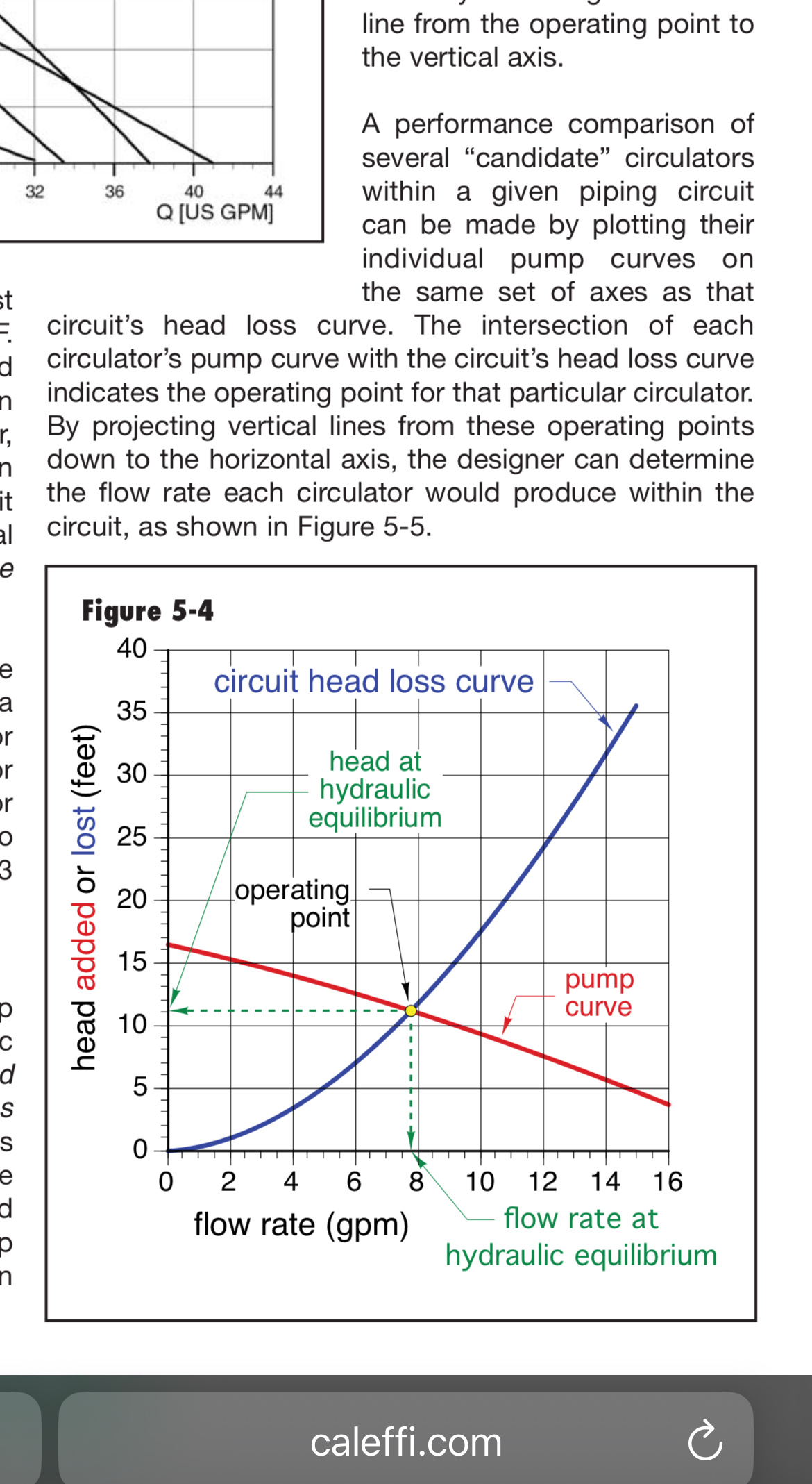
You would need to define the circuit it is connected into to develop a system curve, example below.
The system curve lies over the pump curve to determine the OP, actual operating point. Could be the 0010 is just a bit higher head and causing the issue
If it is cavitation two things could correct it, raise the static pressure as @Jamie Hall mentioned, or lower the water temperature
Is there a valve on the discharge of the pump, maybe an iso flange? If so you could throttle away some of the head .
 Bob "hot rod" Rohr
trainer for Caleffi NA
Living the hydronic dream0 -
does it have the integral flow check? that could be chattering.
if it is a single zone and doesn't have a dhw zone you can take the flow check out.
0 -
-
Gosh that pump isn’t that far off from the B&G. My next step would be to pull it. All sorts of stuff can end up in pump impellers
Bob "hot rod" Rohr
trainer for Caleffi NA
Living the hydronic dream0 -
thanks @hot_rod . Yes, I’m going to take a look at the impeller. Good idea.
Should I be concerned with this adding air to the system when I remove the motor body?
0 -
are there isolation valves on both sides of the pump? That minimizes the potential to allow a lot of air in.
I always leave the assembly bolts a bit loose and let the air burp out, then tighten the motor back in
Bob "hot rod" Rohr
trainer for Caleffi NA
Living the hydronic dream1 -
Hmm, that doesn't really sound like cavitation to me. more of a vibration of some sort. I'm not super familiar with these little wet rotor circs, but my immediate thought is some sort of imbalance on the impeller/rotor.
1 -
@AlwaysLearning2024 If the B&G Series 100 was working properly, why not install a circulator that has a more closely related performance curve? Maybe a Taco 007? Or another wet rotor circ. that will do the job. It seems the better option rather than changing and repiping, and so on, etc. etc.
1 -
That is a good sized boiler, is this in a residence?
If you in fact need 172,000 BTU/ hr output then you need to move around 17 gpm.
If you need 17 gpm and it has zone valves the 0010 is a nice flat curve circ for the job.
You want to run a circ mid curve ideally, aka the "knee" of the curve.
You could count up the amount of fin tube, just the finned element to get an idea of the BTU you actually can move into the home.
500 btu/ft is a good average X the number of feet give you actual required btu
 Bob "hot rod" Rohr
trainer for Caleffi NA
Living the hydronic dream0 -
Thanks @hot_rod. This is a 4-family building.
@EdTheHeaterMan generously helped me work out the head and flow in the following post. I had to go with a 0010 and not the 0012/Series HV as Ed suggested.
This CG8 replaced a larger boiler in 1994 before I owned the building. The building is definitely plenty warm. Controlled by a TekMar 256.
0 -
thanks @Intplm. I thought the 0010 was a match but I must have been mistaken. Still learning so much here.
0 -
Sometimes plotting your system on a pump curve can be difficult when there are several different curves for many pumps. The fact that one brand uses a narrow pump chart and the other brand uses a flatter pump chart only confuses things. Only when you put all the pump curves that you are considering on the same chart, can you see the actual difference in each pump, and how that small change can affect your system. Here is that chart:
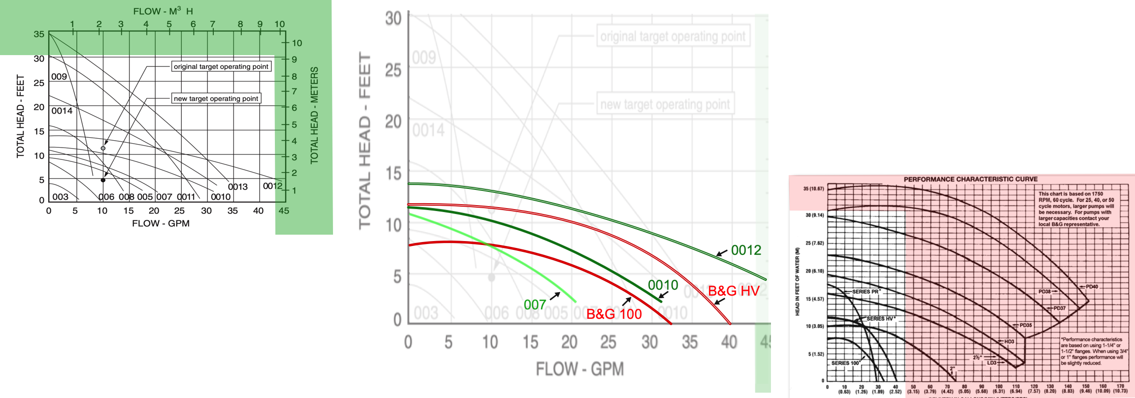
The left is the TACO and the right is the B&G published performance curves for several of their pumps.
In the center, I have flattened the B&G and made the TACO a little taller so all the HEAD and the GPM lines match up. Then I only selected the 5 pumps mentioned in this discussion. TACO 007, B&G 100, TACO 0010, B&G series HV, and the TACO 0012. When all the performance curves are lined up on the same chart, you can clearly see that the TACO 0010 has more pumping ability than the B&G 100. This may not be by much but perhaps just enough to cause your noise cavitation at the higher temperatures.
When throttling a ball valve on the discharge side of the TACO 0010 pump to reduce the flow rate in order to better match the B&G 100 a 10 or 15% closure may have no effect on the flow rate. You may need to get closer to 70% closure of a ball valve in order to cause a real reduction of the flow rate. Then the smallest adjustments after that may cause a large reduction in flow rate. Ball valves are not the best devices for that purpose however that is what you have to work with, so you need to use them.
Important NOT to throttle the inlet side of the pump. That will make things worse. Only throttle the discharge side of a pump to meter the flow in the system
Hope this info helps
Mr. Ed
Edward Young Retired
After you make that expensive repair and you still have the same problem, What will you check next?
2 -
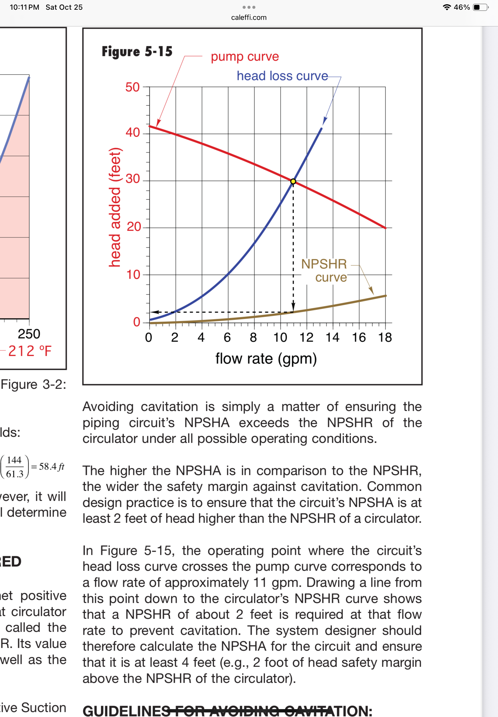
some pump manufacturers also add the NPSH curve into the graphs, generally on larger sized pumps.
Once you define the OP, the point of hydraulic equilibrium, which is the point where the head added matches the head loss of the circuit.
From that point drop down to the NPSH curve.
NPSH is the amount of head required to avoid cavitation. NPSHA is the head available
 Bob "hot rod" Rohr
trainer for Caleffi NA
Living the hydronic dream0 -
Thank you, @EdTheHeaterMan as always! Curious why I may be having a cavitation issue now after replacing the circulator with a Taco 0010. The pump is quiet when the boiler/piping is cool (on warm weather days). Sound gets louder as the boiler heating rises. The only change to the system was replacing the insufficient smaller Taco ECM with a more properly sized (I think…) 0010.
Thanks for any help!
0 -
more flow… more head losss… and with your piping, that means lower head at the pump inlet… which means more cavitation…
Br. Jamie, osb
Building superintendent/caretaker, 7200 sq. ft. historic house museum with dependencies in New England0 -
Also the higher the temperature, the more prone to cavitation.
3 guidelines if you suspect cavitation.
Keep system pressure high as possible
Lowest fluid temperature need to heat the home
Pump away from the PONPC.
Since you are pumping at the expansion tank, no easy option to change that??, the pressure at the circ's inlet is dropping and you get closer to the boiling point based on both pressure and temperature.
The graph attached a few posts up shows this.
Lets assume you run 170 fluid temperature, at that temperature you need about 8 psi at the circulator to avoid boiling or cavitating.
A gauge at the inlet of the circ would answer the question. If you have a static, no fluid moving pressure of 12 psi. The pressure drop around the circuit being circulated is WAG 6 psi. So the circulator inlet pressure would be 12-6=6 psi
Use that number on the left side of the graph below
Run across the graph to the right to see the fluid temperature intersection.
So the slightly higher head circ that you added, the fact you are pumping at the PONPC and your static pressure and highest operating temperature all factor to answer the question what could be causing the noise at higher temperatures.
You need to fill in some blanks, at what temperature do you start to hear the noise?
Also the pressure at the circulator inlet.That could be measured, or calculated with a few steps of number crunching.
Simpler yet, increase fill pressure and or reduce operating temperature. Does the noise disappear, then you have a cross check to what may be going on.
 Bob "hot rod" Rohr
trainer for Caleffi NA
Living the hydronic dream 1
1 -
Thanks @hot_rod and @Jamie Hall .
The circ is on the return, as well as the makeup.
The expansion tank is unfortunately on the supply.
I start hearing the sound around 130 degrees.
System pressure (according to the boiler guage, static pressure is around 15psi, when around 140 degrees, roughly 18-20psi). Unable to check the pressure at the inlet of the circ. The expansion tank has a service valve.
 0
0 -
How easy would it be to do this?
This new expansion tank location would solve your problem.
Edward Young Retired
After you make that expensive repair and you still have the same problem, What will you check next?
0 -
With the numbers you posted, I’m not thinking cavitation, 130f, 15 or higher psi and a fairly low head circ.
If somehow you established a high pressure drop through the system, maybe a partially opened ball valve after the pump swap, a plugged strainer??
Could the noise be coming from the boiler?
Percolation is a condition where water boils under a layer of scale on the boiler sections. It too would be noticed as boiler temperature rises. It could sound like a circulator noise.
You hear this sound in older tank type water heaters that have a sediment layer in them
Bob "hot rod" Rohr
trainer for Caleffi NA
Living the hydronic dream0 -
Thank you @hot_rod and @EdTheHeaterMan .
The sounds is definitely coming from the circ. This morning I tried slowly closing the ball valve on the outlet of the circ and when nearly closed, the sound decreased quite a bit.
Yes, I could move the expansion tank to the MU location before the circ to be pumping away, yet have some questions:
I have a service valve on the expansion tank, as well as a valve after the fill valve before the connection to the return. If I close both, and re-pipe at that location, can I leave the water in the system and not need to drain down the system?1 -
If you can get the expansion tank removed without draining the system and you can isolate the place where you install the expansion tank without draining the system then there is no need to drain the system. I only caution you to remove the handle to the valve between the system and the expansion tank after you are finished with the work and open that valve. That way someone won't be tempted to do you a favor and close that valve for some reason. Just hang the handle on a wire near the valve for future service. That was one of my signals to homeowners that the valve was not for their use. There is no reason to close this valve. (or open this valve if left closed)
Edward Young Retired
After you make that expensive repair and you still have the same problem, What will you check next?
1 -
I don't think you can get cavitation at that low temp. Something else is happening. I would pull the pump and check it.
Also, do you have a place you can get a gauge on the suction side of the pump?
1 -
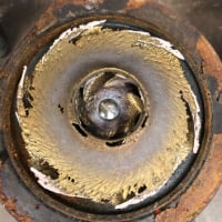
Thanks @EBEBRATT-Ed . Knowing this sound only presents when the water is heated, what would be any obvious items/tell-tale signs to notice if I take a look at the circ assembly? When a wet rotor is failing, is it all or nothing? Are there items that may expand when heated that could cause this issue?
In lieu of not draining the system, the only spot I could possibly pipe in a gauge would be within the MU piping (taking advantage of the service valves).
Thank you!0 -
Hi, What is the piping material? If steel, you could drill and tap for a 1/8" gauge. 🤠
Yours, Larry
1 -
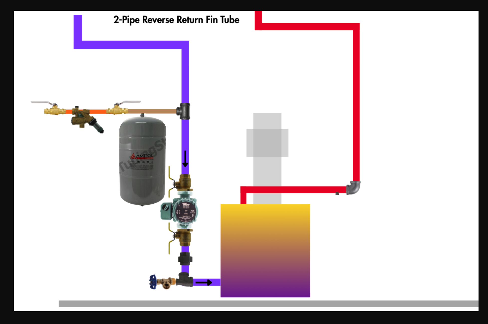
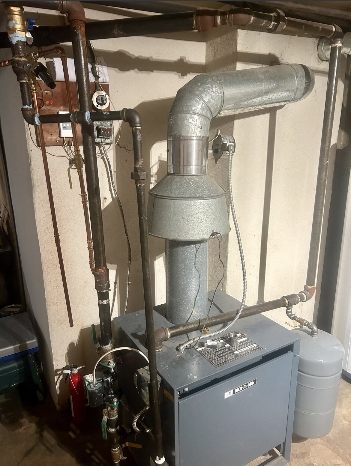
Attach a pic of the boiler and piping, it may be fairly easy to move the exp tank to the circ inlet. That may solve a few issues for you.
Bob "hot rod" Rohr
trainer for Caleffi NA
Living the hydronic dream1 -
this was before the circ swap to the 0010.
Much less purging issues and no-heat calls since I replaced the 0015 ecm circ.
 0
0 -
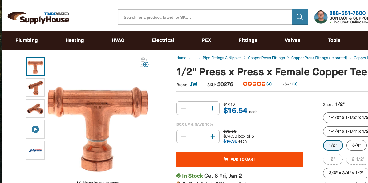
If the green pump is flowing down into the boiler? Your expansion tank re-position is super simple. This 1/2 copper fill valve line is where you tee in. A quick easy job for someone with a press tool.
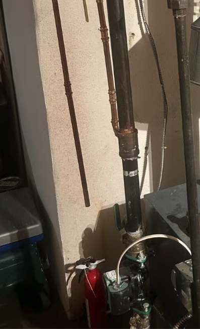
Add a tank service valve while you are at it.
\
 Bob "hot rod" Rohr
trainer for Caleffi NA
Living the hydronic dream1


Categories
- All Categories
- 87.6K THE MAIN WALL
- 3.3K A-C, Heat Pumps & Refrigeration
- 59 Biomass
- 429 Carbon Monoxide Awareness
- 124 Chimneys & Flues
- 2.2K Domestic Hot Water
- 5.9K Gas Heating
- 119 Geothermal
- 168 Indoor-Air Quality
- 3.8K Oil Heating
- 78 Pipe Deterioration
- 1K Plumbing
- 6.6K Radiant Heating
- 394 Solar
- 15.9K Strictly Steam
- 3.5K Thermostats and Controls
- 56 Water Quality
- 50 Industry Classes
- 50 Job Opportunities
- 18 Recall Announcements