Heat Pump Cooling Not Working

First time trying to switch on the cooling in my house since we move in. The house contains 2 thermostats controlling two outdoor HVAC Units for different rooms. (Heating for the house is using boiler)
Thermostat A works fine to turn on the cooling (when cooling on is set, outdoor unit starts fine), but the Thermostat B doesn't seem to do anything (outdoor unit won't turn on).
I check the wiring found those two are using completely different wiring.
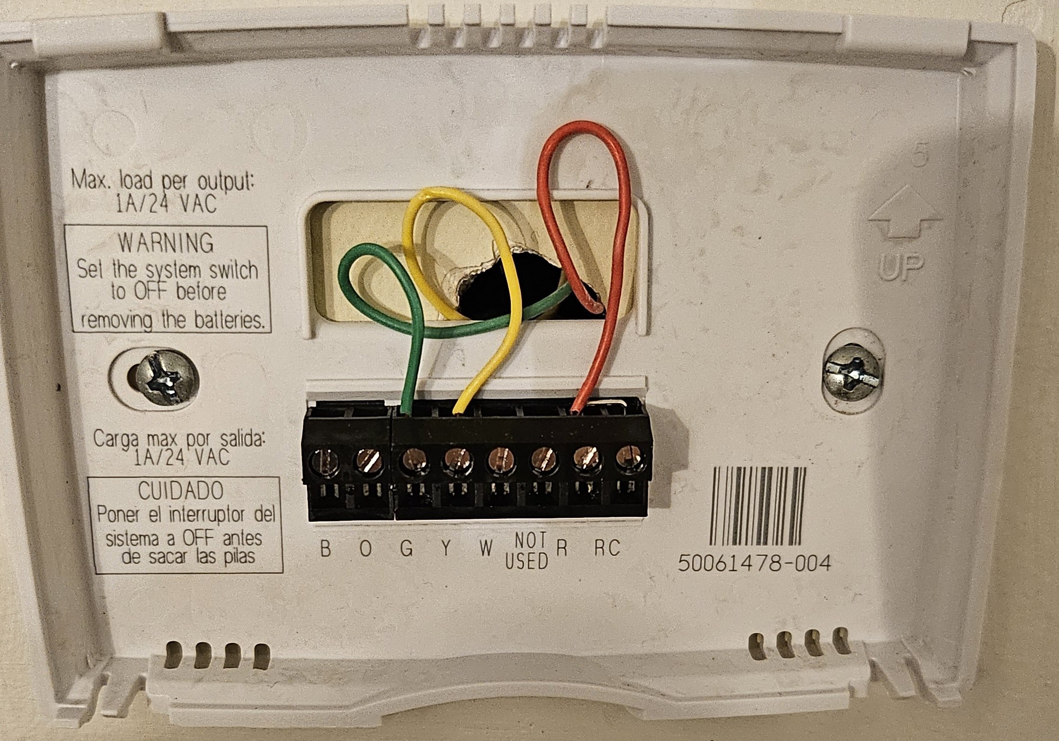
Thermostat A (working) is using 3 wires G Y R
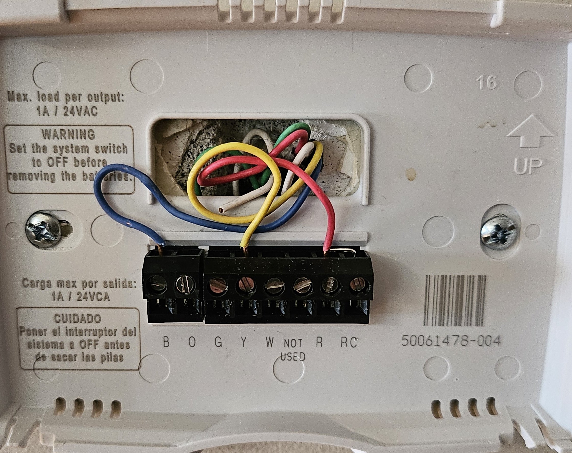
Thermostat B (not working) is using 3 wires B Y R
Anyone know based on the wiring, is Thermostat B wired for cooling or not? Thank you
Comments
-
Thermostat B serves a heat pump. It does air conditioning, and heat (AC in reverse). Indoor blower motor (fan) is on but the outdoor unit isn't? It could be any number of things. Low refrigerant pressure. High refrigerant pressure. Contactor. Capacitor. Relay. Defrost board. Compressor. Where are you located? It needs an HVAC tech who knows heat pumps.
0 -
Both indoor fan and outdoor unit are not on.
1 -
jumper r to y and see what happens
 1
1 -
Switch off. Circuit breaker off or tripped for the air handler. Fuse in the air handler.
If the breaker is tripped or the fuse is blown in the air handler, it happened for a reason.
A heat pump air handler might have breakers in the air handler door if there's electric resistance heaters.
0 -
Just measure the voltage on Thermostat B wires, there is no AC voltage between any of the two wires.
Checked electric panel all the switches are on.
0 -
Blown fuse or transformer. But why?
0 -
You probably won't read any voltage at the stat that will make sense. The stat is a switch so you only have HOT 24 volts to it on the red R wire . You don't have the other leg of the 24 volts there.
If you jump R & Y with the stat off the wall the indoor fan in the AHU should start and the outdoor unit should start.
If it doesn't go to the Air handler and find the control circuit transformer. it should have 120 or 240 feeding the transformer (see Ahu name plate) and then 24 volts coming out of the transformer.
Make sure the breaker to the trans is on and any 24 volt fuse in the ahu is good.
0 -
You need to look at the other end of the B tstat cable at the air handler.
If that blue is connected to the common, it could be a problem.
 1
1 -
You'll read 24 volts across R and Y when testing at the thermostat sub base if the system is powered and the transformer and fuse is good. Y will read as Common coming through the contactor coil.
1 -
~24vac
0 -
First time trying to switch on the cooling in my house since we move in. The house contains 2 thermostats controlling two outdoor HVAC Units for different rooms. (Heating for the house is using boiler)
That being said I would think that the unit is straight A.C. If that is the case, someone hooked the blue wire up to the B terminal thinking that was a common? Remove the blue wire from the subbase and jump R and Y Indoor fan should start as well as the outdoor fan and compressor. Don't be impatient there could be a built in delay in the out door unit.
0 -
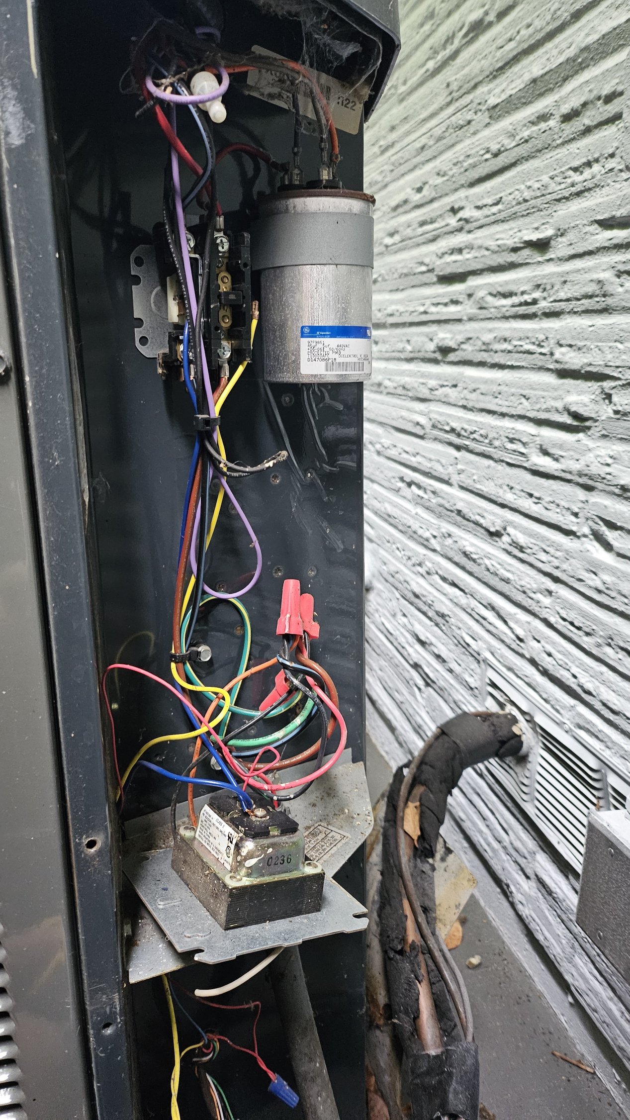
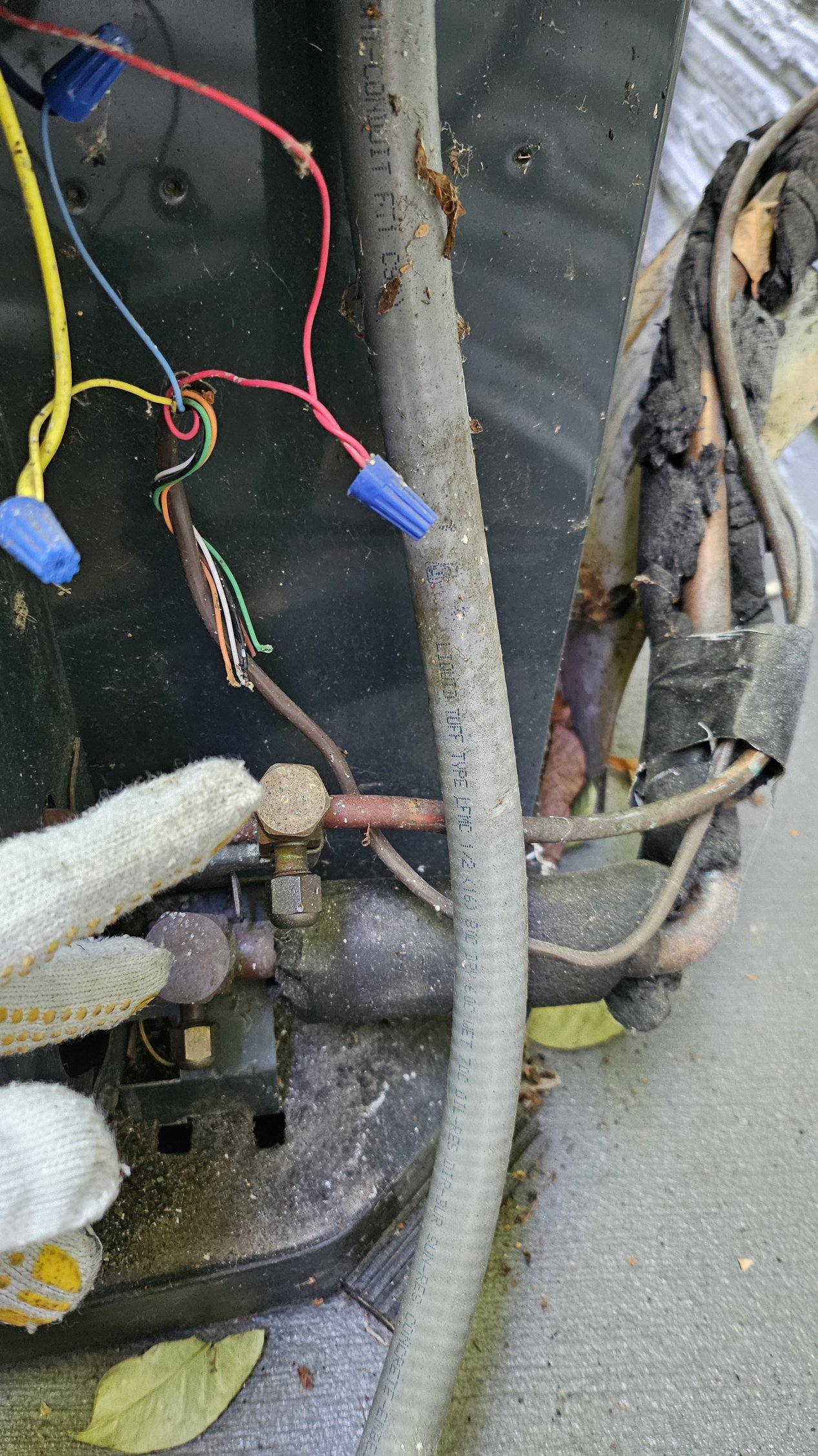
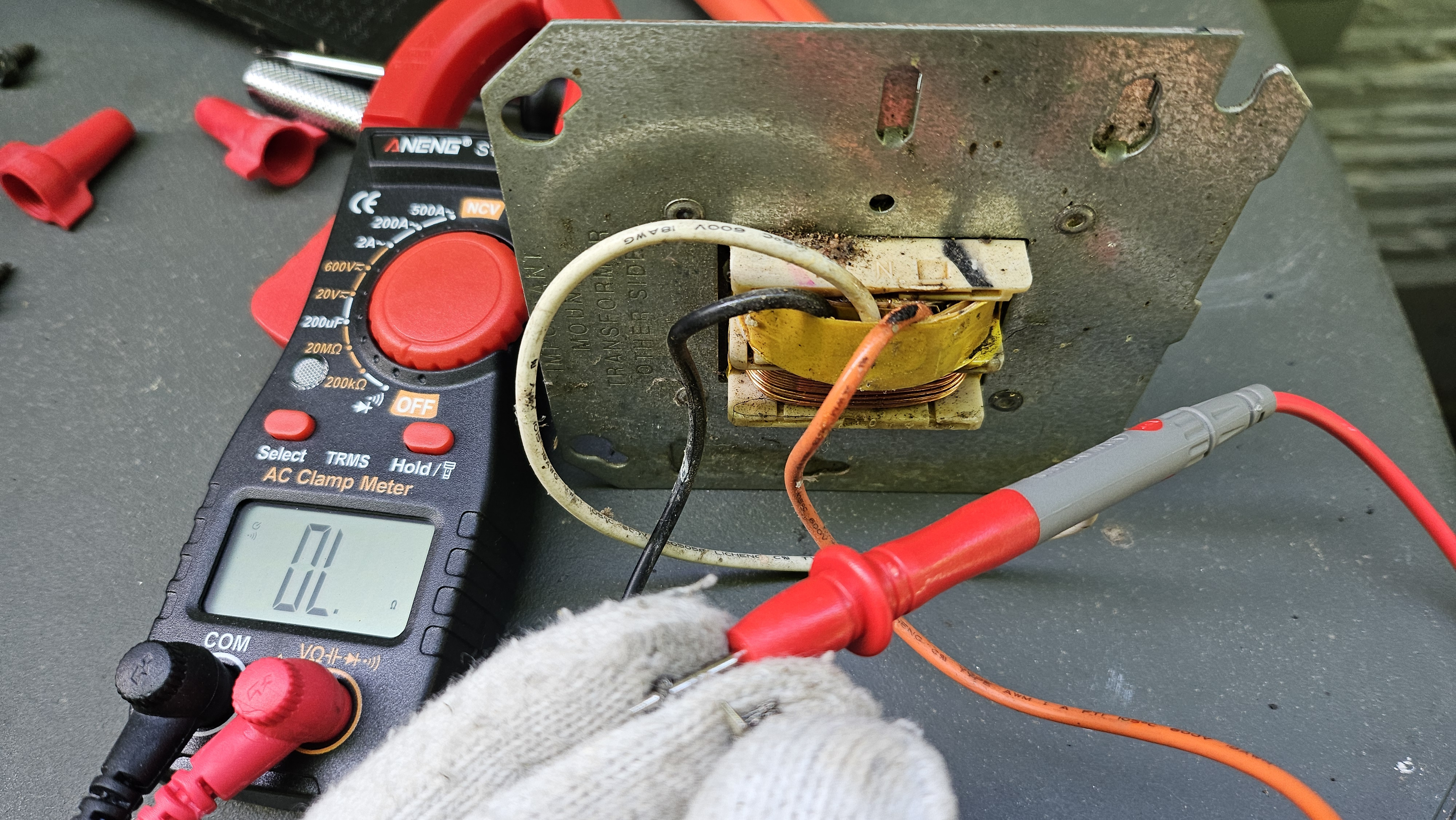
I finally got a chance to trace the wiring and all three wires go directly to the heat pump.
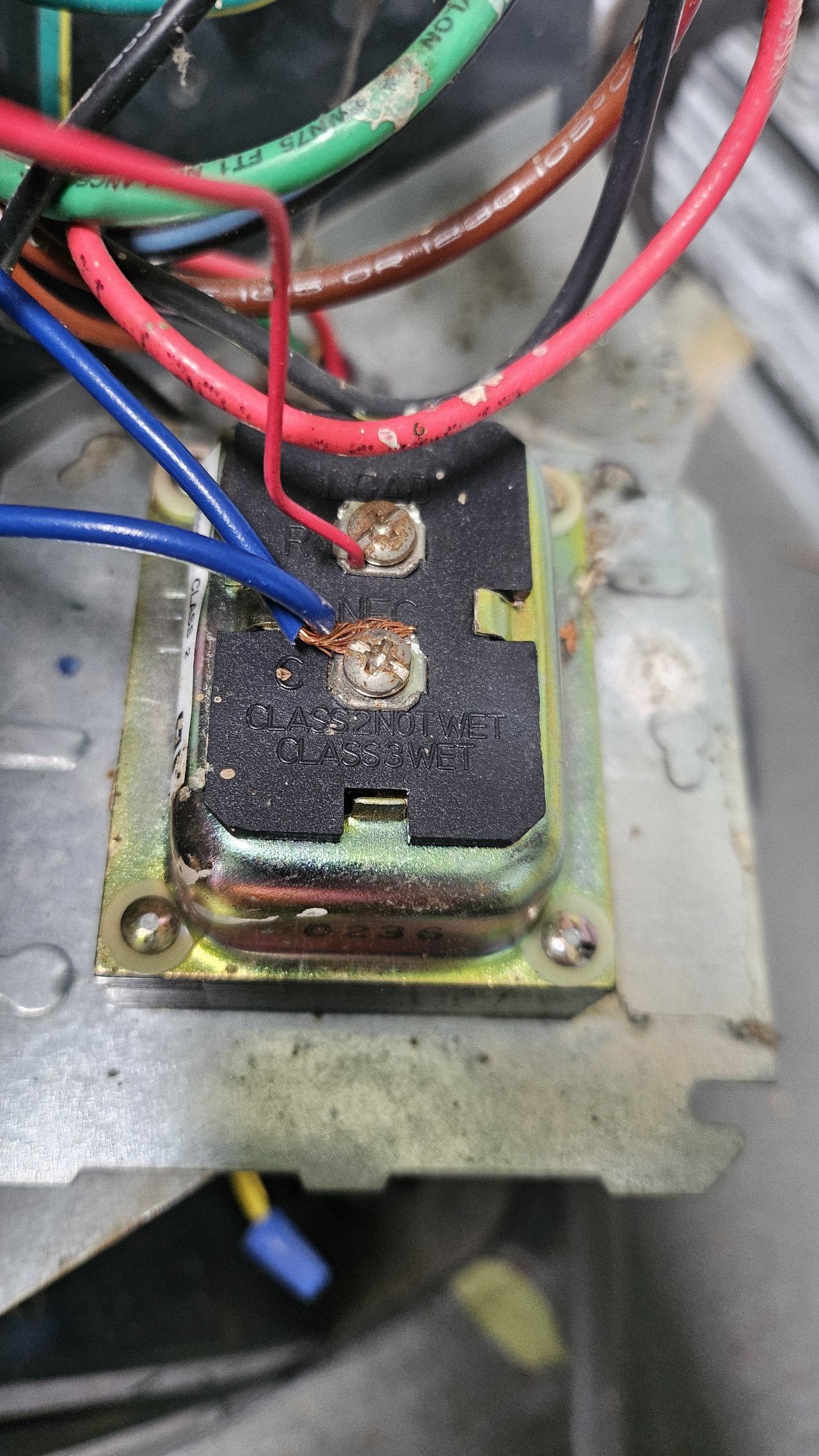
Red and blue goes to R and C of this transformer and the yellow wire goes to this relay.
Is this transformer fried? I measure the resistance between r c it shows almost 0 ohm.
 0
0 -
When you measured " Is this transformer fried? I measure the resistance between r c it shows almost 0 Ohm. "
Was the power to the outdoor unit turned off ?
Was at least the 2 Blue wires and/or the Red wire disconnected from the transformer's secondary winding ?
Was the meter set to the lowest Ohms range ?
Does it smell fried ?
0 ohms seems a bit low I would expect maybe between 0.5 to 10.0 Ohms. In this case you have to know your test equipment, its capability and the ability to use it correctly. Wrong information from a test may lead you in the wrong diagnostic direction.
If the output (Secondary winding) of the transformer is internally shorted or overloaded it would probably would burn out the primary, so the primary would be an open circuit (1000s of Ohms up to infinite Ohms in this case).
Sadly with transformers and other electrical / electronic components Ohmmeter measurements can be confusing unless you have a known good to compare to. Ohmmeter tests are safer since the meter is supplying the power.
The first test I probably would have done with minimal system disassembly and the system primary power (I suspect 240 VAC) switched on for the test, is measure the transformer's secondary voltage, should be 24 VAC or a bit higher. If the primary power has been on all this time was the transformer slightly warm and humming ? To be cautious, with the primary power turned off, the metering could be set up then the power turned on to make the measurement.
Measuring for the presents of the actual working voltages often gives better diagnostic direction. However when measuring higher voltages more care, skill and knowledge, is needed to be safe and not damage yourself, the equipment under test and/or the test equipment.
Tests and measurements should be diagnostic in nature and provide good diagnostic direction.
A 'Divide and Conquer' Example;
No 24 VAC, is the transformer bad or no power to the outdoor unit, 240 VAC wiring issue ?
24 VAC good, relay coil defective (open) or the thermostat is defective or thermostat wiring has been compromised somewhere.
You want more good answers and less unknowns and questions. The correct diagnostic tests gets you looking in the correct direction quickly.
Another simple test is connect the R and Y thermostat wire together at the outdoor unit, does it start when the power is applied ?
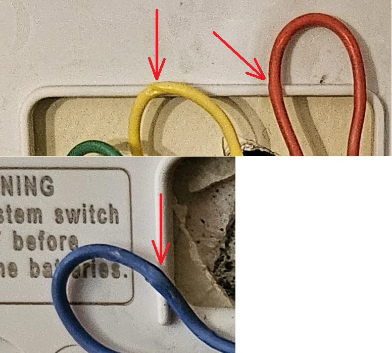
Also kind of also wondering if that Blue wire is connected at the thermostat correctly. It looks like it may have the functionality of a C wire at the outdoor unit but the thermostat base has no C connection. Maybe it is repurposed at the indoor unit or maybe actually not needed.
National - U.S. Gas Boiler 45+ Years Old
Steam 300 SQ. FT. - EDR 347
One Pipe System0 -
In general crushing the wires is not a good thing.
 National - U.S. Gas Boiler 45+ Years Old
Steam 300 SQ. FT. - EDR 347
One Pipe System1 -
Why is the transformer in the outdoor unit? Its not from 1982.
0 -
When I disassemble and measure I turned off the outdoor pullout disconnect switch to avoid getting electric shock.
I have tried connected R Y directly at thermostat B terminal nothing happened.
I am going to measure the R C voltage at transformer output later today and report back. I am suspecting it's not outputting any voltage.
0 -
Is there also a transformer in the air handler?
0 -
For thermo B, I don't see any of the wire goes to air handler. 3 wires go directly to outdoor unit and those two metal pipes goes from outdoor unit to air handler.
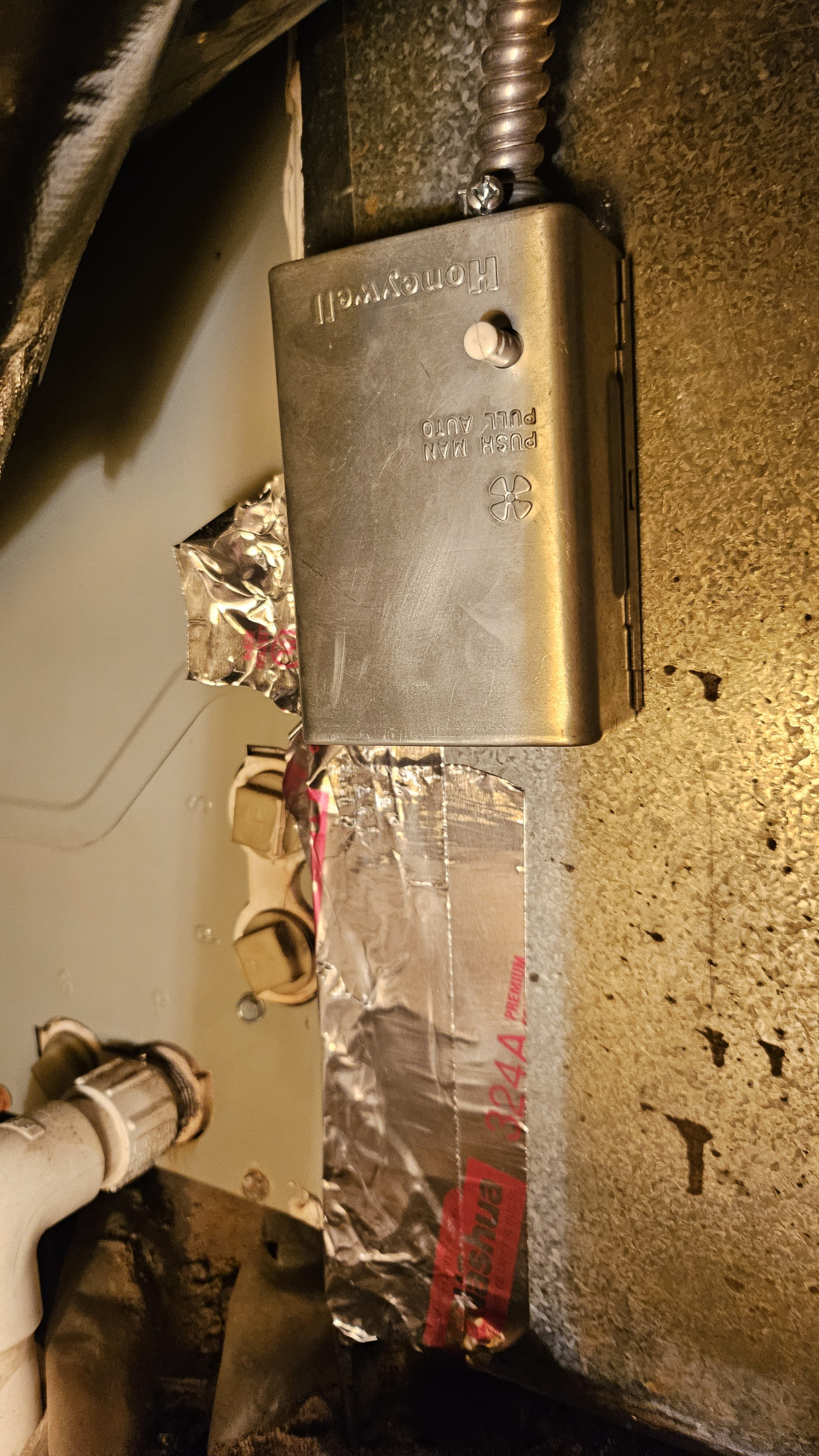
The AH for this one is hard to reach under crawlspace, I see there is a Honeywell temperature switch on the side of the AH a similar temperature switch from my boiler AH. I couldn't find any transformer in AH.
 0
0 -
Follow up on the measurement. The 240V successfully enters outdoor unit, but the transformer output 0V. I disconnected the transformer and measured an open circuit between black and orange. Seems confirming transformer is broken?
The transformer unit is Honeywell AT140D1046 (120/240V to 24V). I see that this model is out of date, maybe can use Honeywell AT140A1042 as an replacement?
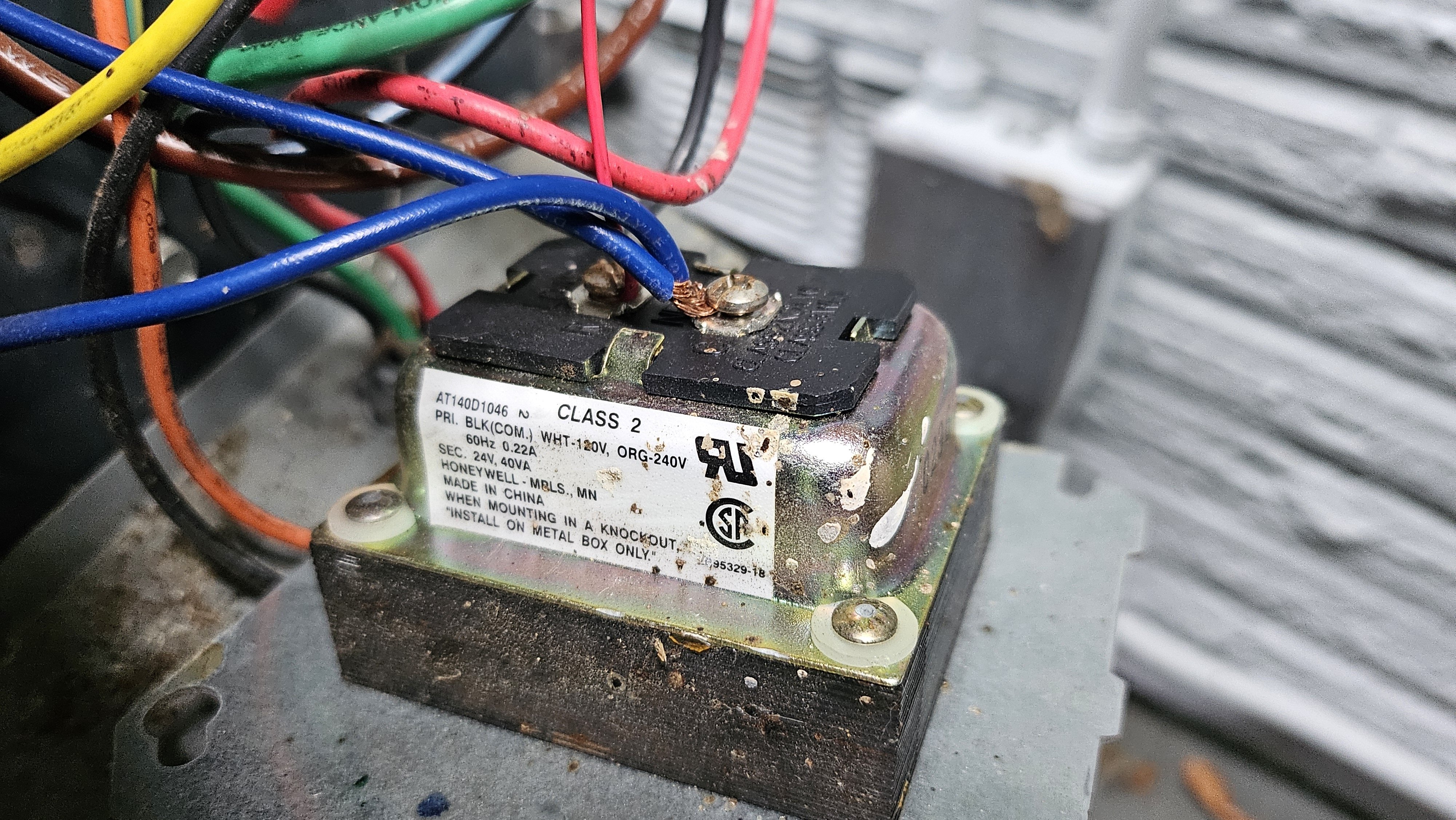
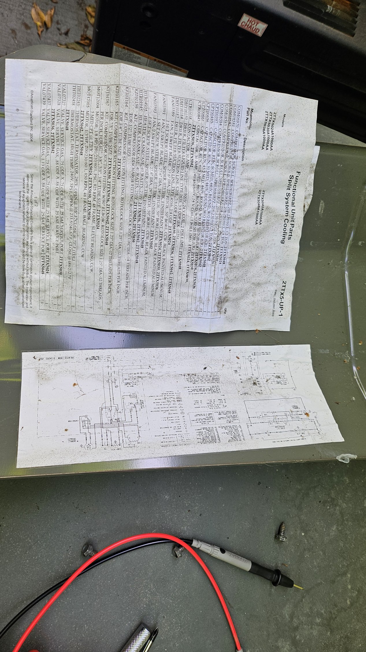
Also found the unit part sheet seems this unit dated back from 2004.
 0
0 -
I just trying to understand the existing wiring here.
B (blue wire) goes to transformer C
R (red) goes to transformer R
Y (yellow) goes to relay
When thermostat is set to "cooling on", B R Y will be connected together. Then the trasformer RC will be connected and create a short on transformer secondary terminal? Doesn't seems right.
The AC unit was installed in 2004. The thermostat is a 2019 model and the manual says no need to connect common wire. Maybe the prior owner somehow change thermostat and thought C wire is B wire and fried the transformer?
0 -
With what you are finding with the current state of dysfunction, your speculation that the 2019 model thermostat was connected wrong makes sense. I would disconnect the blue wires at each end of the thermostat cable and also that short piece of blue wire that goes between to the original transformer and the blue wire in the thermostat cable.
It seems all you need is the R on the transformer to the R on the thermostat, during an AC call the thermostat closes RC to Y (note jumper between R and RC), Y goes to the coil of the contractor and the other Blue wire connects the other side of the contractor's coil to the C of the transformer.
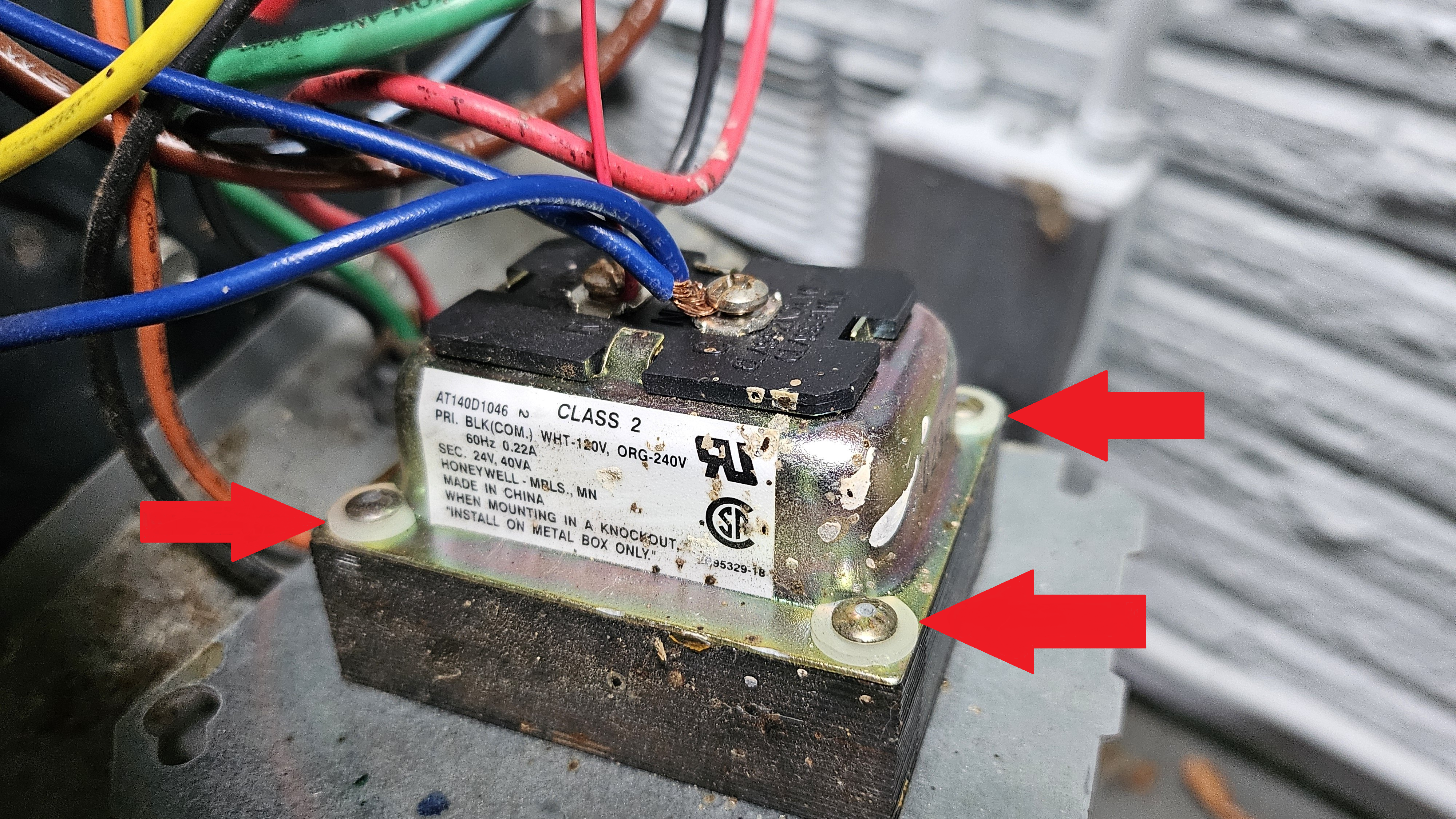
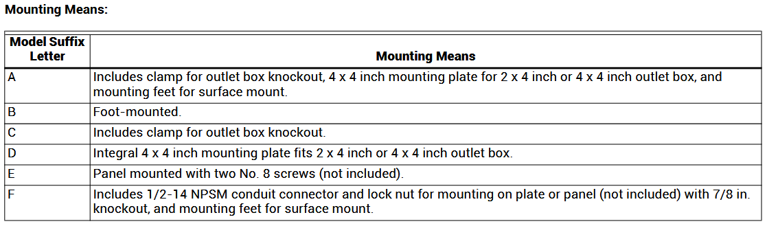
Not sure what the difference is with the original AT140D1046 and the Amazon AT140A1042 except the original comes with the junction box mounting plate which is secured with insulated rivets at one end, and the Amazon seems to be just the transformer with insulated rivets. If you do a transformer transplant using the original cover plate the insulated washers must stay intact.
There seems to be some oddities about that original transformer, char marks and maybe an arc flash event in the near vicinity. The secondary winding does not look overheated. If the thermostat shorted the secondary like you speculate the primary may have quickly become an open circuit like you are finding.
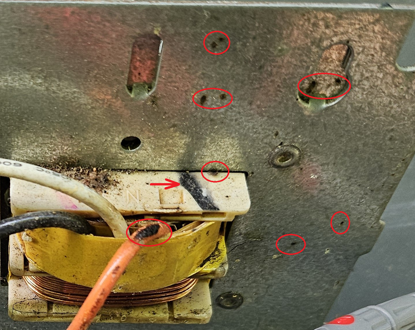
With a new transformer you could add a 3 Amp fuse on one side of the secondary winding to protect the transformer in case other issues still exist.
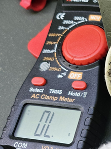
Curious, does that meter have any other Ohmmeter ranges besides 200K and 20M ? That meter may have very poor resolution when looking at resistances under 10 Ohms. You would have to check the user manual.
 National - U.S. Gas Boiler 45+ Years Old
Steam 300 SQ. FT. - EDR 347
One Pipe System1 -
https://customer.resideo.com/resources/Techlit/TechLitDocuments/68-0000s/68-0054.pdf
National - U.S. Gas Boiler 45+ Years Old
Steam 300 SQ. FT. - EDR 347
One Pipe System0 -
@heatingrabbit, this is a Fan/Limit control.
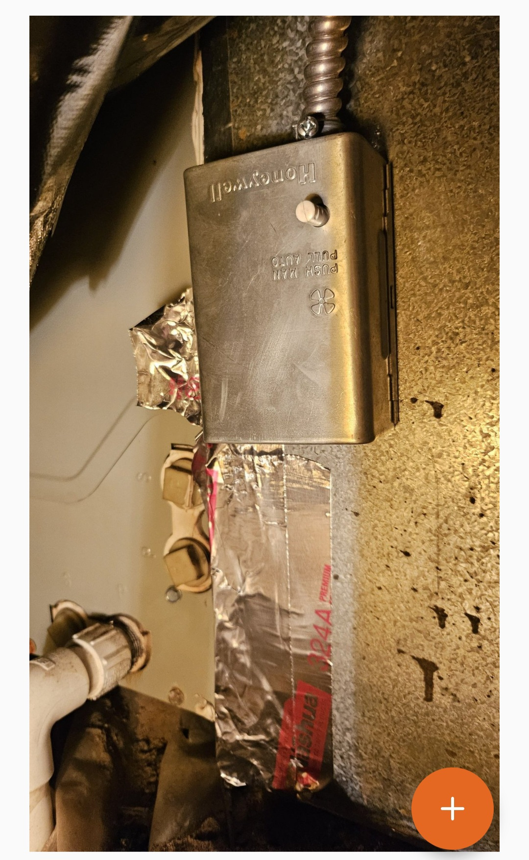
Its part of the heating portion of the system, not the AC. There's some type of horizontal furnace there. I assume thats why there's 2 thermostats.
There should be a transformer in the furnace. Probably 40 va, and enough for both. With the AC transformer in the condenser, it tells me someone's hands have been touching things they shouldn't be touching. Transformers haven't been in condensers since they used belt drive motors. So Ohm out the wires, take notes, pictures, label the wires, and add a 3 amp fuse to the new transformer.
1 -
I usually use Continuity Test mode to measure ohm of lower resistance part of the circuit (that's what I am using in the picture).
I ordered that transformer from Amazon arriving today. Will report back if the unit fires up after the fix.
0 -
After replacing the transformer, now connecting R Y the unit can starts properly. Removed the B wire from thermostat B panel and the thermostat controls on and off properly.
Now found the next issue: the unit is not cooling. Checking the outdoor unit while running, the fan is blowing regular temperature air and the copper pipe is not cold. (Comparing with the working unit, thefan should be blowing hot air and thick copper pipe should be cold)
The sympton seems indicating the condensor not working properly?
0 -
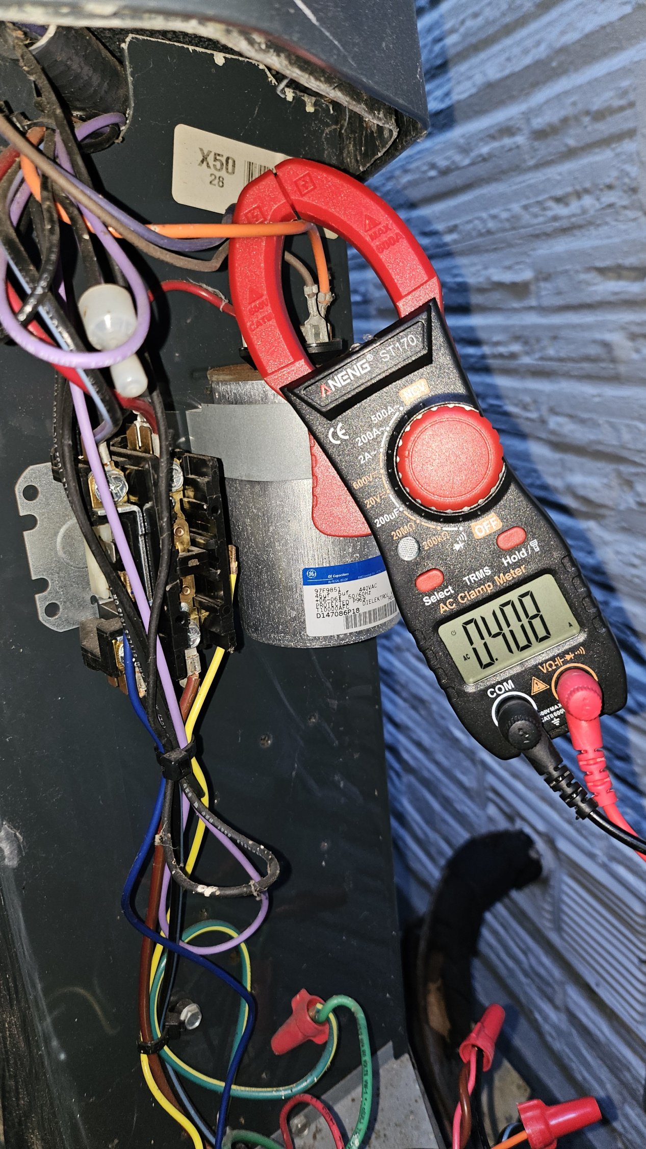
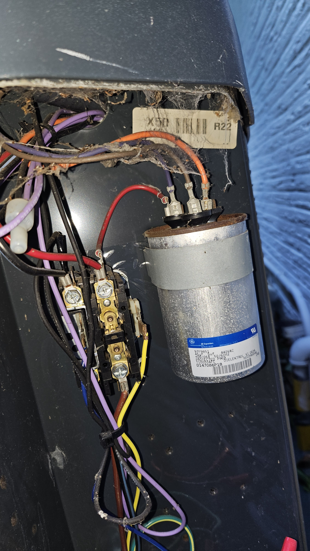
Checking the running current. Overall only 0.9A. Seems quite low. Suspecting compressor not working.
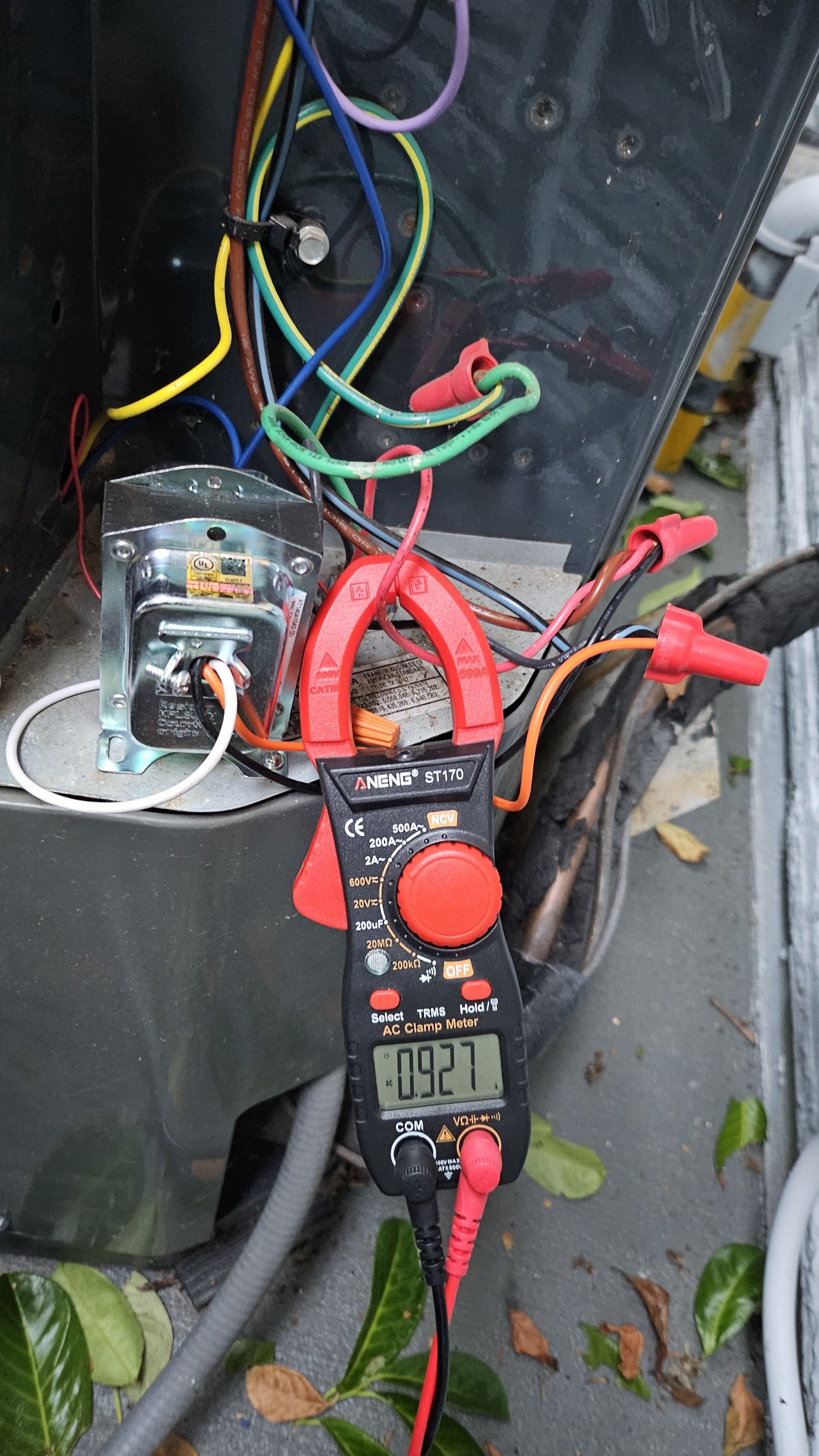
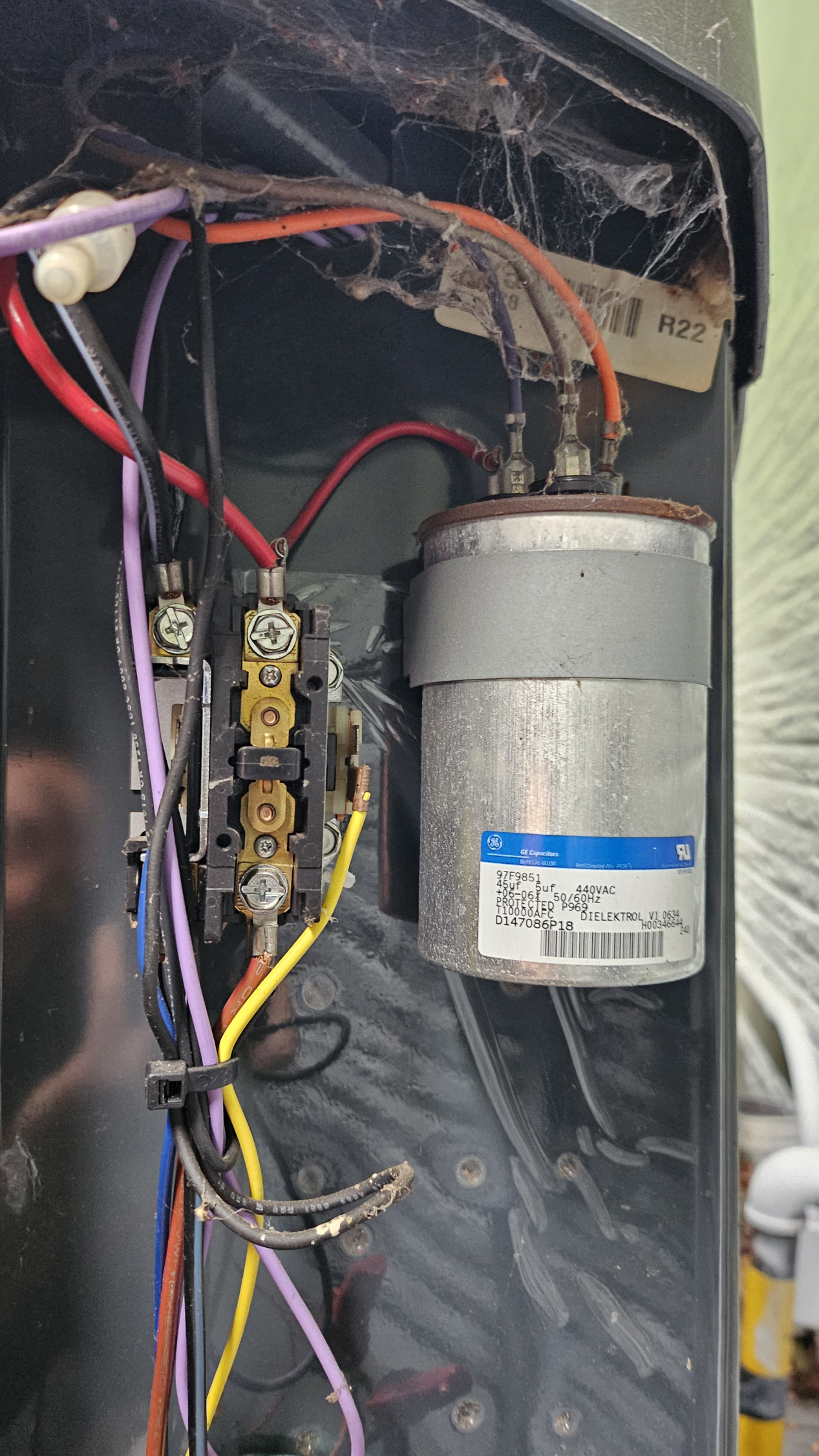
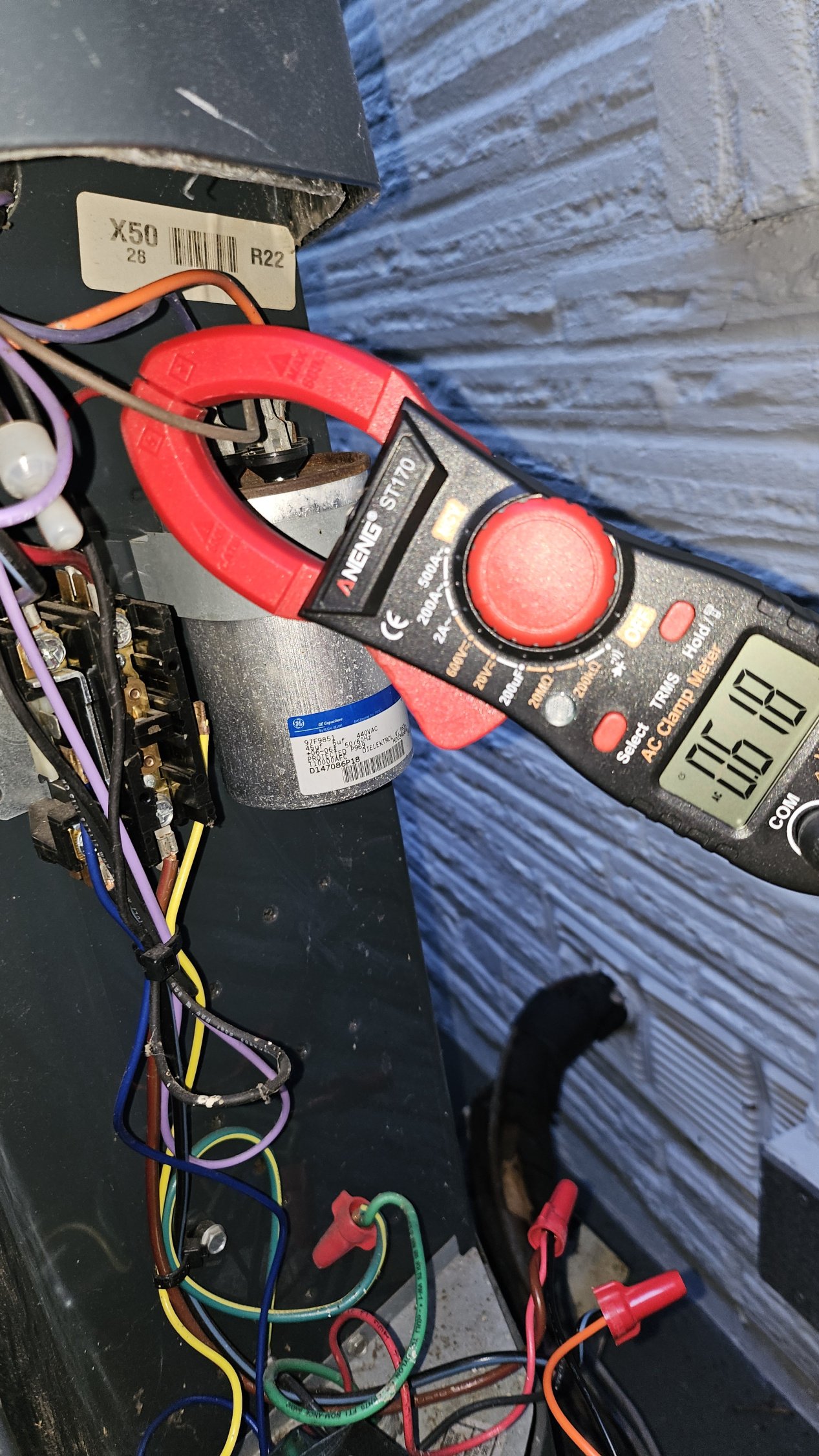
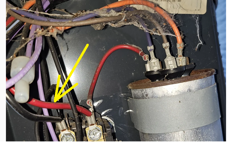
Checking the fan and compressor line on the capacitor. Compressor (Orange line?) is only using 0.4A too low. Suspecting the capacitor is broken.
 0
0 -
Along with the condenser fan the compressor has to be running too. If the compressor is running the refrigerant charge may be too low.
National - U.S. Gas Boiler 45+ Years Old
Steam 300 SQ. FT. - EDR 347
One Pipe System0 -
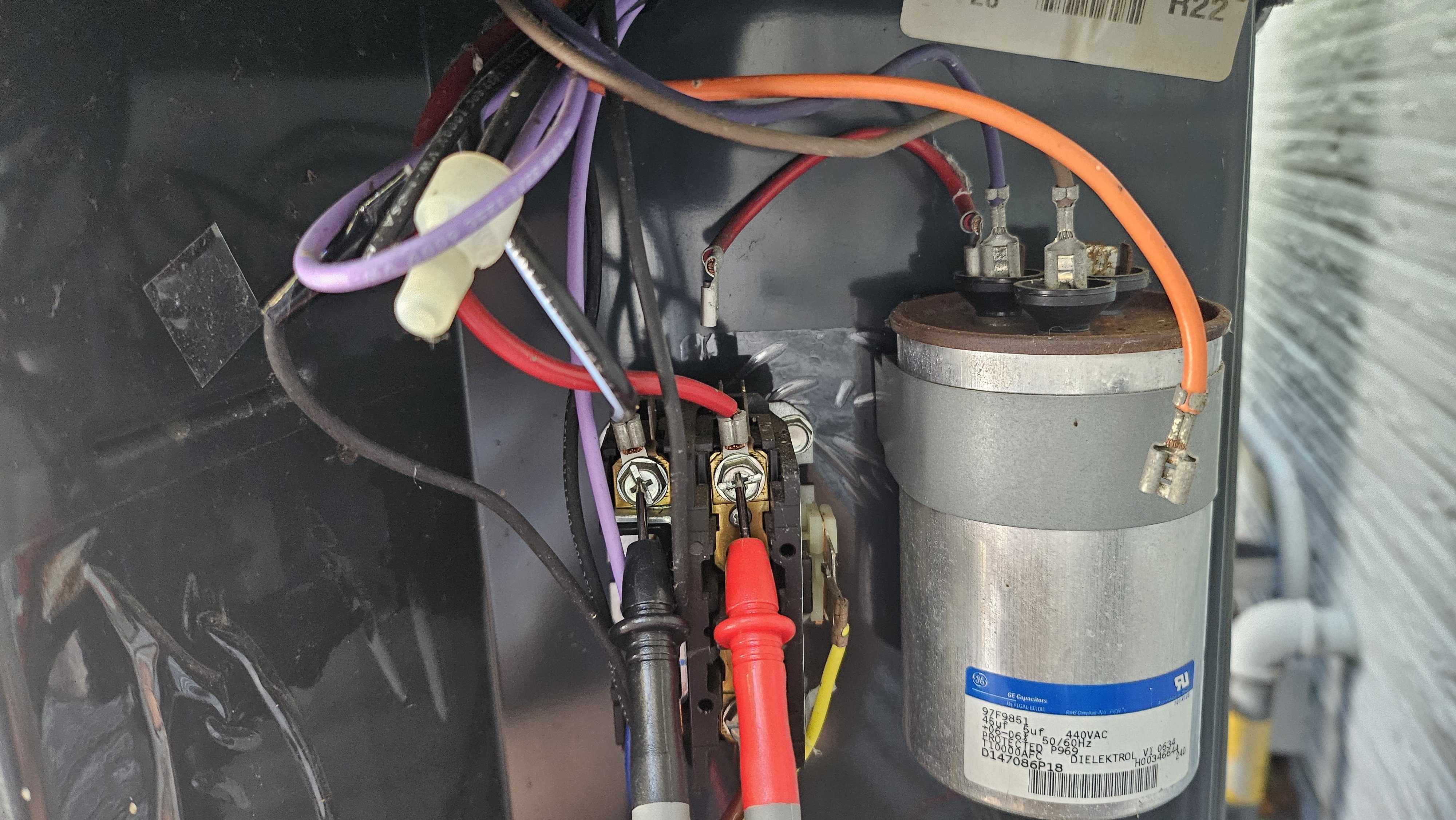
I am suspecting the compressor is not running given the low current on that wire.
I tested that 45 + 5 uf capacitor a bit. It's showing 4.9 uf between fan and Com terminal and 41.3 uf between compressor and com terminal. I also comparing the working AC unit capacitor showing exactly 5 uf on fan terminal and 45 uf on compressor terminal.
41.3 vs 45 is this a big difference that could have caused the compressor not starting up?
0 -
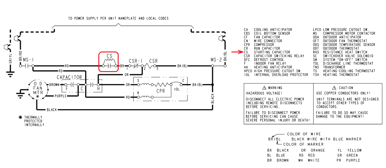
is the compressor start up circuit working ?
 National - U.S. Gas Boiler 45+ Years Old
Steam 300 SQ. FT. - EDR 347
One Pipe System0 -
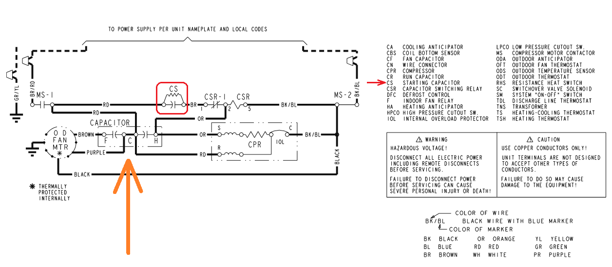
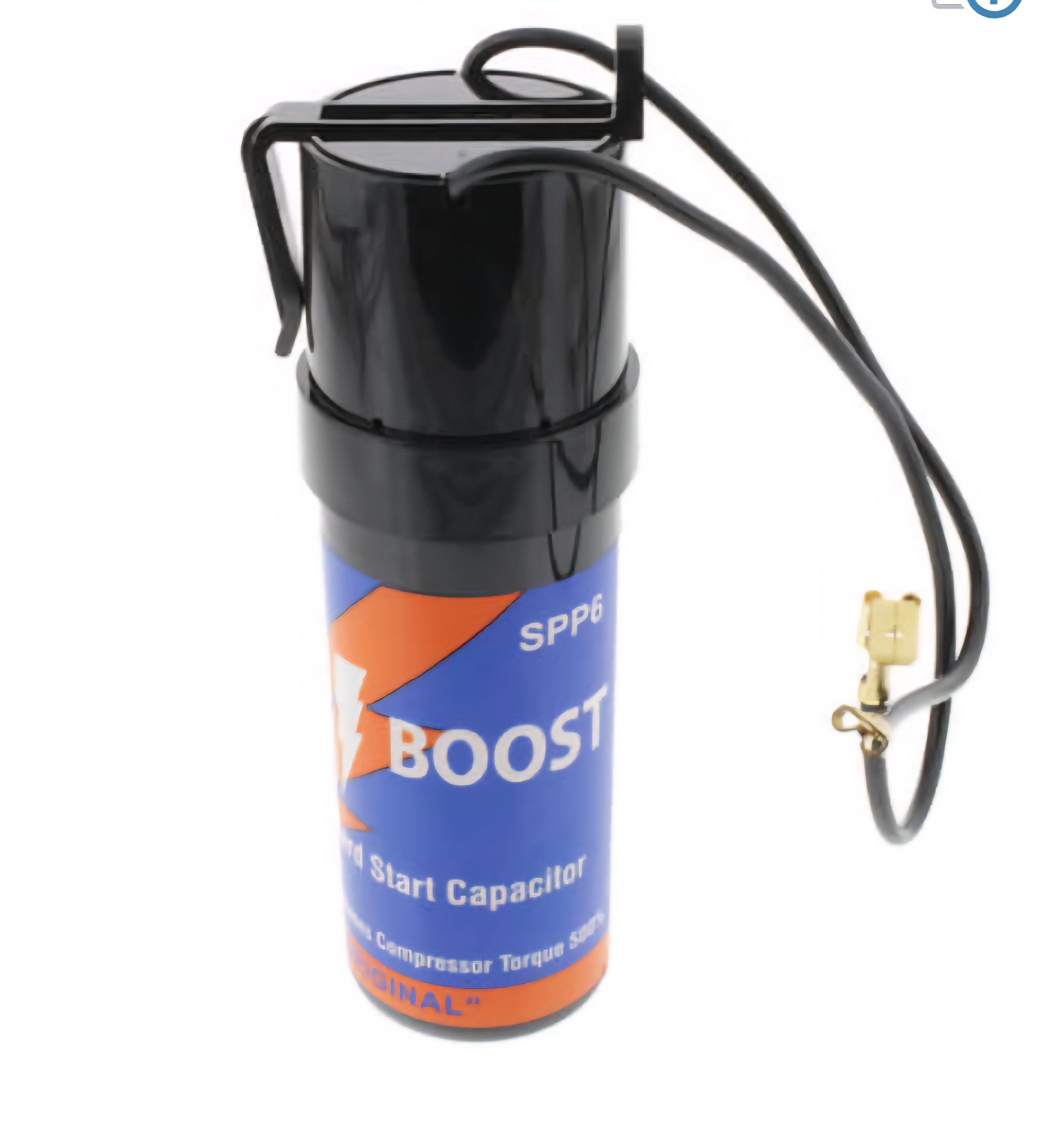
Is this the starting capacitor you are referring to in your diagram? I measure the capacity it's a bit of 41.3 uf (measured value) vs 45 uf (expected value). Other that the capacity difference how can I know if the start up circuit is working or not?
 0
0 -
It looks like the 45uF part Capacitor is out of spec. +/- 6% However at 41.3 uF I would think it still would work.
 National - U.S. Gas Boiler 45+ Years Old
Steam 300 SQ. FT. - EDR 347
One Pipe System1 -
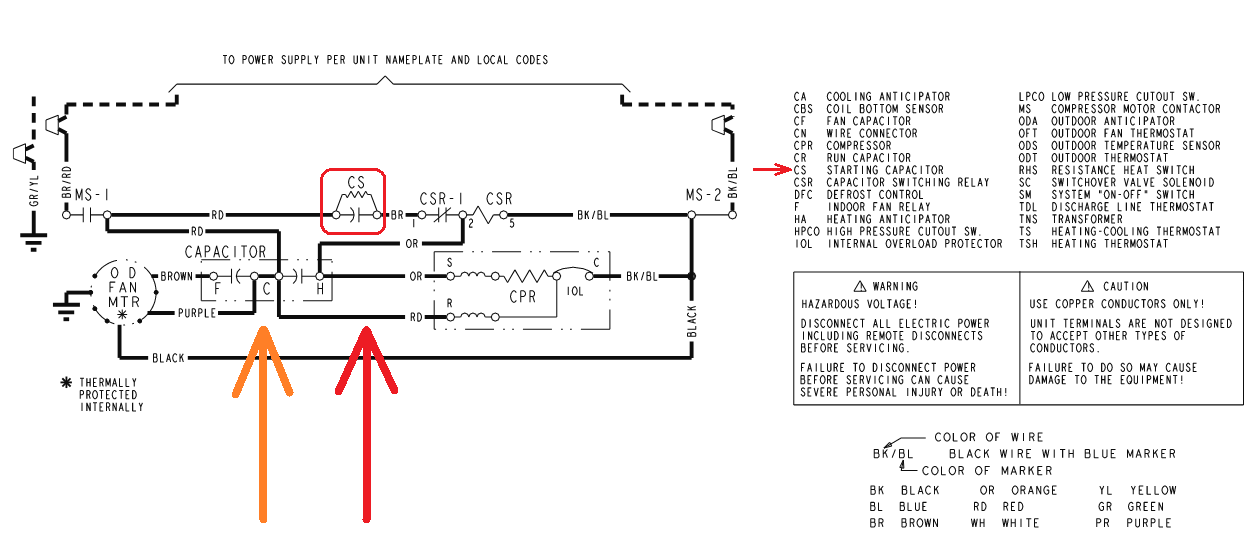
I believe the Capacitor you are measuring at is the one at the Orange arrow in the diagram.
 National - U.S. Gas Boiler 45+ Years Old
Steam 300 SQ. FT. - EDR 347
One Pipe System0 -
In the side panel of the ourdoor unit I don't see any starting capacitor. Where is this starting circuit usually located? Do I need to further disassemble the unit?
0 -
Is the Red wire missing (Red arrow) ? I count 3 wires on the C terminal of that Capacitor 2 Red and one Purple. It may be wired differently, the Red going to CS may also go to the R terminal on the compressor. It may be just they way they drew the diagram. Is there continuity through the compressor windings ?
 National - U.S. Gas Boiler 45+ Years Old
Steam 300 SQ. FT. - EDR 347
One Pipe System0 -
I would think it would be in the compartment you are in.
I would look at the other end of the Red wire.
 National - U.S. Gas Boiler 45+ Years Old
Steam 300 SQ. FT. - EDR 347
One Pipe System1 -
Start capacitor and relay are an option. Yours doesn't seem to have it.
Remove the start, run, and common leads from the contactor and capacitor for the compressor. Check continuity across all 3 compressor leads. There should be measurable resistance across all 3. Then check each compressor lead to ground. If any lead is grounded, the compressor is done. And the refrigerant is now acidic from the burned out compressor byproducts.
I see a "Hold" button on your meter. Does it capture readings? Are you able to test amp draw at startup? The compressor should at least try to start. If its drawing locked rotor amps (LRA on the ratings tag), or the windings are opening on thermal overload, you could try a Hard Start Capacitor/Relay Kit.
 1
1 -
Also check you refrigerant charge. If it's low enough the compressor shouldn't start.
Br. Jamie, osb
Building superintendent/caretaker, 7200 sq. ft. historic house museum with dependencies in New England0 -
IF there were pressure controls, that would certainly be the case. However, the contactor has 24 volts and the condenser fan motor is running, so the circuit is complete.
0 -
not all units have safety’s.
0 -
I try to measure resistance between S R C for the compressor.
From diagram I am assuming Black/Blue wire goes to compressor Common, Red - Run, Orange - Start
C - R 1.4 ohm
C - S 2.3 ohm
R - S 3.5 ohm
I disconnect orange and measured the wire on contactor (should be fine?)
I also measure those three wire against ground wire no conductivity.
Does the measurement indicate the compressor is fine?
 0
0


Categories
- All Categories
- 87.7K THE MAIN WALL
- 3.3K A-C, Heat Pumps & Refrigeration
- 59 Biomass
- 430 Carbon Monoxide Awareness
- 129 Chimneys & Flues
- 2.2K Domestic Hot Water
- 5.9K Gas Heating
- 122 Geothermal
- 170 Indoor-Air Quality
- 3.8K Oil Heating
- 79 Pipe Deterioration
- 1.1K Plumbing
- 6.6K Radiant Heating
- 396 Solar
- 16K Strictly Steam
- 3.5K Thermostats and Controls
- 56 Water Quality
- 51 Industry Classes
- 51 Job Opportunities
- 17 Recall Announcements