Help with wiring ECOBEE thermostat with 18/3

We have a gas-fired Weil-McLain EG55PIDN series 4, 2001 model in good working order, and serviced annually. Two pipe system with 19 radiators, all in good working order with fresh traps and valves.
We would like to upgrade our thermostat to an Ecobee Smart Enhanced model with Wi-Fi capability, so that we can monitor temperatures and turn the boiler on/off remotely.
The existing thermostat is connected via 18/2, using a red and white ran a new 18/3 wire.
There's a 24 V transformer as shown in the photo below below, with the following terminals:
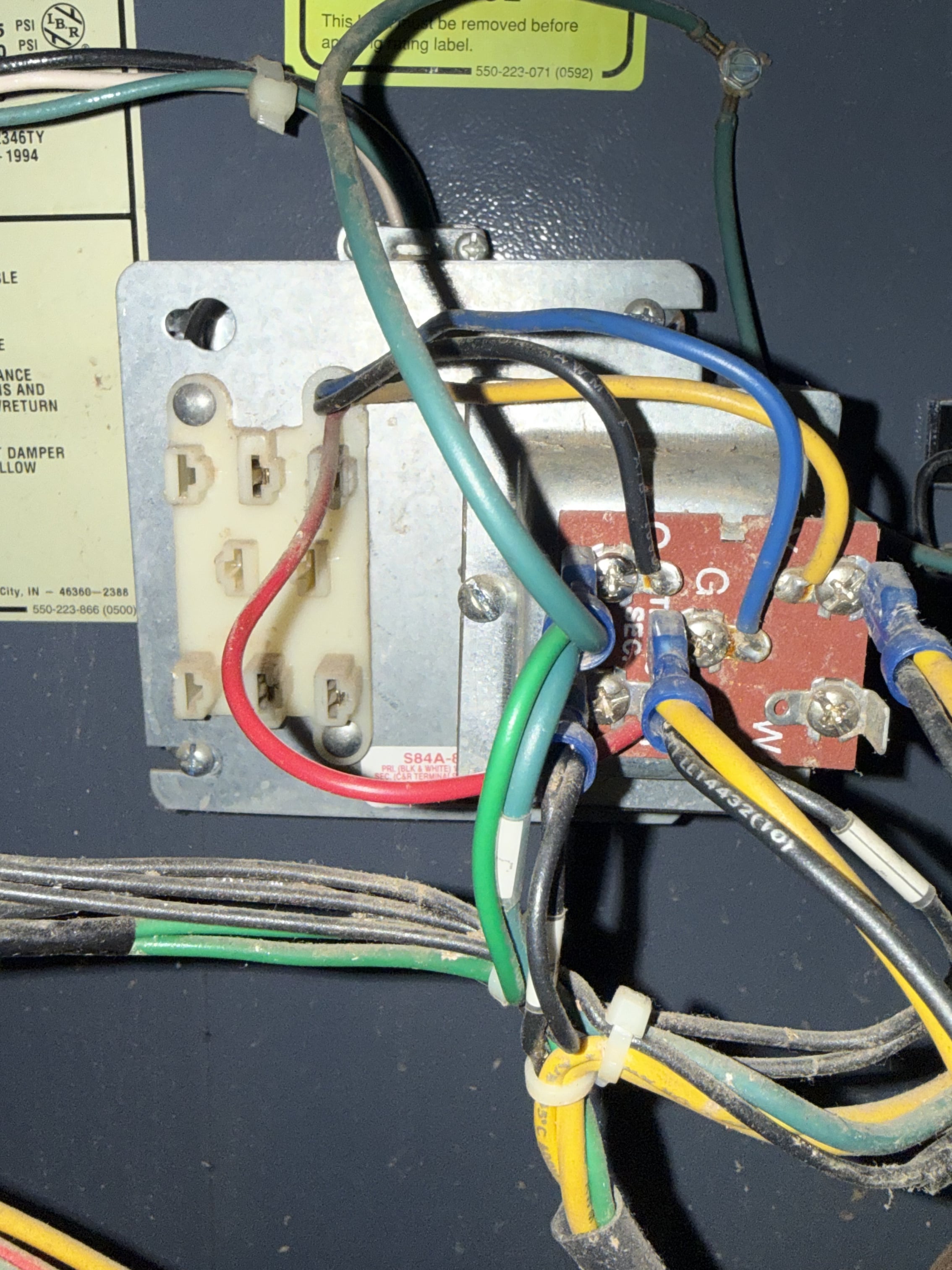
Y - connected to the white thermostat wire
G - connected to the red thermostat wire
C
W
Trans Sec
There's also a Honeywell SB8610U ICM continuous retrywith several of terminals. There's also water feeder and an LWCO, which I certainly don't want to bypass.
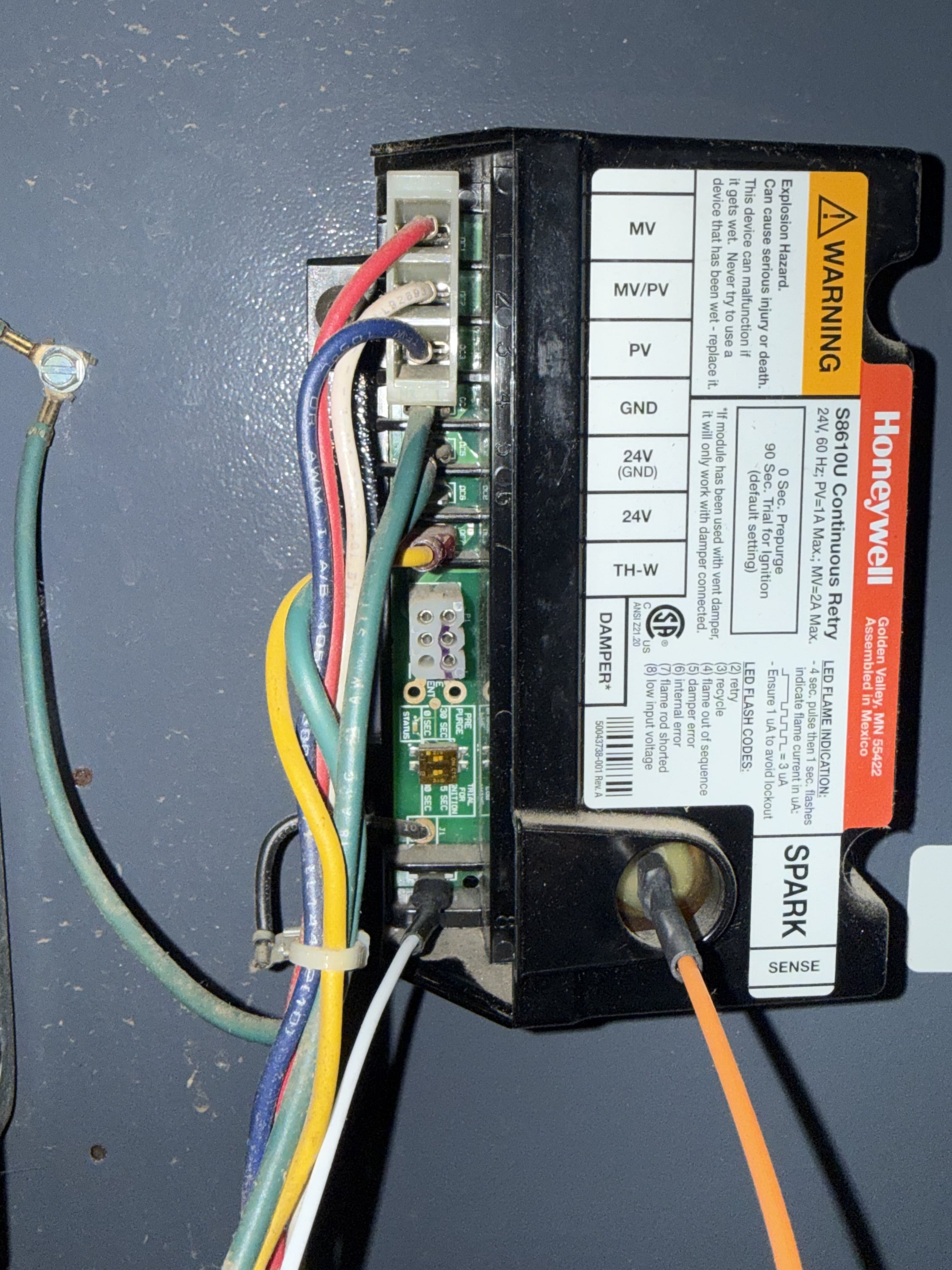
The new Ecobee thermostat won't turn on without the green wire connected, and I'm having difficulty figuring out which wire terminal to connect it to.
I haven't powered it up yet I don't want to damage it by connecting it under the wrong terminal.
Can someone kindly advise me as to which terminal to connect the green wire to get power to the thermostat? Or do I need an isolation relay to get power to it?
Thank you.
Comments
-
you ran a New 18/3wire?
0 -
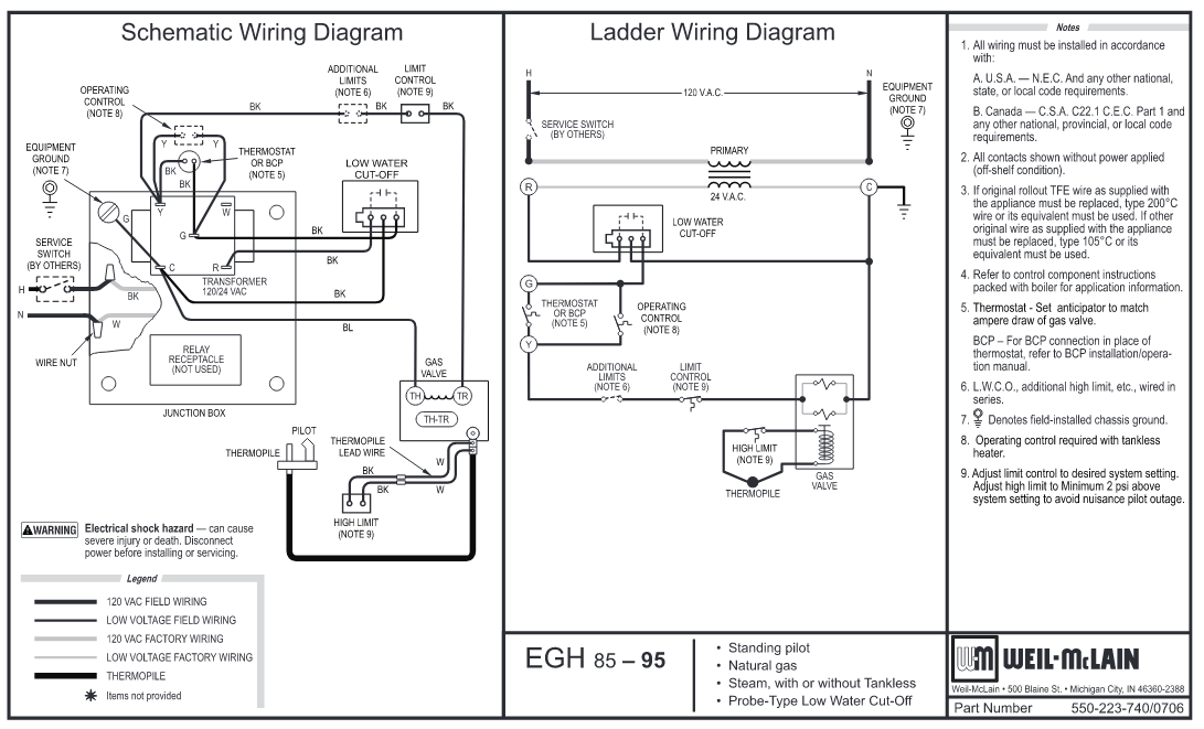
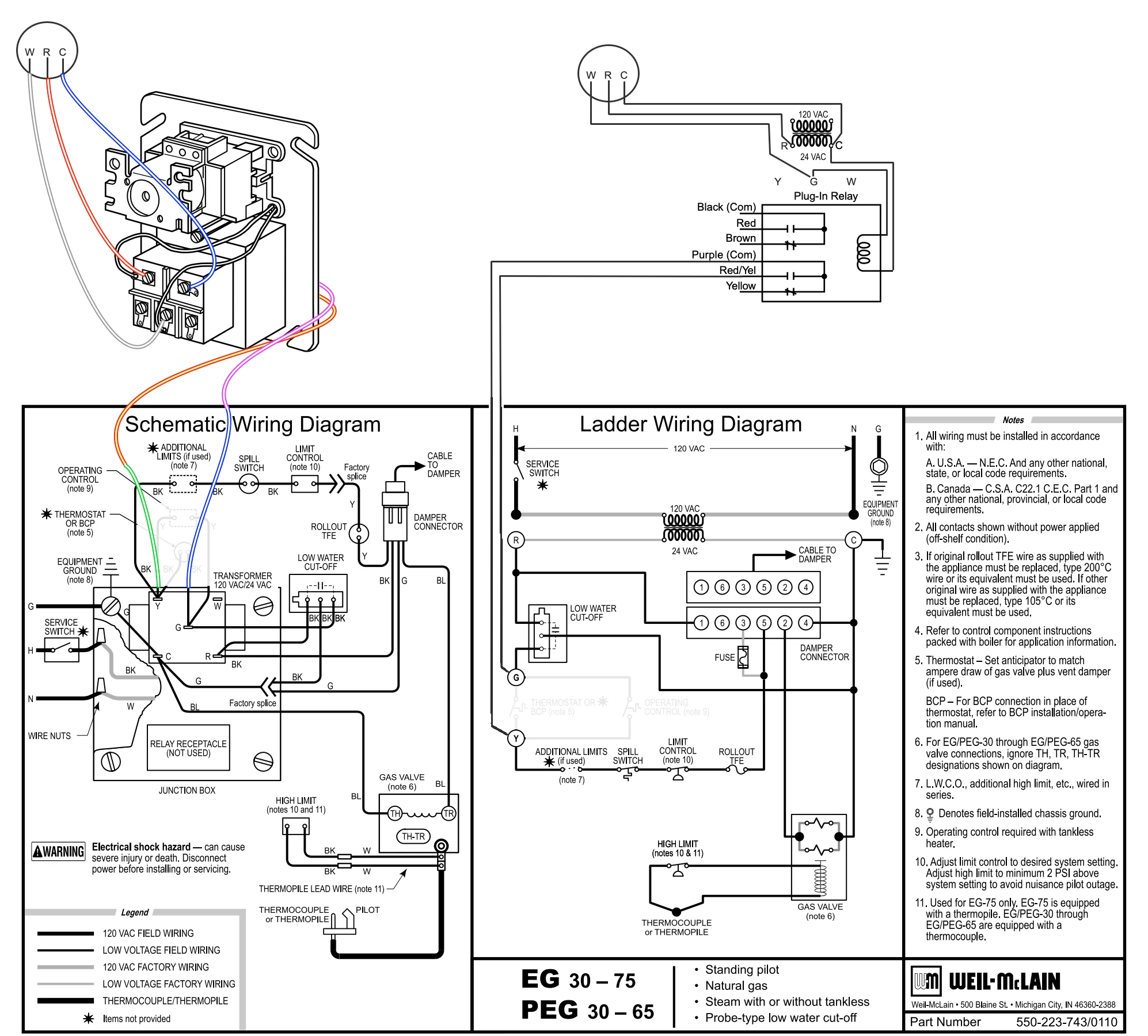
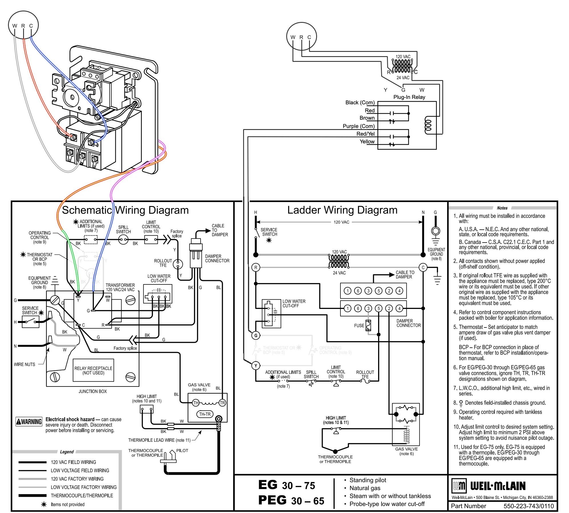
This is hopefully a similar wiring diagram to your boiler, although you probably don't have a standing pilot.
Is your LWCO a probe type ? If so the first thing connected to the Transformer's R terminal is the LWCO and not the thermostat.
You will probably need to add relay. Since the LWCO and the Ecobee thermostat both want constant 24 VAC power.
The Ecobee thermostat's R and C would connect to the transformer's R and C. This provides constant power to the Ecobee. The coil of the added relay would go to the Ecobee's W terminal and the transformer's C terminal. The contacts of the added relay would connect to where the original 2 wire thermostat was connected. I bet @EdTheHeaterMan has a wonderful wiring diagram all ready prepared as to how to add the relay.
 National - U.S. Gas Boiler 45+ Years Old
Steam 300 SQ. FT. - EDR 347
One Pipe System0 -
Yes, original Thermostat was in a less than ideal location. We relocated it to a different room, and while we were at it, we ran a new 18/3 wire.
0 -
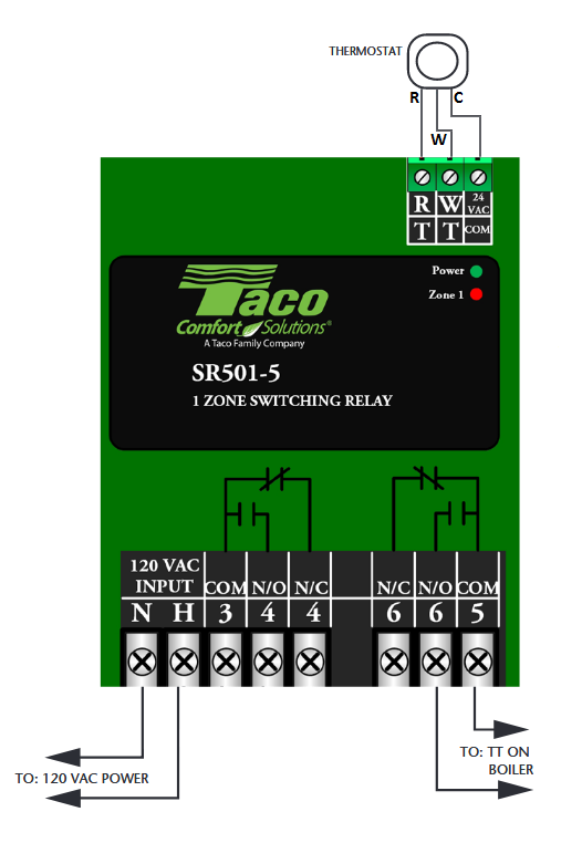
@109A_5 is correct, you'll need a relay. Any good relay with a 24-volt coil should be fine. I like these:
https://www.supplyhouse.com/Resideo-R8222B1067-24V-General-Purpose-Relay-with-SPDT-Switching?utm_adgroupid=177827080713&utm_targetid=pla-304229468133&utm_product_id=R8222B1067&utm_matchtype=&utm_adtype=pla&utm_category=Heating&gad_source=1&gad_campaignid=22340288845https://www.supplyhouse.com/Resideo-R8222D1014-24V-General-Purpose-Relay-with-DPDT-Switching?srsltid=AU7gw4Xku8dWswZL5xNkHq3e2GQSV7JbShnKdCk8hv8mOG6FFDIpxr-E
0 -
That method works well on hot-water systems with zone valves, because of the extra transformer capacity. The relay isolates the ZVs from the boiler, eliminating the chance of getting wires crossed and frying the transformers.
0 -
That is why I posted that diagtam where it is easy to find. Thanks @109A_5 for sharing it. But somehow there is a black line where some wires should be. Here is the corrected version.
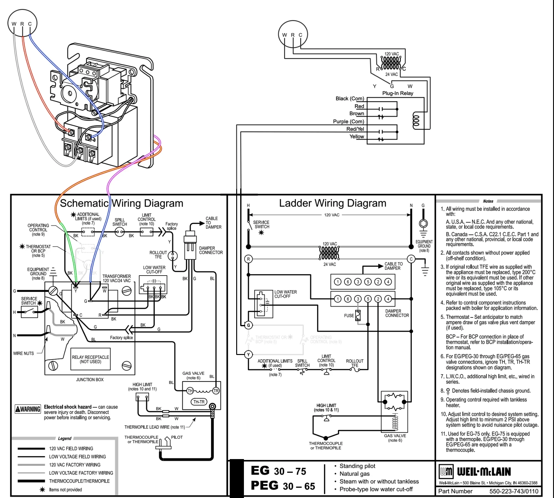
I also went back to the original post and corrected it too. Thanks Again @109A_5
Edward Young Retired
After you make that expensive repair and you still have the same problem, What will you check next?
0 -
@EdTheHeaterMan as soon as you try to copy and past that original in the other thread into something else that black bar appears, maybe it is your copyright security thing, here is my edit, I did not have time to mess with it before.
 National - U.S. Gas Boiler 45+ Years Old
Steam 300 SQ. FT. - EDR 347
One Pipe System 1
-
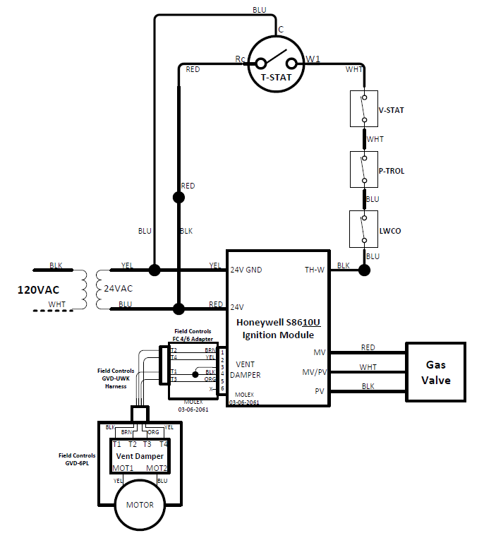
I was in an identical boat about 5 years ago. I installed an Ecobee wi-fi thermostat and had to replace my 2-wire thermostat with a 3-wire.
At the same time I installed a vent damper which required me changing the Honeywell S86F Ignition Module to a Honeywell S8610U which had the correct pinout for the vent damper I was using.
Long story short, I connected the "C" wire from the thermostat directly to the 24V side of the existing transformer. Below is a diagram I made so I wouldn't have to reverse engineer it again.
 0
-
I fixed it for future use. That seems to happen from time to time as a result of the default settings of PaintBrush where a "no color applied" area in my drawing appears white. Then someone copies it to program that shows
"no color applied" areas as grey or black. I wish I could find a way to cut and paste things without leaving the ares where I "Cut" or "Delete" leaves it white and not blankEdward Young Retired
After you make that expensive repair and you still have the same problem, What will you check next?
0 -
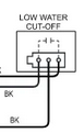
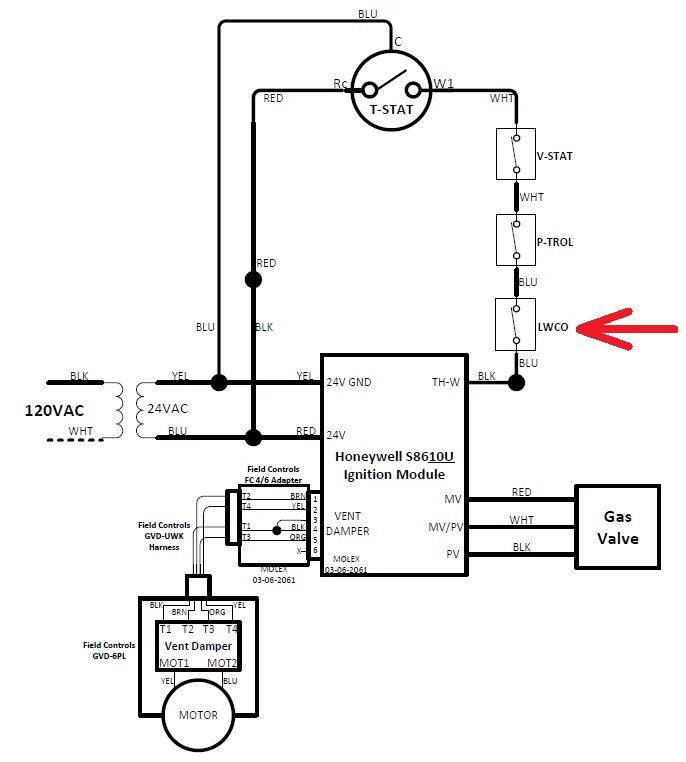
@AdmiralYoda I don't know what type of LWCO you have but the contacts portion are in a different place in the limit string as compared to @TheClevelandSteamer's boiler you may have removed a jumper and wired the your LWCO power and contacts independently. There are different ways of getting it to work depending on the system's equipment.
With @TheClevelandSteamer's WM boiler if his LWCO uses the 3 circuit connector isolating the LWCO power and the contacts may be more difficult.
 National - U.S. Gas Boiler 45+ Years Old
Steam 300 SQ. FT. - EDR 347
One Pipe System0 -
In this case I originally just did a copy and paste, from one thread to another.
National - U.S. Gas Boiler 45+ Years Old
Steam 300 SQ. FT. - EDR 347
One Pipe System0 -
@109A_5 I have a Peerless G-461-SP-1 installed in 1986. The G-461 was the naming convention before Peerless changed ownership in the 80's. It then became the 61 series and then eventually the 63 series. My old Peerless uses a float style LWCO. The contacts are closed when the float is up and open when the float drops to a certain level.
My main point was that he can just tap off of the 24VAC side of the transformer to power the C wire.
According to the Ecobee spec sheet it uses "Up to" 3.5VA, which on a 24VAC source is less than 150mA of current so there should be enough headroom on the transformer to handle the Ecobee.
Other options do exist. He could have another 24VAC transformer wired in just to power the Ecobee. If a 120VAC receptacle is nearby they make plug-in transformers to tap in to as well.
Ecobee also makes a "Power Extender Kit" which essentially taps off the 24VAC on the existing transformer for you and sends power to the C wire.
0 -
@AdmiralYoda In this case (the way I see it). looking at the WM wiring diagrams powering the Ecobee is really not the true issue. What to do with the Ecobee's W wire is. This is because both the LWCO and the Ecobee want full time 24 VAC power and full time burner control. The Ecobee wants to control the burner to regulate the living space temperature. The LWCO wants 100% control for safety.
If you put the Ecobee first in the control chain the LWCO is turned On and Off with each thermostat cycle.
If you put the Ecobee after the LWCO (Ecobee R to the boiler's G) when the LWCO trips the Ecobee looses power which confuses people, also and if you have a LWCO that does that goofy shut the burner down often for a test thing that makes it ever weirder.
As far as your Peerless G-461-SP-1 system it is simpler since you have a float and not a probe circuit that needs power and just a set of contacts to deal with.
National - U.S. Gas Boiler 45+ Years Old
Steam 300 SQ. FT. - EDR 347
One Pipe System0 -
Back to basics. The Ecobee — and almost any other "smart" or wi-fi or otherwise wireless thermostat that I know of — requires constant power.
And, remarkably, they are pretty consistent about it. you need 24 volts AC power available between the R and C connections on the thermostat. For control, the thermostat makes or breaks a contact between W and, almost always, R.
Back at the controlled device, there are two classes of them: those that need power (zone valves, relay coils, that sort of thing) and those that don't — the most common example being the burner control.
And it's at that point where folks who don't follow basic electricity get caught up. If you are dealing with device needing power, your circuit is going to be power supply A to R connection, then the W connection to one terminal of the device, then from the other terminal of the device back to the power supply B. If the device wants a closed contact but not power, then you power supply is power supply A to R and C to power supply B. The device is connected device to R, out W and back to the device. Neither W on the thermostat or — perhaps more important — either of the device terminals! — connects in any way to the power supply.
All your other safeties and controls are also dry contacts,, except powered LWCOs, and can be on the controlled device — thermostat — device circuit somewhere, in series. A powered LWCO is treated the same way as the powered thermostat (but note that if you use the same power supply as is used for the thermostat you are going to need a relay to convert either it or the thermostat into a dry contact type control…)
Br. Jamie, osb
Building superintendent/caretaker, 7200 sq. ft. historic house museum with dependencies in New England0




Categories
- All Categories
- 87.8K THE MAIN WALL
- 3.3K A-C, Heat Pumps & Refrigeration
- 60 Biomass
- 430 Carbon Monoxide Awareness
- 133 Chimneys & Flues
- 2.2K Domestic Hot Water
- 6K Gas Heating
- 124 Geothermal
- 170 Indoor-Air Quality
- 3.9K Oil Heating
- 79 Pipe Deterioration
- 1.1K Plumbing
- 6.7K Radiant Heating
- 397 Solar
- 16.1K Strictly Steam
- 3.5K Thermostats and Controls
- 56 Water Quality
- 51 Industry Classes
- 51 Job Opportunities
- 18 Recall Announcements