Pump Curves, then and now
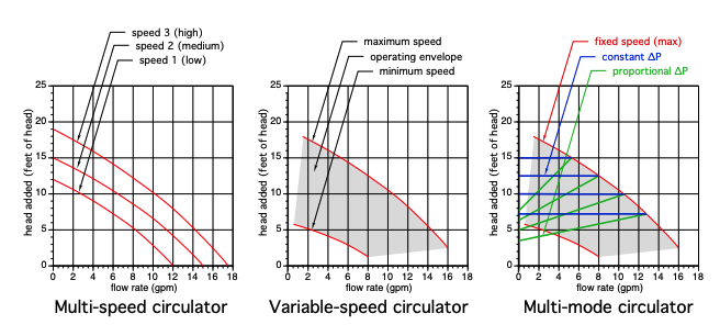
Typical single or multi speed circs had a defined curve(s).
Variable speed have a window or envelop of curves between minimum and maximum. Varying the speed can be done with after market controls, tekmar, HBX and most electronic solar differential controls, for example. Or some circulators have this function onboard.
Today's multi mode circulators have a number of curves within the envelop, depending on the selected mode.
The type of system piping helps determine the best mode selection.
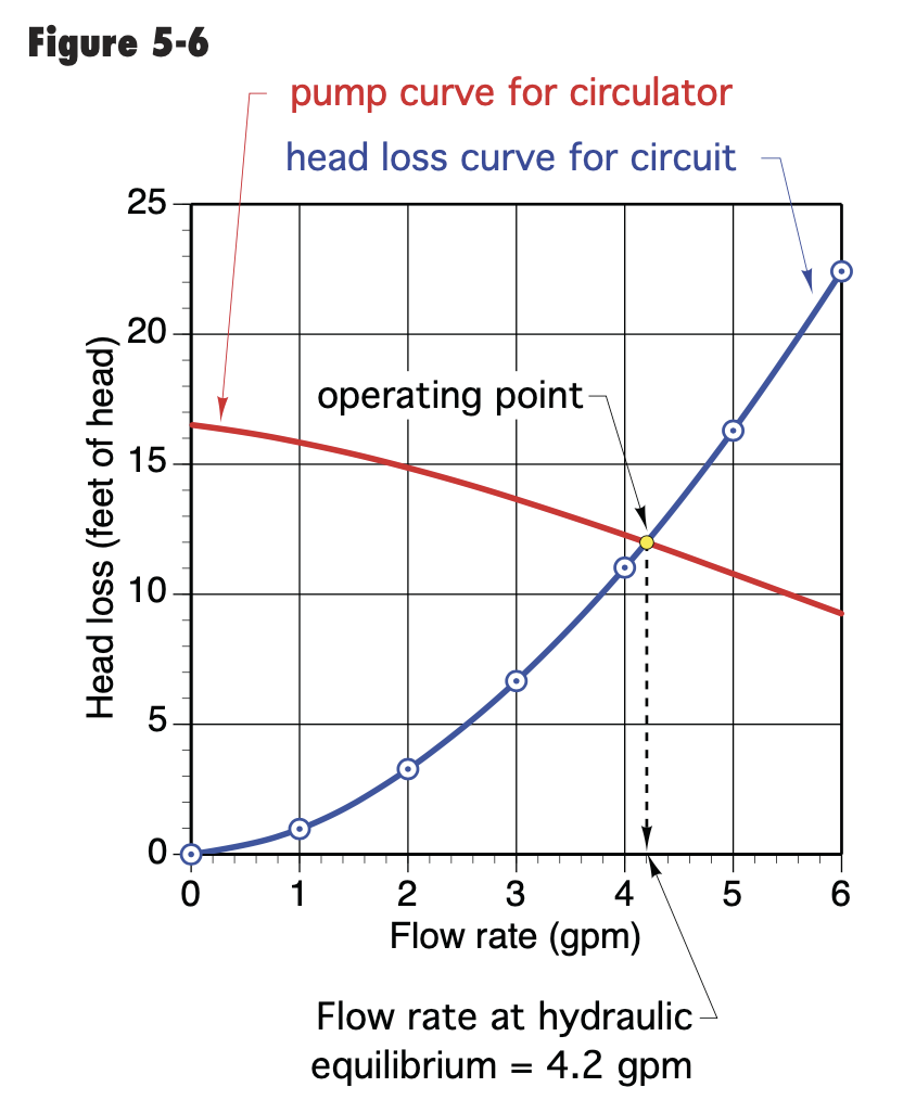
If you analyze or define the system curve with multiple points you would lay that "system" curve over pump curve to find the actual OP, operating point.
trainer for Caleffi NA
Living the hydronic dream



Comments
-
Picky picky me. I have to admit that I'm not at all keen on using the term "pump curve" for the operating characteristics of a variable controller. To me, the term "pump curve" really should be limited to describing the way the flow through the pump varies with the head or pressure (take your pick) across the pump at a specific rpm of the driver, and goes along with a set of other curves, such as efficiency and power requirement.
As soon as a variable speed driver enters the picture, you are looking at the characteristics of the controller as much as the pump, within the range of speeds which the controller can run the driver at. "constant delta P" or "proportional delta P" or "constant delta T" or whatever really isn't a pump property at all — it is a property of what parameters are measured and where, and what (usually computer) logic is used to control the pump itself.
Br. Jamie, osb
Building superintendent/caretaker, 7200 sq. ft. historic house museum with dependencies in New England0 -
I agree with Jamie. There's also characteristics of electric motor to complicate this subject.
0 -
The pump curves define that pumps operating conditions. Run out at one end of the curve, shut off head at the other.
It could be spun by a diesel engine , water fall, bicycle, or team of horses.
Those pumps with those motor will work within the shaded area.
Larger pumps will have BEP and BHP curves on the sheet also. I have never seen that info on small residential circulator pumps, which is what these graphs depict.
Smart pump technology allows the electronics to learn the systems conditions and auto adapt. So the latest technology gives the pump some intelligence.
The motor adjustability and control logic can do so much At some point the impeller and volute needs to be changed
Bob "hot rod" Rohr
trainer for Caleffi NA
Living the hydronic dream1 -
Is the term duty point the same as the operating point?
Pump curves are published as are heat exchanger (HX) curves for boilers and indirect water heaters. Determining total system curves that include head loss for all HX's involved plus all the piping and installed devices can be a guessing game, at least for me when I'm in a hurry to choose a pump for a job. It usually works out.
I've seen large jobs that specify a trimmed pump impeller to match the system curve.
8.33 lbs./gal. x 60 min./hr. x 20°ΔT = 10,000 BTU's/hour
Two btu per sq ft for degree difference for a slab0 -
I learned to calculate pump head on my own just reading about it. Tedious? Yup. I never bought into the pipe pus 50% for fittings. I always counted every feet of pipe and counted the fittings. Yes, there are times you can't see all the pipe or all the fitting so you calculate what you can see and guess the rest.
Not a pump expert or a pump curve expert. Most of the jobs I got called in to "fix" were commercial jobs.
I would figure out the GPM needed and then calculate the head. Once I had the head and gpm and the fluid (water or glycol) I would call the pump supplier weather it was Armstrong, Taco or Patterson (Patterson had a good quick ship program that didn't cost too much extra) and order the pump(s) and let them make the selection.
The one thing that blew my cork was that the company I worked for sent 3 different people to B & Gs "Little Red Schoolhouse", I wasn't one of them. But when there jobs wouldn't work because of any piping or pump issues I got sent to fix them. I wanted to go to B & G myself but it never happened.
And not one of them could size a pump.
It was merely a vacation and a lot of beer drinking for them.

 2
2 -
How accurate is adding up theoretical head losses?
Selecting correct pump is ideally job at test or commissioning stage. Requires system curves when all terminals are off and when all are full open. Correct pump is happy working in that region. Variable speed may work but is it happy? Has anyone seen this procedure where a temporary pump is used to determine actual system curves and then permanent pump is chosen?
0 -
The B&G System Sizer was the go to calculator for years.
Find an older B&G rep and they were quick and accurate with the wheel.The calculation are even faster and more accurate with software. Assuming the correct info us being put into the “machine”
The typical PSC residential circulator 007, 15-58, etc only run around low to mid 20% wire to water efficiency. So not much data goes along with those pumps.
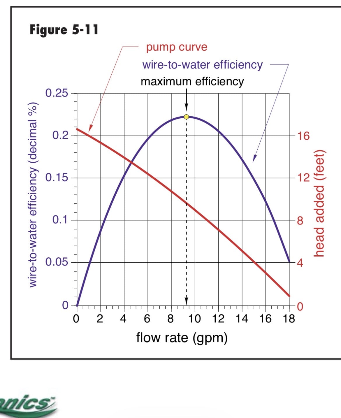
When you start talking larger pumps it makes sense to look at performance. Frequency drives are helpful for dialing in a pump also. But they are turning electricity into heat also.
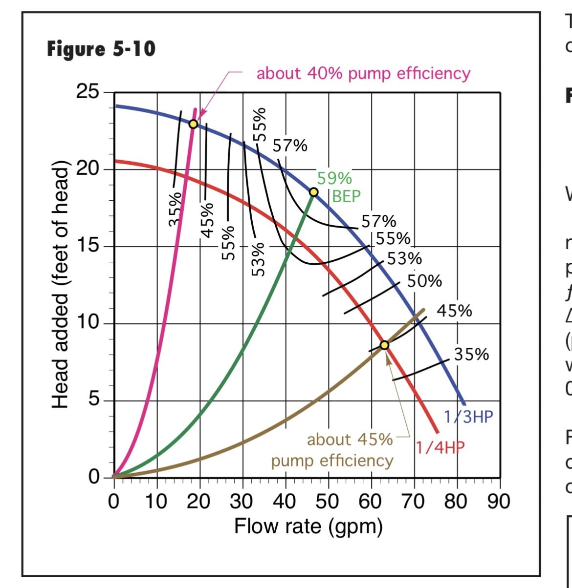
we have an Idronics on determining existing systems
 Bob "hot rod" Rohr
trainer for Caleffi NA
Living the hydronic dream0 -
Thank you for the system curves up there, @hot_rod ! One minor additional detail — much of the loss of efficiency in a centrifugal pump (which includes almost all circulators I've ever heard of!) when they are operating off their peak efficiency point or curve is inherent in the pump itself — and just dialing the variable drive control up or down to get a pump to operate at a flow and head combination off of that still drops the efficiency — and raises the cost of running the pump.
Even in small residential settings one really should try to get a pump which matches the system, and not rely solely on electronic jiggery-pokery to make it work.
Br. Jamie, osb
Building superintendent/caretaker, 7200 sq. ft. historic house museum with dependencies in New England0 -
I always had a B& G wheel in my truck
They have the electronic version you can download online for free the "System Sizer"
better than the wheel it lets you convert from water to glycol % and adjust fluid temp if needed and some other stuff.
0 -
Don't care so much about electric consumption as about pump destroying itself by operating at too low efficiency. Not a big deal when I just have to switch out cartridge. But when there's no isolating valves and you have to remove pump…..
1 -
There's another curve which I've seen for big pumps — NPSH (net positive suction head) required. Part of the problem there is that it's temperature dependent as well as flow dependent, so the curves are a bit messy. But it is a real problem even with small pumps like circulators, since dropping below it will cause cavitation, which can eat up an impellor in remarkably short time.
Br. Jamie, osb
Building superintendent/caretaker, 7200 sq. ft. historic house museum with dependencies in New England0 -
Supposedly not a problem in closed circuit BUT that assumes system is correctly pressurized. When equipment is in penthouse eventually booboo happens. Especially when pump is oversized.
Another good practice is that there's a length of straight pipe into and out of pump.
 1
1 -
One of the better reasons for pumping away…
We see it once in a while on strict hot water systems — but I seem to recall a number of examples whee people were tapping a hot water loop off a steam boiler.
Br. Jamie, osb
Building superintendent/caretaker, 7200 sq. ft. historic house museum with dependencies in New England0 -
I have calculated NPSH a few times.
From what I understand it is not an issue in a closed loop as @jumper mentioned.
On an open system yes, it can be an issue like cooling towers but usually isn't a problem there either if the suction line is piped right and the pump has a suction diffuser that straightens the flow.
Where it really can rear its ugly side is on condensate and boiler feed pumps when the water is allowed to overheat due to bad traps.
0 -
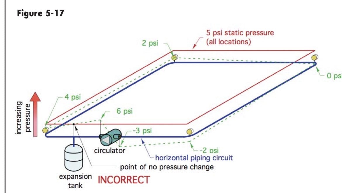
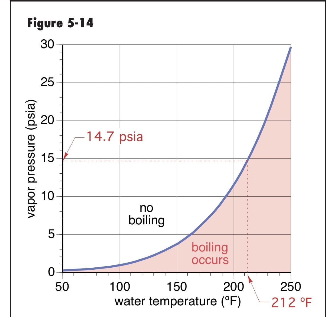
The small Grundfos circulators show 1.7 psi at 140F, something like 4 psi at 190F, NPSHr
pumping at the expansion tank, low fill pressure can put you in a cavitation condition.
Temperature and pump delta P are part of the equation also
 Bob "hot rod" Rohr
trainer for Caleffi NA
Living the hydronic dream0 -
I'm curious of the temporary pump to determine what's needed for the system as well.. has anyone tried this and if you have how did it turn out and what did it all show? I was thinking about picking up a circulator and using it as a tool for this as well.
0 -
»curious of the temporary pump to determine what's needed for the system as well.. «
Over the years I've asked designers, TAB, and commissioning companies. Interesting but nobody is enthusiastic about asking clients to pay. Modern campus district cooling has instrumentation and variable speed drives to determine system curves for every situation. But I've never heard about anybody switching out pumps to comport with data.
0 -
If you have little information on a system, and it is mostly hidden, and it is simple — one circuit — then that would be one way to obtain the flow vs. head loss curve for it. You would need to at least be in the ballpark, though, with your test pump, as being out on the edges of performance will not be any too accurate.
In my opinion, if you have a pretty good idea of the system, though, you'll do just fine by adding up the head losses with whatever tables or computation gadgets you have.
If you have to precision fine tune the flow, you are going to need to overshoot and use a throttling valve anyway.
Br. Jamie, osb
Building superintendent/caretaker, 7200 sq. ft. historic house museum with dependencies in New England0 -
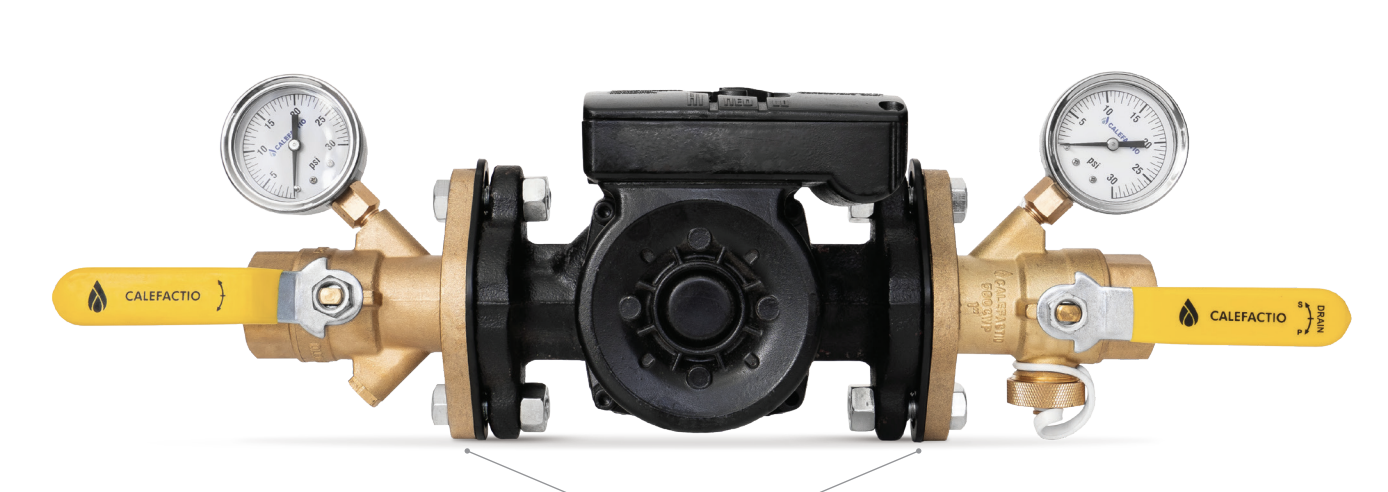
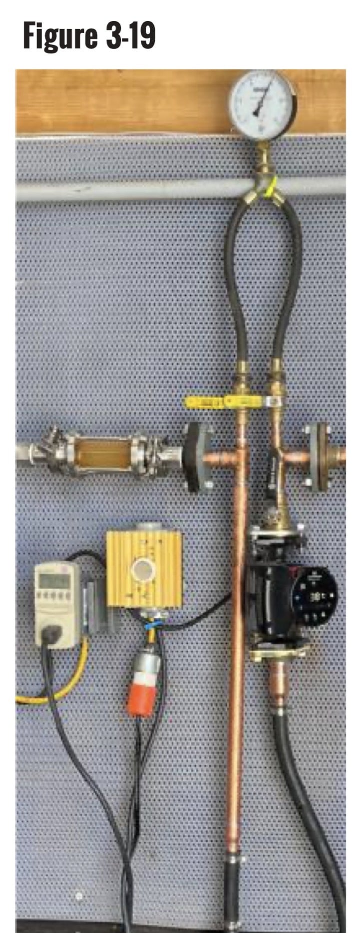
Calefactio makes ΔP pump flanges. Subtract the two PSI readings, convert to ft. of head and you've found your duty point on the curve.
 8.33 lbs./gal. x 60 min./hr. x 20°ΔT = 10,000 BTU's/hour
Two btu per sq ft for degree difference for a slab0 -
They used to say gauges are not accurate enough for that but I have done that and it is usually close enough.
0 -
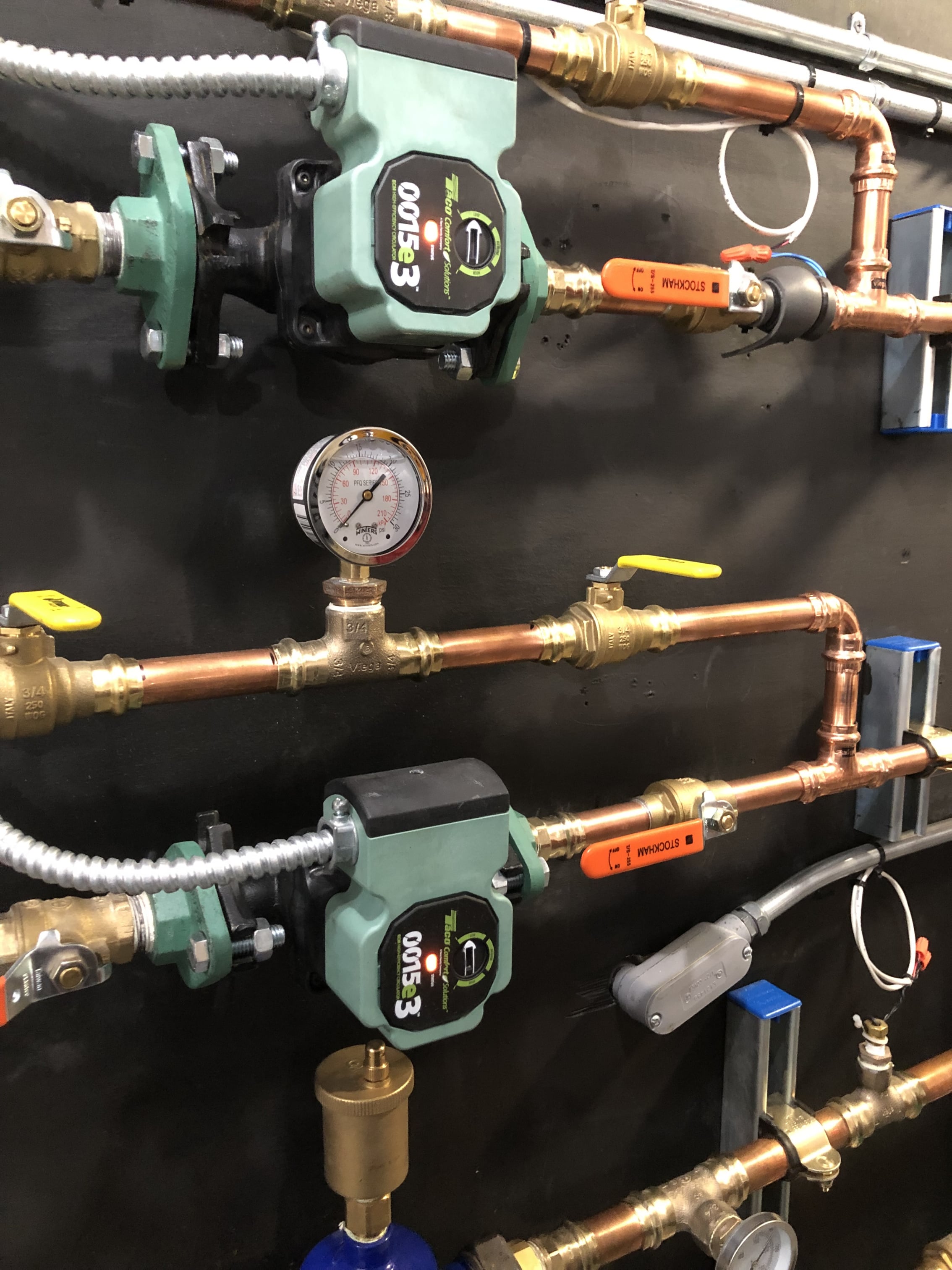
A good quality, large face, 15 psi gauge for measuring residential circ. Use one gauge for best accuracy
 Bob "hot rod" Rohr
trainer for Caleffi NA
Living the hydronic dream1 -
-
Yes, one gauge is the way to go, liquid filled is the best.
Not cheap though
0 -
It was my system so I just went with it.
Steve Minnich1


Categories
- All Categories
- 87.8K THE MAIN WALL
- 3.3K A-C, Heat Pumps & Refrigeration
- 59 Biomass
- 430 Carbon Monoxide Awareness
- 133 Chimneys & Flues
- 2.2K Domestic Hot Water
- 6K Gas Heating
- 124 Geothermal
- 170 Indoor-Air Quality
- 3.8K Oil Heating
- 79 Pipe Deterioration
- 1.1K Plumbing
- 6.7K Radiant Heating
- 396 Solar
- 16.1K Strictly Steam
- 3.5K Thermostats and Controls
- 56 Water Quality
- 51 Industry Classes
- 51 Job Opportunities
- 18 Recall Announcements