Replacing a mini split system

I have a Shinco 18000 btu mini split that is about 10-12 years old. Shinco parts are hard to find because the company has changed hands and is not selling mini split systems anymore. I’ve replaced some sensors and the unit was working perfectly but lately it’s not functioning properly. I’m thinking ahead and planning to have it replaced. It was installed during a remodel and all of the lines and wiring is in the walls. Can the unit wiring and refrigerant lines be reused when the unit is replaced?
Comments
-
it depends! more than likely yes, the lines can be reused. I would make note of what size and length these linesets are and keep it in your permanent records though because that info does matter!
 1
1 -
what size and type wire is between the indoor and outdoor sections?
You have to see if it’s compatible with the new system
do not assume the line sizes are correct either
0 -
I have been on jobs that require a 4 wire 16 or 14 gauge wire between the indoor and the outdoor unit and some knucklehead used 18-4 thermostat for that purpose. the reason I was called in was because the unit(s) were not operating properly. I determined that the line-sets were leaking and the connecting wires needed to be upgraded. That was an nightmare job because the wires were enclosed after the rough-in was completed.
Edward Young Retired
After you make that expensive repair and you still have the same problem, What will you check next?
0 -
Thanks for the responses. I will have this job done by a HVAC contractor that I know. The refrigerant lines are of course more of a concern. New wiring from inside and outside units is not a problem to run if necessary.
0 -
Looking at the power requirements for the indoor units, 18ga wire should work just fine, the current drawn by the indoor unit is tiny.
But there are two problems with using 18ga wire for this purpose 1) The power for the internal unit is usually tapped directly from the supply conductors to the minisplit. This means that the wires to the indoor unit are protected at 15 or 20A. If something goes wrong, then the breaker protecting the minisplit won't properly protect the 18ga wire. 2) Thermostat wire is generally not rated for 240V; most normal building wire is rated for 600V and then used at 240V.
I am writing the above to explain why the improper wire worked for a while, but was a safety hazard. I guess I'm also writing to suggest to the HVAC world that maybe proper fuses could be built into the main unit to permit the use of properly rated 16ga or 18ga wire.
-Jonathan
 1
1 -
Agree with @winnie… The outdoor unit may have 15 or 20 amp rating on many mini-split systems. As far as the 4 wires that connect the outdoor unit to the indoor unit is concerned, the 4 connecting wires are specified based on the indoor unit configuration and what the indoor fan motor may require. The other two wires are most likely communication wiring. If a smaller gauge wire is allowed, then that will be fused at the outdoor unit at some point before the smaller gauge wire connection. there have been some specifications that recommend a shielded 4 wire cable between the indoor and the outdoor unit. When this specification was not followed because the supplier did not carry the proper wiring, there were a lot of calls to tech support. all of a sudden the suppliers started carrying shielded cable.
of course once that problem was resolved the newer units didn't require that shielded cable so back to the lower cost wire. the fun we had learning about foreign stuff.
Edward Young Retired
After you make that expensive repair and you still have the same problem, What will you check next?
0 -
Most units feed the indoor head power through a 10A or so fuse inside the outdoor unit. Usually the problem is that is hard to find 18 guage wire that is rated for in wall and outdoor. Usually the simplest is to wire with 14-3 or 14-4 NMWU (standard outdoor Romex).
Buy a set of flare plug caps for the lineset you have and have the installer put them after recovering the refrigerant. Very easy to get crud into open linesets when working.
0 -
you also don't want moisture in the linesets, it is hard to get out without heating the linesets.
0 -
thermostat wiring is usually rated for 300v but isn't an approved wiring method for line voltage wiring. mostly that rating allows you to put it in the same raceway as is feeding line voltage to utilization equipment that is supplied by that line voltage wiring and controlled by that low energy wiring.
0 -
If new wiring isn't a problem if necessary, then new refrigerant lines shouldn't be a problem if necessary. Are you positive the old system was sized correctly?
Is it just one 18K head, or multiple heads? If say you've got a 10K and a 8K, some (legit) manufactures don't make those sizes. They're typically 6,9,12,15,18. So now what? Size the new system on the design load. And if the existing line sizes are ok, good. If they're not, they're not.
You're not going from Shinco to Mr. Cool, are you?
0 -
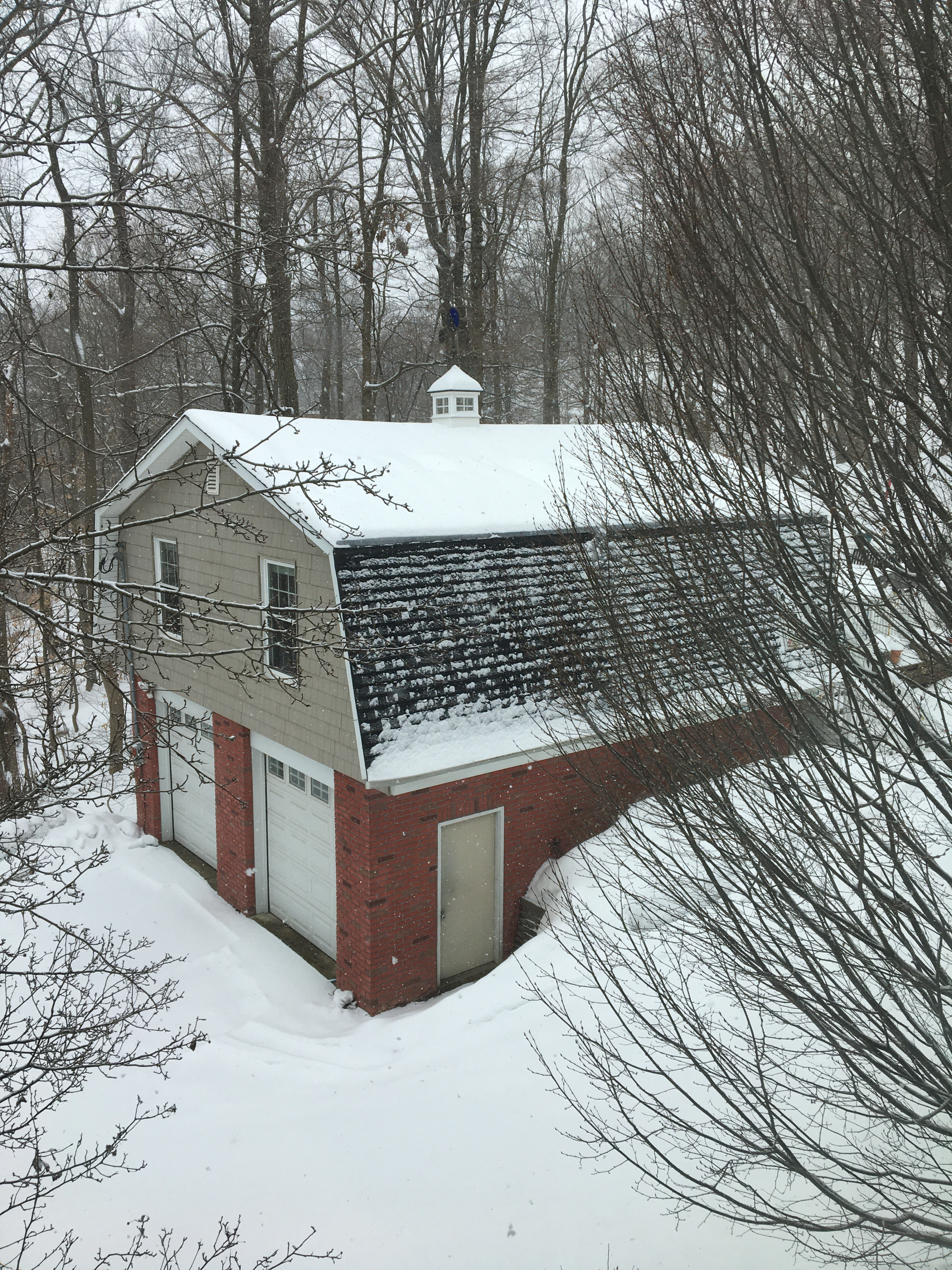
HVACNUT, when the existing unit was installed the room was an unfinished space,just exposed studs in a room over a detached garage. I’m sure a new line set and wiring could be installed but using the existing ones would make it easier. I will discuss this with my contractor the decision will be his. I recently had a central system in my house replaced the original refrigerant lines were used. The room is 600 sq. feet, second floor, moderate sun exposure with 10 foot ceilings. The current unit is 18k with both AC and heat.
0 -
We need to know the replacement unit model #, and the length and size of the original line set as well as wire size and type to properly answer the question.
1 -
pecmsg, I don’t have any replacement in mind. My choice would be to find something that is compatible with the existing lines if possible.
0 -
Thats the wrong way to size a mini………………. sorry
0 -
25x25 freestanding detached garage. The room is second floor with unheated space below, floor is uninsulated. Ceilings are 10’ walls and ceiling are insulated low attic above. There ia a kitchen area with oven/range. Would 1ton mini split heat pump be enough for AC and heat? The 13 year old 18,000 btu unit to be replaced has worked fine. There is a ceiling mounted electric garage heater in first floor garage set at 45 degrees.
0 -
do a heat loss analysis; it will give you a much better result
0 -
I just checked the circuit diagram for my minisplits, and I stand corrected. There is a fuse between the power source and the connection to the indoor unit. However according to the diagram, the fuse is only in one leg of the supply. A fuse in one leg of the supply is not quite correct for the L-L supply used in the US, because it won't protect a fault between the other circuit leg and ground.
The diagram may be wrong, or may be for the non-US market where 230ish volt power is L-N. The diagram does label the terminals L and N, not L1, L2.
-Jonathan
0 -
I disagree. When a 120 VAC appliance is operated, only the L1 line is fused; the neutral is not.
As far as the 10 amps or less needed to operate the indoor fan motor on a mini-split is concerned, only one fuse would be required. Current cannot complete the circuit if either leg of the power-supply wiring opens because of an overcurrent condition.
Keep in mind that the source of those two conductors feeding the indoor unit is NOT the 220–240 VAC supply from the circuit breaker, or fuse panel. The inverter in the outdoor unit converts the incoming household power to DC and then supplies the indoor unit. The inverter is the source. Just as is the transformer on the utility poll is the source for the electricity to your home.
Think of it like a 24 VAC transformer. You rarely see two fuses on a circuit board or two fuse holders on the 24-volt load side of the transformer. Only the R conductor is fused; the C conductor is not. The feed from the outdoor unit to the indoor unit is no different.
This does not conflict with any code requirement for operation in the United States.
Edward Young Retired
After you make that expensive repair and you still have the same problem, What will you check next?
0 -
if it shorted to ground it would trip the branch circuit overload protection almost instantly, it woudln't damage the smaller conductor.
0 -
Fujitsu requires fuses be installed on the control wires at the outdoor connection point. Simple enough
0 -
My choice seems to be 12,000 or 18,000 btu’s. My best choice would probably be 18,000 being in Northern NJ with moderate weather, kitchen with oven/range, dishwasher, 3 piece bathroom and washer/dryer. Although it’s not a concern of mine now the garage underneath could potentially have two recently driven cars put inside in August and there’s no floor insulation.
0 -
You could use type TC (control tray cable) You have to buy it with the correct jacket for its intended use.
Weather resistant, in raceway etc. Automation Direct is one supplier.
This is used sometimes in residential generator installations. You would have to look it up but the NEC allows it for certain uses.
0 -
Type TC is listed for outdoor use, but it must be in raceway or cable tray indoors. Might as well use something that doesn't need to be in raceway indoors.
The supply houses around here have been including a 500' roll of some fancy MC-based cable, with a jacket for outdoor use, with every system bought. I've also come across something called IIRC "Duck Cable", which is a Siamese cable, 3x #14s & a pair of 18ish conductors. The web site insists it meets code & even has a paper to give to the inspector that says it meets code. It seems to be some kind of Romex with a really crappy outer jacket (One of the selling points is how easy it is to strip the jacket. It is. <sigh>).
0 -
as long as the wire is sized properly 14 gauge for 15 amp breaker 12 for 20 amp does it matter?
0 -
Type TC needs a raceway indoors, if you gotta go through all that work, might as well run THHN.
The Duck cable, well, the outer jacket can be stripped by hand, just by pulling on it. Or catching it on a sharp edge. Or a not so sharp edge. Or, in fact, nearly anything. And while the paperworks are adamant that it's approved, I don't recall seeing any Code references.
The coated MC cable seems like it would be the easiest solution for the all-high-voltage style of mini splits, but the Duck cable might be better for the type that communicate over a low-voltage pair. Assuming the AHJ believes the paperworks.
If the supplier wants to include some cable, fine—but I really don't want to buy a 500' roll for a head with a run that 100% of the time will be less than 200' and very often less than 100'.
Just to pass on some of my experience.
0 -
from the 2023 NEC. 336.10.9
for 1 and 2 family dwellings type TC-ER-JB used for interior wiring shall comply with part 2 of article 334 (install same as Romex) and for exterior part 2 of article 340 (same as UF cable) Raceway not needed.
I see this used on generator installs and I have not used it on mini splits but I am told it is quite common.
Is approved for power & control circuits. I helped a buddy wire a generator with it a few years back and it was inspected and approved. Haven't done any minis in years
0 -
Huh, guess I never checked the resi code, I do commercial. Or it changed in the last decade. Thanks.
0 -
Type TC-ER-JP cable is what you want. TC is rated for outdoor use. 'ER' is for 'Exposed Run', and 'JP' is for being pulled through holes in wood members. You can use it outdoors fully exposed, and you can run it indoors like NM.
-Jonathan
0 -
I am looking at the circuit diagram for the Fujitsu AOU12RLFF and AGU12RLF. The system is rated for AC 208-230V, and is installed in the US.
The schematic diagram for the outdoor unit shows a direct AC connection between the supply terminal and the indoor unit connection terminals. There is a 5A fuse in one leg. The outdoor unit goes on to rectify the AC and use inverters to run the compressor and fan, but the indoor unit is shown as AC powered.
The schematic diagram for the indoor unit shows a 3.15A fuse in one leg, and the AC gets rectified to power the various indoor unit functions.
The instructions that came with the unit did not talk about adding any fuses between indoor and outdoor unit. The schematic diagrams specially call the supply 'L and N', not 'L1 and L2'. These diagrams may be for versions of the system intended for a different market, such as Europe, where 230V L-N is the normal supply. But if these diagrams are correct for the units that I have, then one leg of the supply to the indoor unit is protected by the supply breaker for the entire system, and one leg is protected at 5A via a fuse.
0 -
the national electric code is one thing
your local authority having jurisdiction has the finalsay in what kind of cable and how it can be run
0 -
@mattmia2 Quote: “If it shorted to ground, it would trip the branch-circuit overcurrent protection almost instantly. It wouldn’t damage the smaller conductor.”
Please describe what “it” refers to.
“It” could mean the power circuit between the indoor unit and the outdoor unit. If that is the case, and one of the DC power conductors supplied by the inverter to the fan motor and other loads in the indoor unit shorts to ground or to the other power conductor, it may or may not trip the 208–230-volt circuit breaker at the building’s power distribution panel (circuit breaker panel). It should, however, cause the fuse or other overcurrent-protection device in the outdoor unit' internal wiring to open.
You cannot assume that the building’s 208/230-volt breaker will adequately protect every smaller conductor between the outdoor and indoor units.
“It” could also mean the actual 208–230-volt wiring from the power distribution panel to the outdoor unit. If those conductors were to fail and short to ground or to each other, that would definitely trip the circuit breaker, as it should.
It all depends on how the failure occurs and which wire is the source of the fault. That is why you want to follow the NEC, along with any requirements imposed by the local AHJ when local conditions call for more restrictive rules.
Edward Young Retired
After you make that expensive repair and you still have the same problem, What will you check next?
0 -
@winnie quote: "The instructions that came with the unit did not talk about adding any fuses between indoor and outdoor unit."
Agreed. There is no instruction requiring the installer to add additional lower-amperage fuses or circuit breakers. Those protections are included in the outdoor unit and installed at the factory. Those are the fuses or circuit protection that I am referring to in the statement you referenced.
Here is some examples of circuit protection on a circuit board:
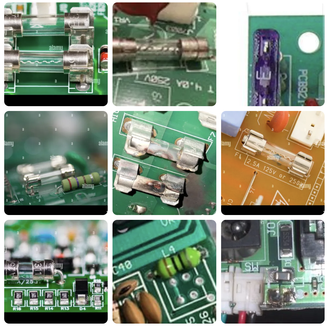
Bottom right and bottom center are not included. Thay just happen to be in the frame when I took this screenshot. The center square looks like the location of someones problem.
Edward Young Retired
After you make that expensive repair and you still have the same problem, What will you check next?
0 -
MFG instructions if the unit is UL or other testing lab certified you usually install as the MFG requires because if you don't you will violate the listing.
Similar to installing/venting gas fired equipment.
The MFg tell you the venting requirements because the gas code can't keep up with all the changes
So in most case the MFG instructions trumps the code.
@winnie cu on Mike Holt's forum welcome aboard. Guess you have been here a while.
0 -
I’m OP, thanks for all the information. When I replace my unit I will use the manufacturers wire if supplied or the recommended wire in the installation instructions. My main concern was if the existing copper lineset could be used, adapted if necessary, because they were inside the walls. New wiring is easier to run through the tight (but possible) attic space. I am hoping all the existing connections could be reused and will try to select a replacement based on that.
1





Categories
- All Categories
- 87.8K THE MAIN WALL
- 3.3K A-C, Heat Pumps & Refrigeration
- 60 Biomass
- 430 Carbon Monoxide Awareness
- 133 Chimneys & Flues
- 2.2K Domestic Hot Water
- 6K Gas Heating
- 124 Geothermal
- 170 Indoor-Air Quality
- 3.9K Oil Heating
- 79 Pipe Deterioration
- 1.1K Plumbing
- 6.7K Radiant Heating
- 397 Solar
- 16.1K Strictly Steam
- 3.5K Thermostats and Controls
- 56 Water Quality
- 51 Industry Classes
- 51 Job Opportunities
- 18 Recall Announcements