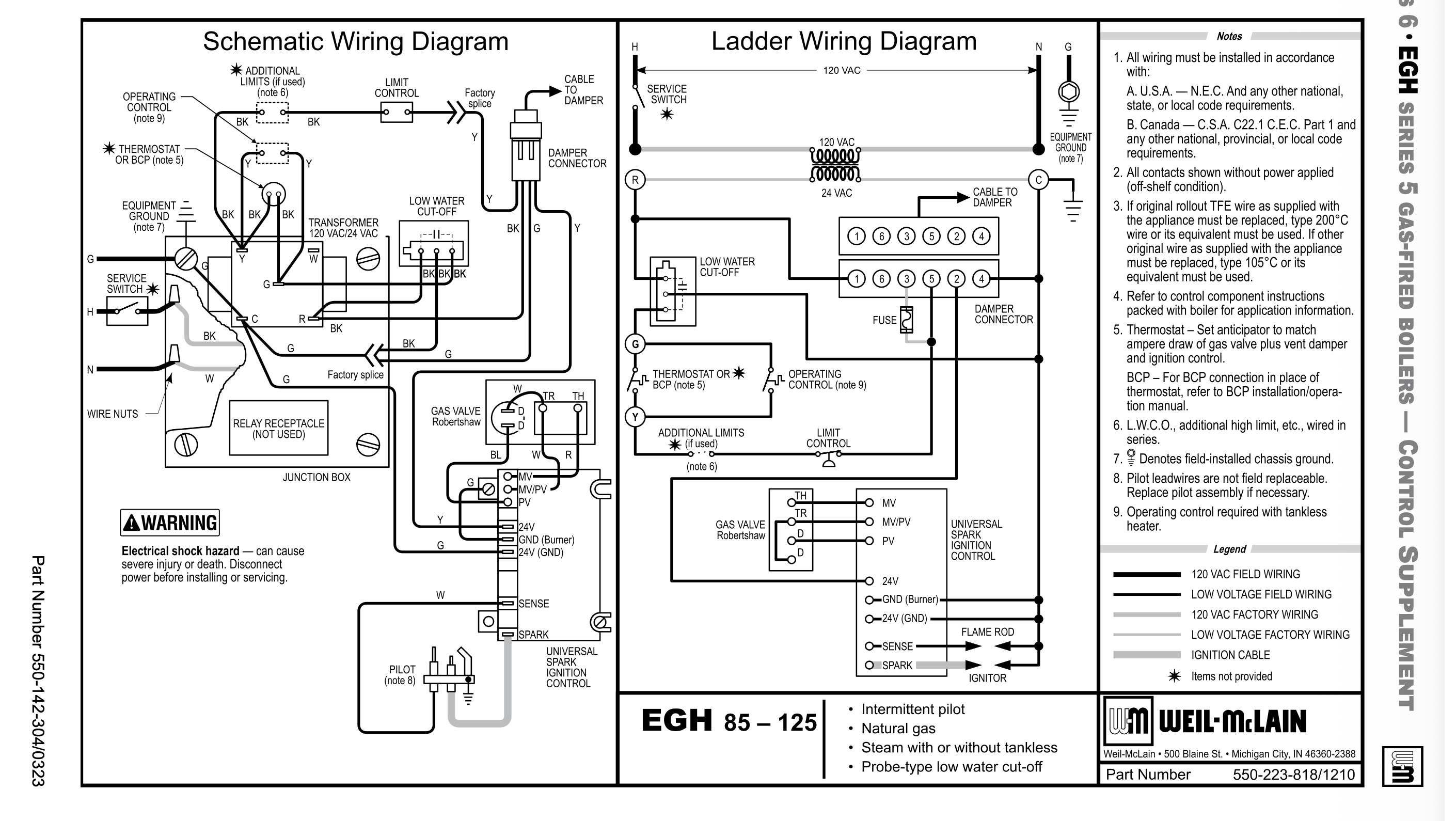
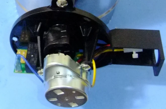
Weil-McLain EG/H: thermostat and pressuretrol shut the damper, but not the spill switch.

For troubleshooting purposes, I'm trying to explain to my guys that on a no-heat call the damper being open is the first indication there is a call for heat, but it will remain open if the spill switch is activated yet will close if the pressure is satisfied. The included wiring diagram does not support my claim. All the safeties and limits are before the end switch of the damper. Or am I reading this wrong? What goes on inside the damper has always been at the very limits of my electrical comprehension. Power to open, power to close? Whyyyyyy? Can't the damper just spring close like a zone valve?
Consulting & Troubleshooting
Heating in NYC or NJ.
Classes
Comments
-
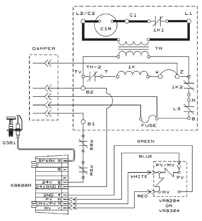
These always confused me as well and I am an electrician. Looking at the ladder diagram
Basically 4 wires to the damper:
- Constant hot 24v from transformer "R" Black wire to #1 on the damper
- 24 volt common from transformer "C" Green wire to #4 on damper
- #2 on damper yellow wire to 24v on ignition control (starts burner)
- yellow at damper. Starts at "R" red on transformer through limit and operating controls to damper #5
I have looked at the internal damper wiring. The way I think it works is:
thermostat and controls call for heat, this pulls in a relay (internal in the damper) to open the damper but it just operates the relay. The damper power comes from the "constant hot wire". When the call for heat ends or pressure control or LWCO opens the damper loses its "signal" and the internal relay drops out and the damper is driven closed also by the constant hot.
As for the damper position. The limits and thermostat circuit have to be closed for the damper to open. Once the damper opens the damper motor is stopped by the internal switches. Once the damper is open if a limit or stat opens the damper will drive closed.
But if something was wired into the "constant hot" and that opened the damper will stop wherever it is.
I don't see a spill switch on the diagram. If it was wired into the constant hot and it opens the damper can't move.
The confusing part is the hot from the thermostat and limits just operates the internal damper relay. The damper power comes from the constant hot.
Hope this helps. Maybe @EdTheHeaterMan or someone else who knows this better than I do will comment.
0 -
All depends on where the limits are wired into the circuit. If the spill switch trips it may be best practice to keep the damper open, spring close would not allow that.
The spill switch is on the control side of the damper on this one.
 National - U.S. Gas Boiler 45+ Years Old
Steam 300 SQ. FT. - EDR 347
One Pipe System0 -
To me an open damper just means the damper is open, with no guarantee of anything else.
Developing skills with reading the diagrams and use of a multimeter and tracing out the wires or the circuit path (with wiring diagrams or not) may be better for the troubleshooting process in the long run.
Assessing the state of the limits and controls should not take long and may be a quicker path to an accurate diagnosis than assuming an open damper means the same thing in every case.
National - U.S. Gas Boiler 45+ Years Old
Steam 300 SQ. FT. - EDR 347
One Pipe System0 -
In this case I believe with a tripped rollout or blocked vent safety limit, you may find the damper open with a call for heat. However if the 120 to 24 VAC transformer dies with the damper open, the damper will remain open. I would think learning the circuits the basic components and use of a multimeter may give more consistent troubleshooting results, but it is not for everyone.
 National - U.S. Gas Boiler 45+ Years Old
Steam 300 SQ. FT. - EDR 347
One Pipe System0 -
-
Yes, those diagrams were intentionally chosen and I thought the operation was kind of obvious, which is why I chose those diagrams. If not, thank you for the clarity. Which is why I basically suggested better education and troubleshooting technique and not base 'no heat' troubleshooting on whether the damper is found open or closed.
A damper found open may give you correct troubleshooting direction or it may not, it's just an open damper. IMO learning how to troubleshoot basic electrical circuits is much more valuable than the open or closed state of the damper.
National - U.S. Gas Boiler 45+ Years Old
Steam 300 SQ. FT. - EDR 347
One Pipe System0 -
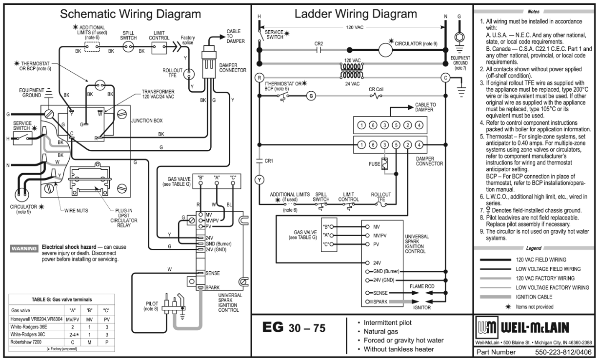
So here are two other variations. The first example a tripped Blocked Vent Switch will close the damper. A tripped Flame Rollout Switch would result in the damper staying open.
In this case a tripped Blocked Vent Switch (SSW) or a tripped Flame Rollout Switch (RSW) would result in the damper staying open.
 National - U.S. Gas Boiler 45+ Years Old
Steam 300 SQ. FT. - EDR 347
One Pipe System1 -
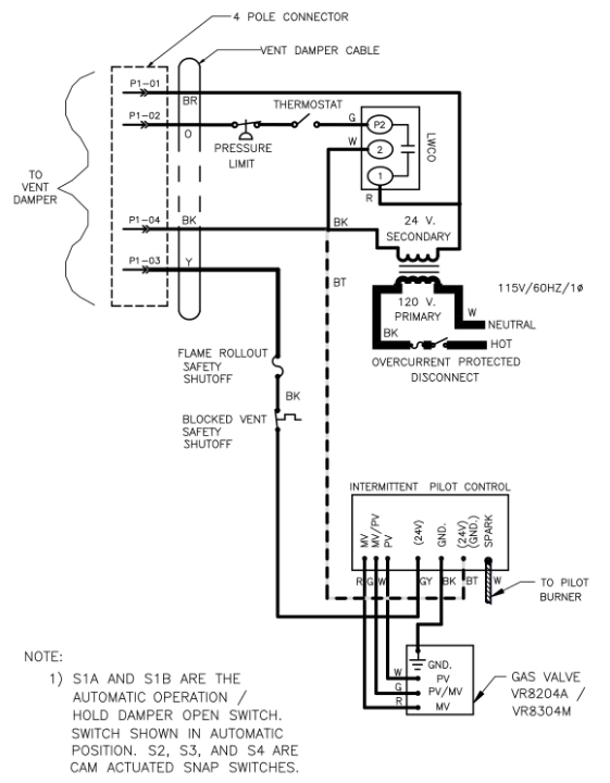
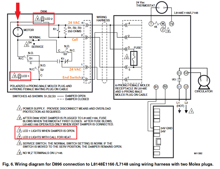
The best diagram I have on the internal of the auto vent damper, and this is from a long time ago (not the current Fields/Effikal version) is this one:
The motor stops at each 90° turn of the motor. 90° to open, 180° to closed, then 270° to open, then 360° = 0° to close. There is constant power needed to operate the motor to close the damper after the call for heat is satisfied. @EBEBRATT-Ed has the correct wiring description
- Constant hot 24v from transformer "R" Black wire to #1 on the damper
- 24 volt common from transformer "C" Green wire to #4 on damper
- #2 on damper yellow wire to 24v on ignition control (starts burner)
- yellow at damper. Starts at "R" red on transformer through limit and operating controls to damper #5
There is a 6 Pin Molex on the control that the damper is attached to in order to prevent Bubba from placing the jumper plug back on the control while there is a broken damper installed in the flue connector between the boiler and the chimney base. There is a fuse placed between pin #3 and #5 on the Molex mounted on the control. The factory installed jumper connects pin #2 and #3 in order to complete the “End Switch” circuit when a vent damper is not used. when a damper is connected the 6 pin has on more wire that @EBEBRATT-Ed did not include. the green wire (24v. hot or R) is connected to pin 4 and pin 3
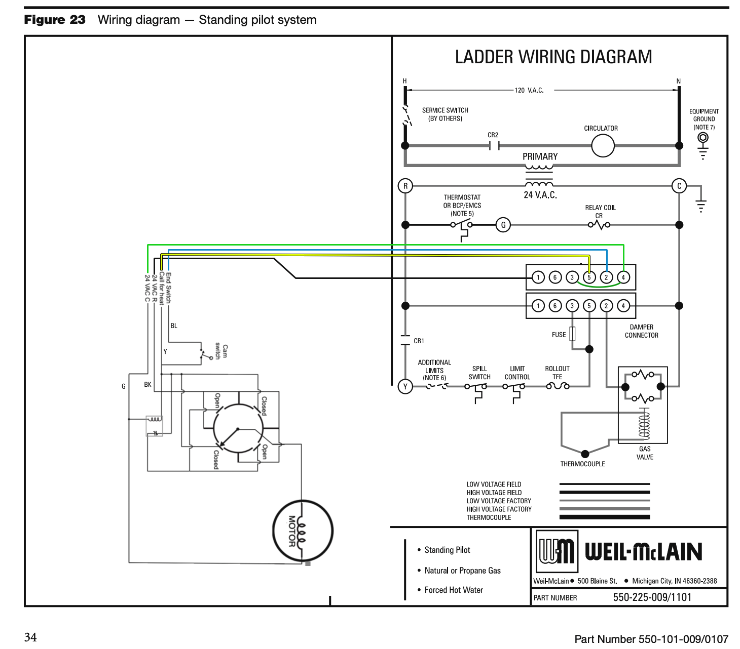
Imagine Bubba at the service call: This has happened more than once before this wiring design was made standard. No heat and the vent damper cam switch (end switch) is the problem. So, Bubba jumps the switch to get the burner to operate and locks the damper in the open position (because he is too lazy to remove the damper) and you have heat. Later someone sees that the damper is locked open and does you a favor by removing the bracket that is keeping the damper from closing in order lower your fuel bill and save you money.
The next call for heat the damper gets stuck closed but the cam switch is jumped and the burner operates with a closed damper. The next day there is a big news story about carbon monoxide poisoning. In the 1970’s this was not just a one off story but something that happened enough times to cause a new standard wiring design using that special connector cord with a 4 pin on one end and a 6 pin on the other end Here is how that works.
- No damper = jumper from 2 to 3
- Add a damper and the first time the damper opens power gets sent to 5 and 3
- 5 powers the burner circuit and 3 gets a direct short to the transformer and the fuse blows between 5 and 3
- Now the jumper from 2 to 3 will no longer work on that control
Now if the factory installed "No Damper" jumper is put back in the control, after a damper has been installed and wired in, it will no longer work since the fuse between 5 and 3 is blown. This keeps Bubba from just putting the jumper on the control to get heat without doing some real serious rewiring and maybe even removing the damper from the flue connector pipe.
I hope this is as clear as mud now @JohnNY
I need to add this one to my "How Do I connect This Wire?"
Edward Young Retired
After you make that expensive repair and you still have the same problem, What will you check next?
 1
1 -
As far as your original Query "For troubleshooting purposes, I'm trying to explain to my guys that on a no-heat call the damper being open is the first indication there is a call for heat, but it will remain open if the spill switch is activated yet will close if the pressure is satisfied. The included wiring diagram does not support my claim. All the safeties and limits are before the end switch of the damper. Or am I reading this wrong? What goes on inside the damper has always been at the very limits of my electrical comprehension. Power to open, power to close? Whyyyyyy? Can't the damper just spring close like a zone valve?"
I might suggest that the Roll Out Fuse and the Spill Switch are not specifically noted in the Schematic Wiring Diagram or the Ladder Diagram. Look closely at the Roll Out Switch actual wiring on the appliance to see if that was added by the installer to break the circuit from the #5 on the damper plug to the 24V on the ignition control.
Edward Young Retired
After you make that expensive repair and you still have the same problem, What will you check next?
0 -
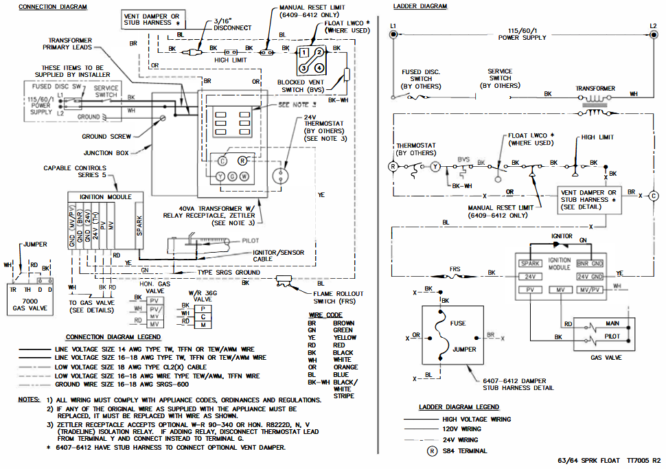
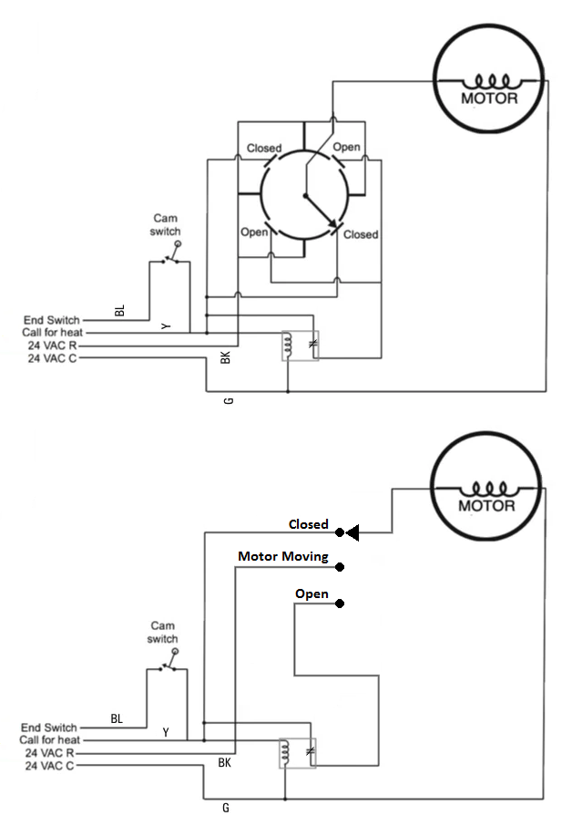
Page #6 shows damper internal wiring. I don't see this damper stopping every 90 degrees. The "constant power" drives the damper open or closed. Weather it opens or closes depends on if the limit circuit is calling or not calling.
So basically, anything in the limit circuit wire #5 on the damper that opens will cause the damper to close.
If something is wired between #2 on the damper and the ignition control opens the damper remains open.
I think part of the confusion is that the 24 volts to terminal #1 on the damper is the power to drive the damper. Constant power
The limit circuit to terminal #5 pulls in or drops out the spdt relay in the damper to open or close the damper
The other thing (at least with the Honeywell) is that when the boiler is firing and the damper is open it just sits there with no power to the motor.
@EdTheHeaterMan your internal diagram is giving me a migraine. Not understanding that one.
Guess different brand of dampers have different internal wiring but work with the same 4 wires.
constant power
power to ignition control
common
limit circuit.
 1
1 -
I'm not sure those two schematics are for the same damper, but in any case that synchronous motor isn't likely to be reversable. It'll drive open & closed going the same direction each time.
I'm not sure why they did it that way because now they have to be clever to make it work—and clever is rarely simple to understand or diagnose.
0 -
And yet another lesson to learn. You can't trust the documentation 100 %.
In this example both LEDs would be on at the same time since they are wired in series. I added the apparent missing connection.
 National - U.S. Gas Boiler 45+ Years Old
Steam 300 SQ. FT. - EDR 347
One Pipe System0 -
Synchronous motors like that will run in either direction. Often if needed there is a mechanical jamming mechanism to make them run (start) in only one direction (like an old clock) or if needed reverse and start in the other direction.
National - U.S. Gas Boiler 45+ Years Old
Steam 300 SQ. FT. - EDR 347
One Pipe System0 -
I stand corrected.
But the dampers I've seen (full disclosure: not many) only turn in one direction.
0 -
With @EdTheHeaterMan damper example it may be a switch with segments like a wafer switch or segmented slip rings.
With @EBEBRATT-Ed damper example the micro-switches use a cam assembly that rotates with the damper plate to monitor its position.
National - U.S. Gas Boiler 45+ Years Old
Steam 300 SQ. FT. - EDR 347
One Pipe System0 -
All I am saying is it could be done either way.
National - U.S. Gas Boiler 45+ Years Old
Steam 300 SQ. FT. - EDR 347
One Pipe System0 -
With the upper original schematic the motor control switch that changes state by the movement of the motor and indexed to the damper plate can be simplified and drawn like this in the lower redrawn schematic. Although the switch in the simplified drawing does not show the 90 degree damper plate indexing.
 National - U.S. Gas Boiler 45+ Years Old
Steam 300 SQ. FT. - EDR 347
One Pipe System0 -
Seems that both dampers work off the same external wiring. 1 constant hot, 1 common, 1 call for heat and 1 to power ignition so I guess the dampers could be interchangeable. Don't know if the plugs match.
I noticed the LEds in series as well.
 1
1 -
@109A_5 I saw some flaw in the wiring logic so I fixed it. That first old diagram I copied was never proofed to see if it works… it was just a concept drawing from taking apart some old damper that is no longer made. It took a long minute to find it but I knew it was on an old computer somewhere
@EBEBRATT-Ed said: @EdTheHeaterMan your internal diagram is giving me a migraine. Not understanding that one.
Take each circuit one at a time if you want to understand it.
Everything in Red is powered and the blue is the return path to the transformer. The purple Is the path from the rotary switch arm to the hot side of the damper motor.
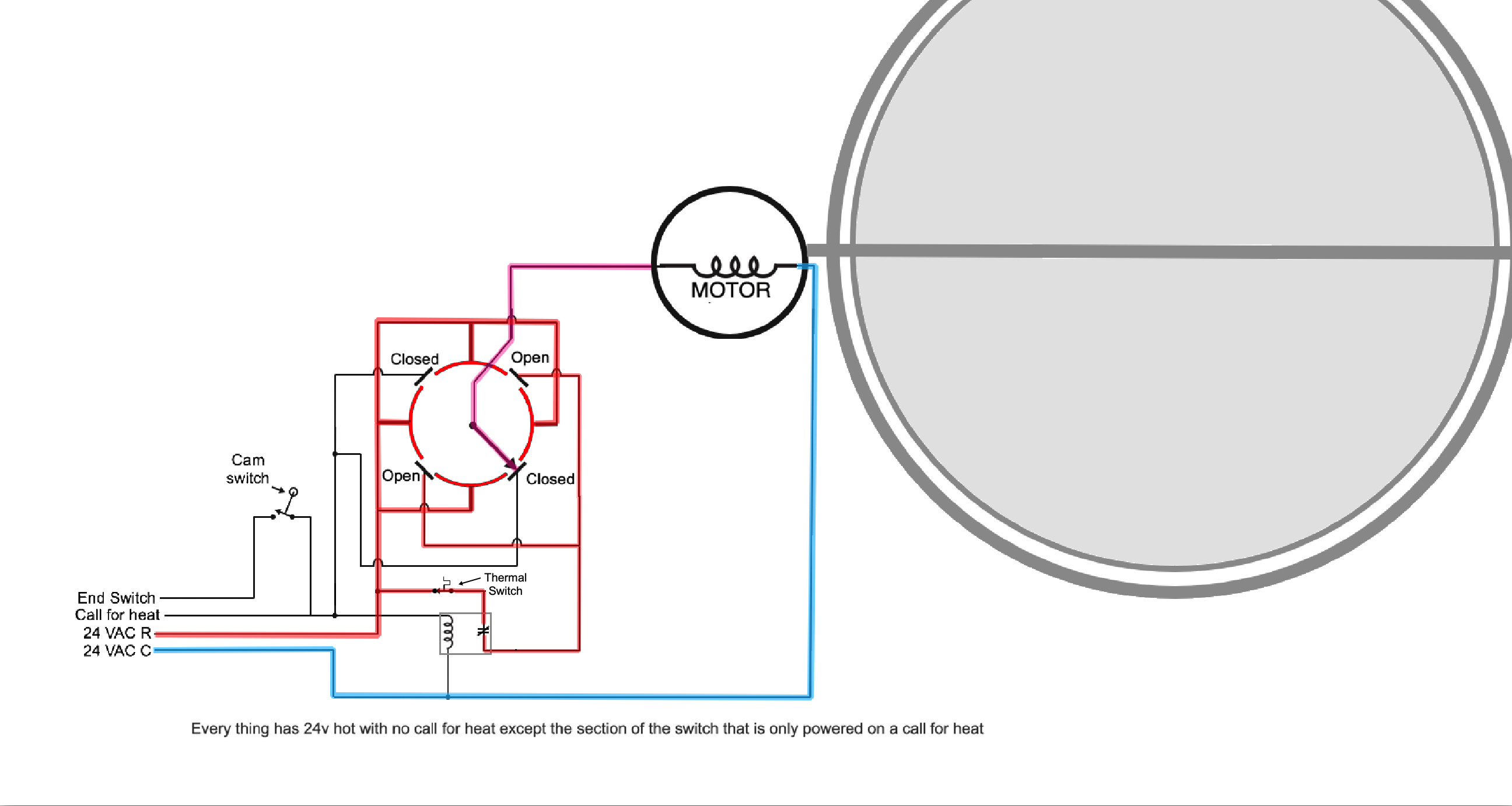
The switch arm in the closed position has no power until there is a call for heat
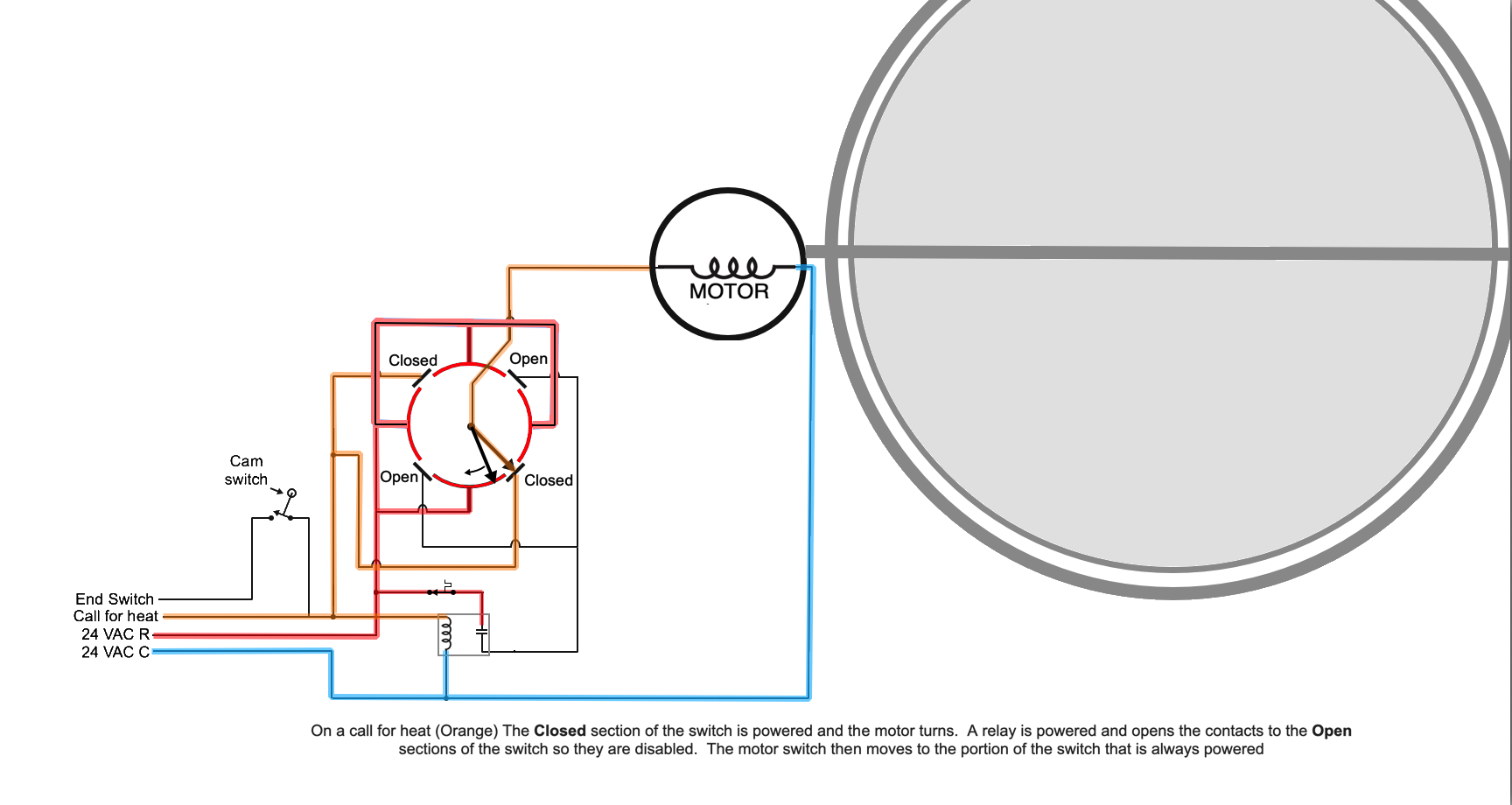
That call for heat causes three things to happen (See Orange wires). The Closed contacts get power to start the motor. A relay coil causes the power to the Open section to the rotary switch to lose power and the motor then reaches the “Always Hot” portion of the rotary switch so it continues to operate until it is completely open.

When the motor reaches the full open position the motor stops since there is no power to the Open contacts on the rotary switch. Also the Cam Switch (End switch) closes sending power to the burner circuit (Green wire).
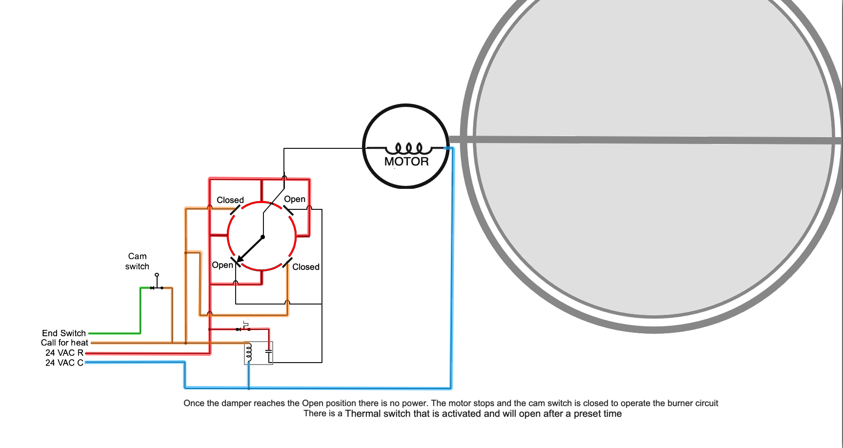
The burner operates safely with the damper open. Eventually the call for heat or a limit stops the burner.
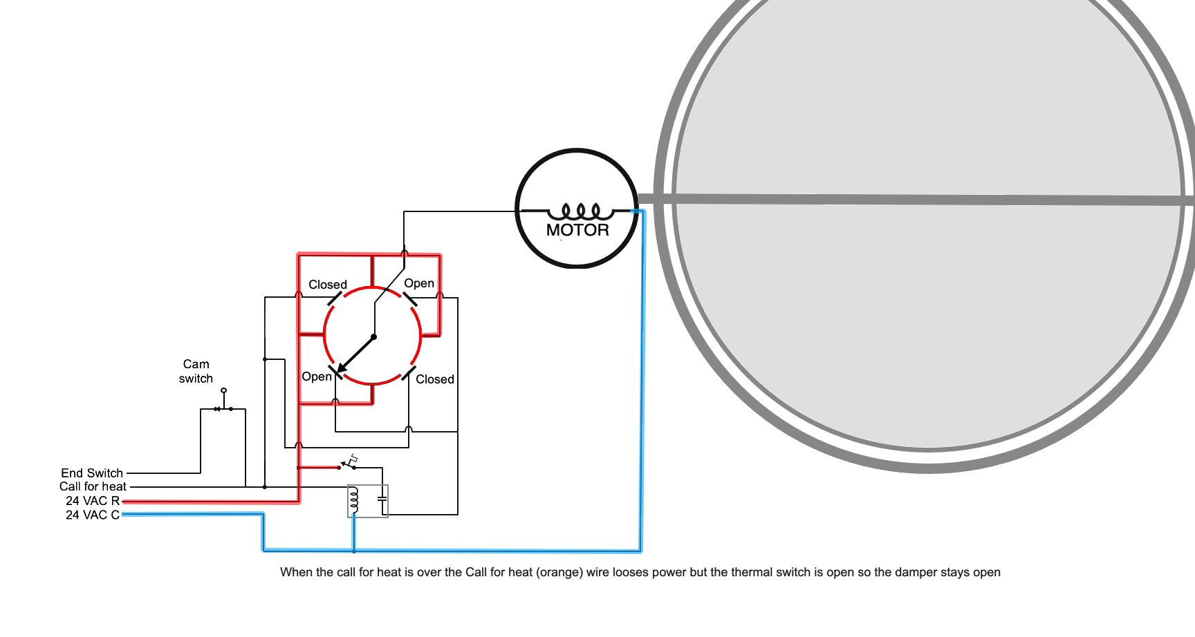
The orange call for heat looses power and the green to the burner looses power but the thermal switch may keep the damper open for a time in order to clear out the byproducts of combustion from the boiler or furnace.
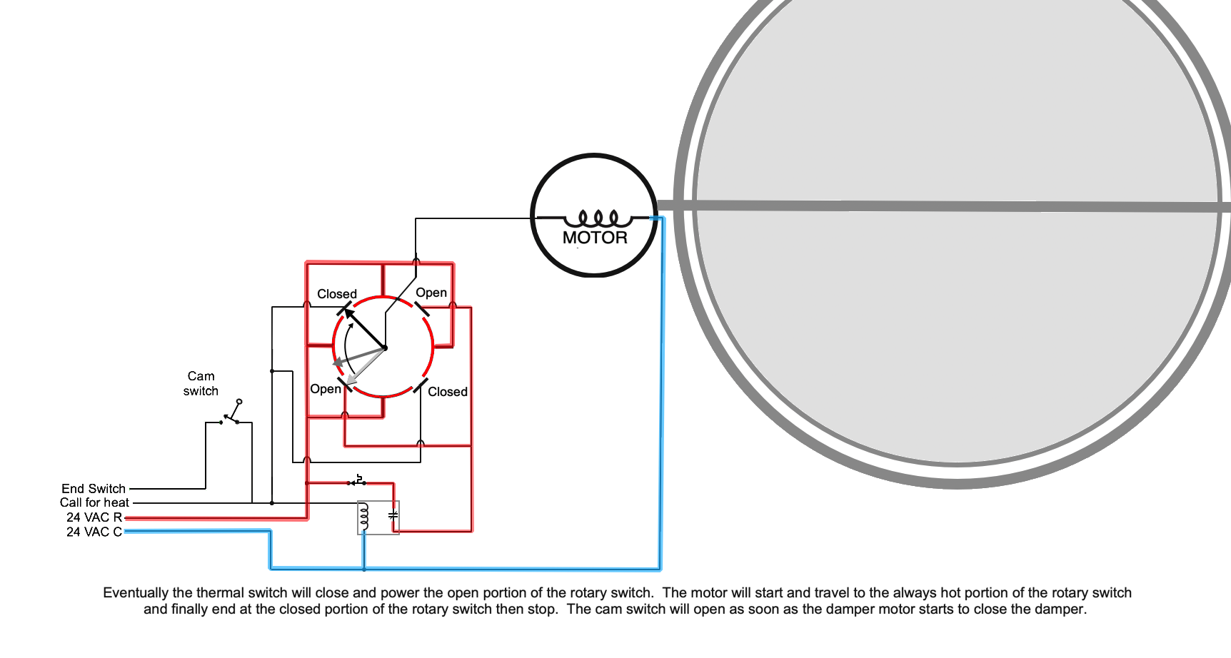
Eventually the thermal switch will close and power the open portion of the rotary switch. The motor will start and travel to the always hot portion of the rotary switch and finally end at the closed portion of the rotary switch then stop. The cam switch will open as soon as the damper motor starts to close the damper.
Edward Young Retired
After you make that expensive repair and you still have the same problem, What will you check next?
0 -
@EBEBRATT -Ed. I didn't intend to give you more homework, but it is nice to know what might be happening inside those mystery motor boxes. The Field Controls dampers have circuit boards and can accomplish the rotary switch function electronically. Now that stuff is a mystery to me.
Edward Young Retired
After you make that expensive repair and you still have the same problem, What will you check next?
0 -
@EdTheHeaterMan My eyes aren't so good but the first diagram you posted looked like the relay contacts were NO instead of NC. I guess thats what threw me off.
0 -
I looked at the Field damper. They just give you external wiring, nothing internal. I guess they don't wan't us to know.
 3
3 -
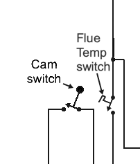
OK @EdTheHeaterMan just conceptual, looks like it would work. Yeah the Flue Temp Switch is in a non-helpful place.
I think you would find the circuit board version is pretty much the same as the version that @EBEBRATT-Ed posted, just built different but electrically very similar.
 National - U.S. Gas Boiler 45+ Years Old
Steam 300 SQ. FT. - EDR 347
One Pipe System0 -
-
They probably were NO on the first diagram. There were 2 other mistakes too. I fixed them in the final diagrams.
In the 1980s and 90s there was this toilet paper (janitorial supplies) salesman that would try to sell anything to make a buck and he tried to cash in on the automatic vent damper craze They were called Energy Stack Vent, and he needed someone that understood how to fix the mistakes his installers were making. I probably put in over 100 of them and fixed 200 more.
He would buy the vent damper from some manufacturer for about $60. and pay an installer $85. to install it. He was selling them for $600.00 and telling the customer that it would pay for itself in 2 to 3 years. The vent damper company went out of business because they made too many people sick with CO. But the guy made a small fortune for about 3 to 5 years selling hundreds of them. That is the piece of junk I took apart to get that diagram.
I like the Honeywell D896 paperwork you were able to find. Thanks for that.
Edward Young Retired
After you make that expensive repair and you still have the same problem, What will you check next?
0 -
I know on oil in the late 70s (embargo) there were two stack dampers for oil. I think the "Flair Stack Pak" was one. I can't remember who made the other one.
Oil prices went up and a lot of people wanted two things:
Stack dampers
add an extra 275 so they could "save " on oil and fill up in the summer.
Then by 1980 or so it was gas conversions.
I remember when I got out of school in 73' they said New England was 80% heated by oil. Gas was like 16% and electric, wood was the rest.
I wonder what it is now?
I had to dig a bit for the D896. I guess Honeywell isn't making dampers anymore.
0 -
You(s) absolutely did, but in a good way. Sometimes it's the half-step backward that powers the big leap forward.
You guys are fantastic.
Thanks for taking the time to engage my post. I was hoping to create some kind of visual/mental troubleshooting flow chart but I see that the burner circuit wiring is always going to be model specific where there is a damper involved. We install a lot of Weil-McLain EG and CG products and it looks like the location of the safeties within the circuit cannot be reliably committed to memory. OR at least not THIS memory. Add to this, changes made in the field that deviate from the original wiring schematic and who-jumped-out-what last season to get the thing running again…
So, maybe the takeaway here is there just ain't no shortcuts, man.
Now to trace and retrace that internal damper wiring diagram again…
Happy holidays to all.-John Cataneo
Contact John "JohnNY" Cataneo, NYC Master Plumber, Lic 1784
Consulting & Troubleshooting
Heating in NYC or NJ.
Classes1

Categories
- All Categories
- 87.6K THE MAIN WALL
- 3.3K A-C, Heat Pumps & Refrigeration
- 59 Biomass
- 429 Carbon Monoxide Awareness
- 124 Chimneys & Flues
- 2.2K Domestic Hot Water
- 5.9K Gas Heating
- 119 Geothermal
- 168 Indoor-Air Quality
- 3.8K Oil Heating
- 78 Pipe Deterioration
- 1K Plumbing
- 6.6K Radiant Heating
- 394 Solar
- 15.9K Strictly Steam
- 3.5K Thermostats and Controls
- 56 Water Quality
- 50 Industry Classes
- 50 Job Opportunities
- 18 Recall Announcements