oops!!!!

last night I was dismantling my boiler to clean out the mice, crap, etc, (yearly ritual) & I now have 3 wires that need a home. It's a national from 1949 & came with the house. We've been here 7 years now & i must admit we've had very few problems with it , ( till last night ) . Normally i put a piece of tape ( with some of my home made short hand on it ) so i know where they belong when it's time to reassemble. Well, i had the tape ready with my short hand already applied & forgot to attach it untill it was too late . Maintenance on this unit is 250$ just to pay for their gas to pull in my driveway , so i thought " what the hell " i'll buy myself some gas & maybe take a vacation or two & see if i , or you can fix it .
Comments
-
Take a photo of the burner control to which the wires were attached… and post that. And then figure out where the other end of each wire is and what it attaches to and post that. Someone will figure it out ( @EdTheHeaterMan is a genius at that!)
Br. Jamie, osb
Building superintendent/caretaker, 7200 sq. ft. historic house museum with dependencies in New England

 3
3 -
@Brian61 The wires are easy for some to figure out, and can be a mystery to others. Can you take some photos of what the wires were connected to. Short of that, it will be difficult to determine. (Ha Ha! See how I added an electric Pun "Short of that")
Can you tell me if this is on an Oil Fired boiler, or a Gas Fired boiler?
Edward Young Retired
After you make that expensive repair and you still have the same problem, What will you check next?
 1
1 -
Sounds like gas if you clean out mice by the burner.
0 -
heres your pic:s, technology aint my thing the photo poiuytf theres 3 little bolts the wires go on those & when i teted them none of them were hot
its a gas burner
0 -
when i tested the wires they wer'nt hot
0 -
the photo 187 is where the wire starts from then goes to photo 185 , 2 of the wires get connected there ( i know where they go ) & then on to that little silver box where all 3 get connected
0 -
can you take some pictures of the burner, especially of the pilot assembly and the wires to that if any? I think it is a millivolt valve so the controls are switching the current from the thermopile/pilot generator in the pilot flame.
EDIT:
Looking some more, I don't think it is millivolt but the wire must make a stop up in the ceiling somewhere between the boiler and the transformer to connect to the thermostat.
0 -
From the looks of the pictures there are several issues that MUST be addressed.
You really need someone that is qualified to do it.
0 -
My brother in-law lives 16 miles from us. He's lived there about 10 years. We've been there too many times to count, but my wife still needs to put his address in the navi. So I feel you. But it's probably time for professional service if its been seven years. There's more to a heat maintenance than cleaning mouse marbles.
0 -
you know what a professional is ? ,,,, someone from out of town,,,,,,,,,,,,,, yea i know your right , but like Waylon says " i've always been crazy it's kept me from goin insane ( : i'll let ya'll know how your advice worked . damn, ya'll didn't even try,,,,,,,,,,,
0 -
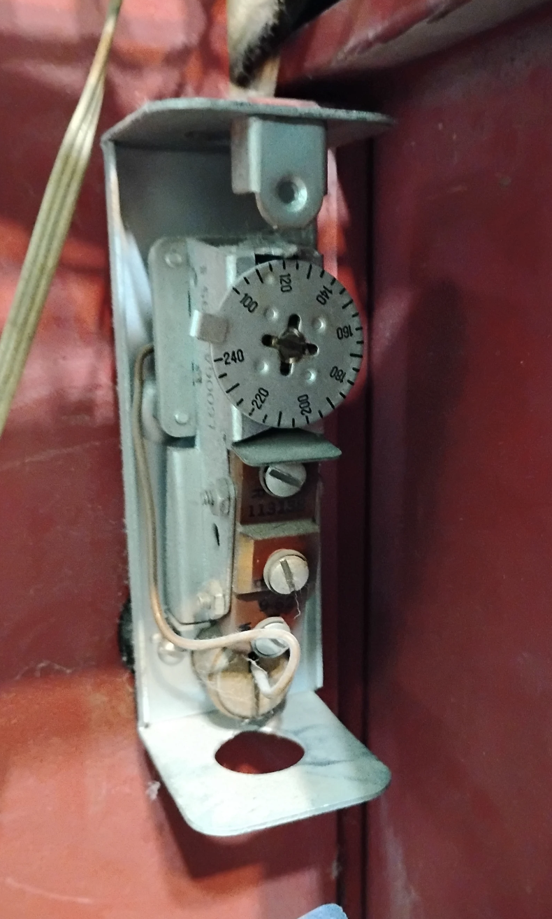
Are there any more controls like this one? this is possibly the High Limit control but the setting is at 120° which in my mind is too low to be the HI limit
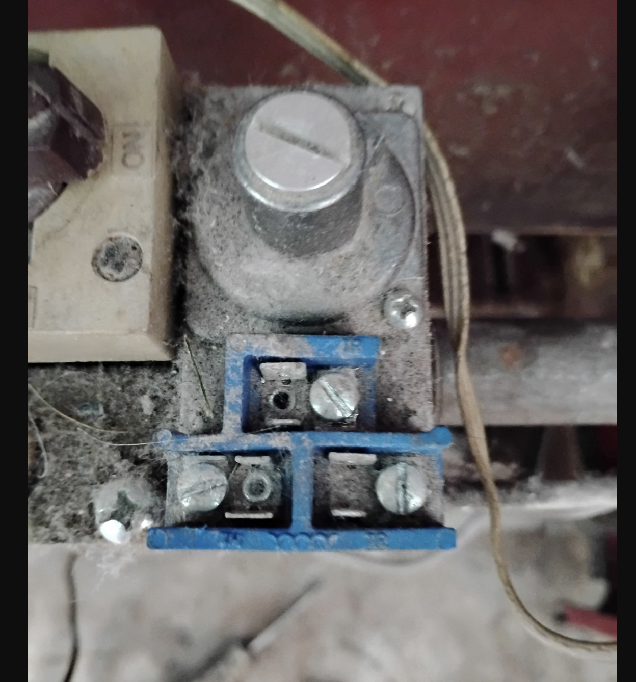
This photo indicates that your heating boiler is located near your clothes dryer, and that clothes dryer vent is allowing lots of lint into the boiler room area. All the telltale dust on the gas valve tells me that there is most likely dust on the actual burners inside the fire compartment, and the combustion air openings of the burners. That dust can lead to insufficient combustion air and incomplete combustion. That can lead to the boiler heat exchanger getting a build up of soot and carbon that will cause more problems that you do not want to deal with, some day this winter.
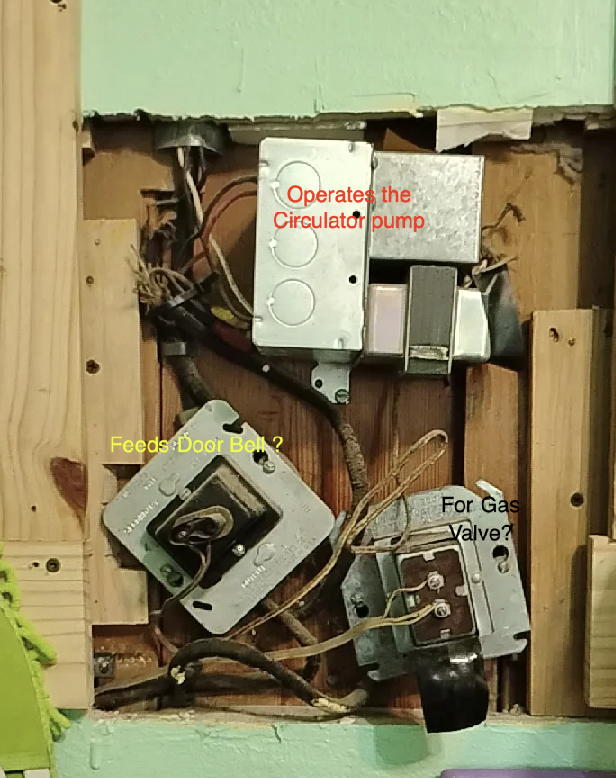
This shows that you have three 24 volt transformers. You only need one to operate that heating boiler. Without seeing the bigger picture I have to ask how many thermostats you have? That may explain the reason for more than one transformer.
But getting back to your wiring problem, If you have only one thermostat for the entire home, then at least one of those transformers is not for the heating boiler. So I am guessing that the door bell is connected to the transformer on the left That leaves the upper transformer with a relay, to operate the circulator pump, and the other transformer on the lower right looks like it has the same 3 wire that is near the high limit control in the top picture.
Now let's just say that you get a professional to come to make sure the 1949 boiler is operating safely and properly and that professional is not experienced on older model equipment. They might tell you that you need new equipment (and they would probably be right when it comes to operating cost) by telling you that this old stuff is unsafe. (that would be wrong information) and you didn't mind the "operating cost" gas bill which you feel is very affordable, and therefore no amount of fuel savings will justify the cost of a replacement boiler. You will need to know how to put the wires back…
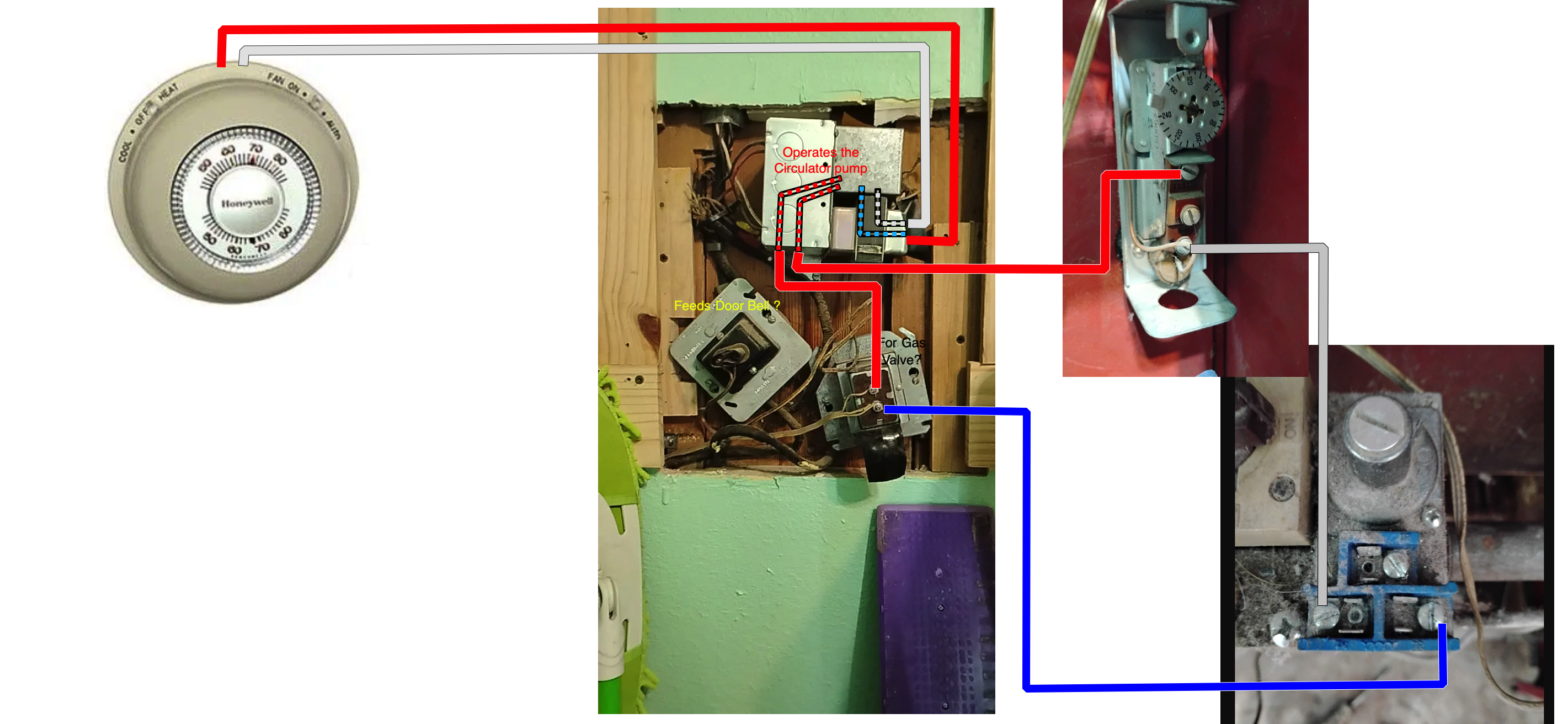
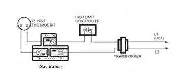
I am only guessing at this point as to what you might have… but this is a safe wiring diagram that will shut off the gas burner in the event the water in the boiler gets hotter that the High Limit Setting. I would like to tell you the put the red wire here, and the green wire there but you only have gray wires, so I have placed colors on the diagram for clarity, but electric is color blind and will travel thru any color wire. I have made the assumption that the top transformer/relay is connected to the thermostat. When the thermostat calls for heat, the relay in the silver box will connect 120 VAC to operate the circulator pump. There will also be a connection in that same relay using low voltage (24 volts) to make the gas valve operate the burners.
This is most likely where you have the three disconnected wires. I have indicated that one of the three wires is Red and connects from the transformer to the R terminal on the aquastat. The W on the Aquastat will get connected to the TH on the gas valve indicated by the white wire in the drawing. Then the TR on the gas valve will get connected to the transformer indicated by the blue wire on the drawing.
I hope this helps. And I really recommend that you call a professional to check your boiler. It is probably in need of some professional maintenance. Hopefully you will get someone experienced that will actually do a good job for you.
Mr. EdBy the way, when I did gas boiler maintenance I never found it necessary to remove the wires you removed. This might tell you something…
Edward Young Retired
After you make that expensive repair and you still have the same problem, What will you check next?
 2
2 -
Pictures with the available wires at each device location may help. A circuit is a loop, not sure if this wiring diagram will help you. I'll try to find one with better quality.
 National - U.S. Gas Boiler 45+ Years Old
Steam 300 SQ. FT. - EDR 347
One Pipe System0 -
I would think it could be wired so the wiring would not be in the way to do your maintenance. So no wiring need be disconnected for basic maintenance.
National - U.S. Gas Boiler 45+ Years Old
Steam 300 SQ. FT. - EDR 347
One Pipe System1 -
that's probably one where you have to pull the gas valve to pull the burners.
0 -
Seems like the OP isn't happy.
If I understood the 3 wire aqustat was hooked up on all three terminals so that would be low limit and circulator. Fan relay to run circ.
Could be an old non-integrated system with a tankless coil. Circ relay pulled in by T stat through the fan center relay when circ control is made. Other switch on aqustat maintains water temp by firing burner.
S/B a high limit in the picture as well.
1 -
That is why I asked if there were any more aquastats, and if there are any more thermostats. with the limited information given here, I can only speculate that there is one aquastat and one thermostat.
Edward Young Retired
After you make that expensive repair and you still have the same problem, What will you check next?
0 -
Maybe… But there is always polarized or indexed (if needed) connectors to make things easy.
And the wires were removed from the limit also.
National - U.S. Gas Boiler 45+ Years Old
Steam 300 SQ. FT. - EDR 347
One Pipe System0 -
Bottom line is we can't help without enough information.
1 -
Ed ?
0 -
you up yet ?
 1
1


Categories
- All Categories
- 87.6K THE MAIN WALL
- 3.3K A-C, Heat Pumps & Refrigeration
- 59 Biomass
- 429 Carbon Monoxide Awareness
- 124 Chimneys & Flues
- 2.2K Domestic Hot Water
- 5.9K Gas Heating
- 119 Geothermal
- 168 Indoor-Air Quality
- 3.8K Oil Heating
- 78 Pipe Deterioration
- 1K Plumbing
- 6.6K Radiant Heating
- 394 Solar
- 16K Strictly Steam
- 3.5K Thermostats and Controls
- 56 Water Quality
- 51 Industry Classes
- 50 Job Opportunities
- 18 Recall Announcements