using pex tees in hydronic hot water heat system

Hello, I was in a 9 unit apartment building basement that had some hot water feed and returns using multiple tees in the system. Most apartments complain that some baseboards don't get hot at all. The returns are all individually piped into one manifold but no individual shutoffs or purge valves on each line. The one main shutoff is after the manifold before entering into the furnace. The one circulator is on the return line.
The 9 feed lines come out of one main feed manifold and each line has a shutoff.
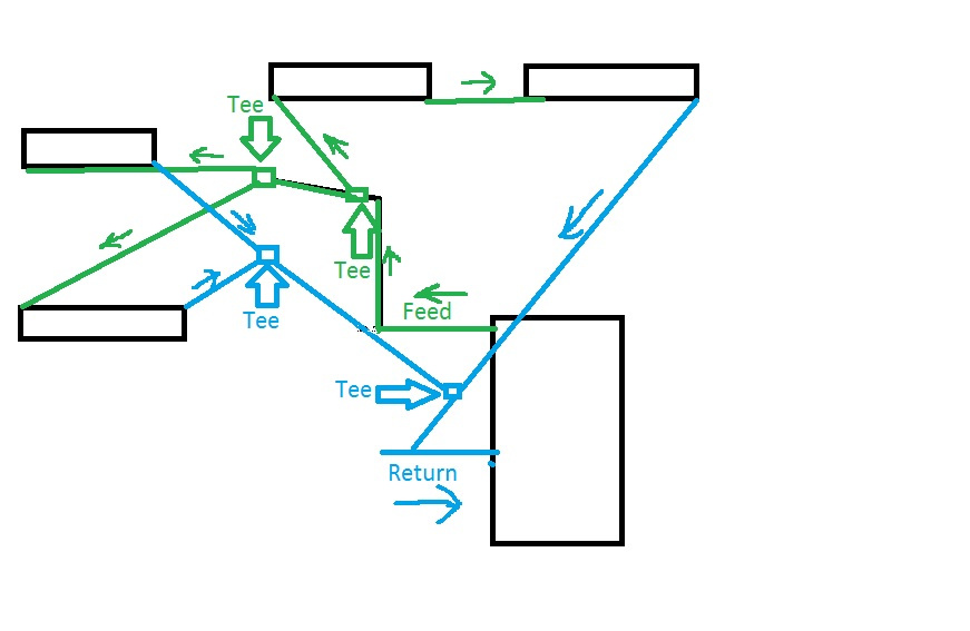
The question I have is the use of so many tees in the feed and returns in the loop system. Is this a good practice? I have enclosed a quick drawing of how one apartment is set up…keep in mind that the feed, baseboards and return lines are much more spread out than the picture shows. It is just for a rough idea how this whole system is set up.
Comments
-
The use of tees cannot be avoided unless the radiation is piped in a series loop which is only used for smaller jobs. Also with a series loop the baseboard footage installed needs to be adjusted because of the decreasing water temperature.
Sounds like you may have air trapped in some radiation or other issues.

 3
3 -
yeah for sure trapped air is most likely the culprit, what I feel may help is since only the feeds have each a shutoff valve but all 9 returns do not have individual shutoff valves …put a shutoff valve on each return line along with a purge valve would help isolate each apartment when trying to remove air. Does this sound like a better way to help isolate each apartment? As I stated above , the 9 returns come into the return manifold and then below the manifold is a shutoff and purge valve right before entering into the boiler…
0 -
How big are the mains? how big is the boiler? what is the actual heat loss of the building? how big are the emitters. Tees are fine if used properly but the main needs to be big enough to carry the heat.
0 -
Valentino,
You may benefit from piping the emmitters using reverse return. Also, we usually connect tees in a 2 pipe system with the branch connections horizontal.
0 -
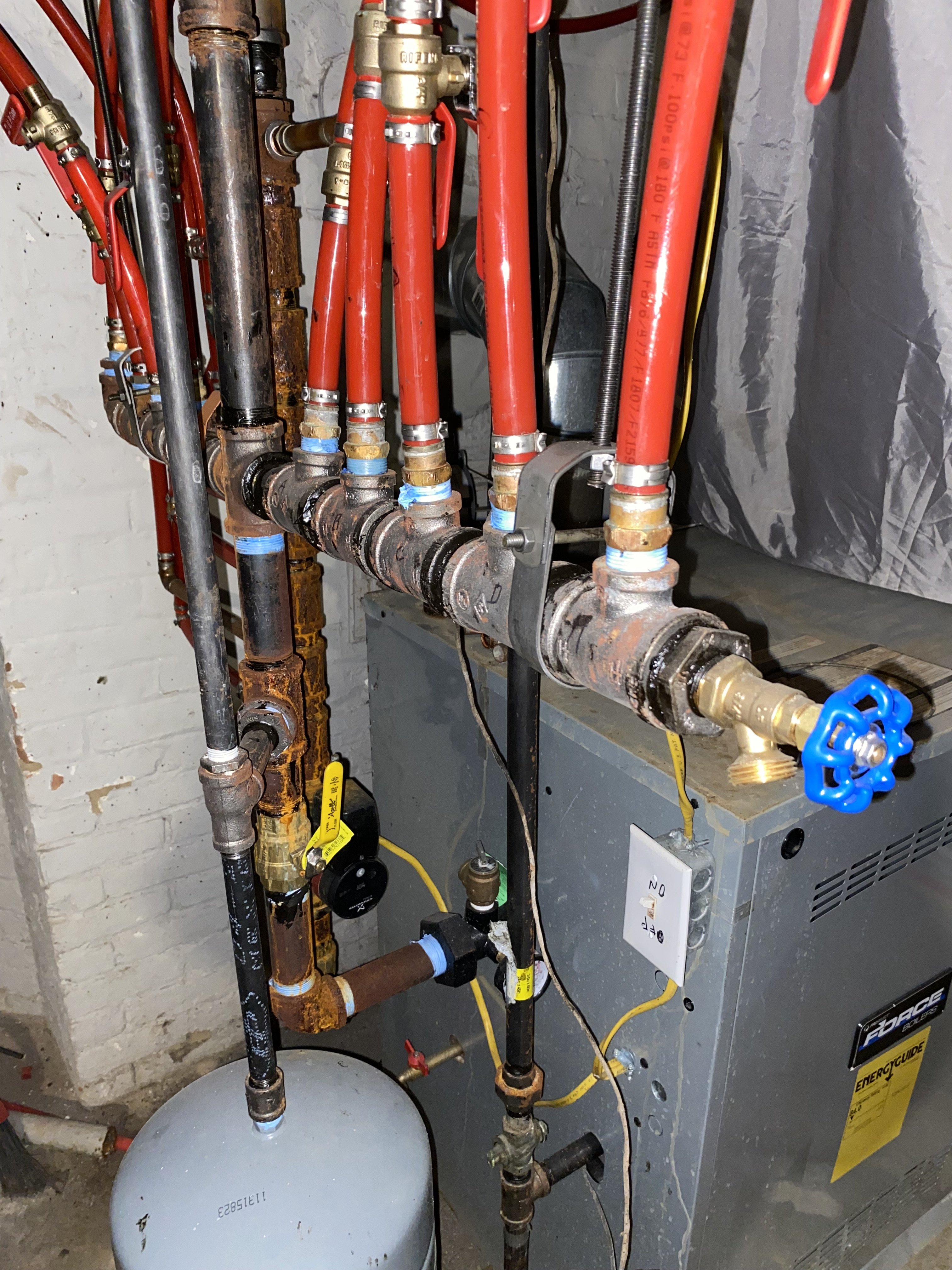
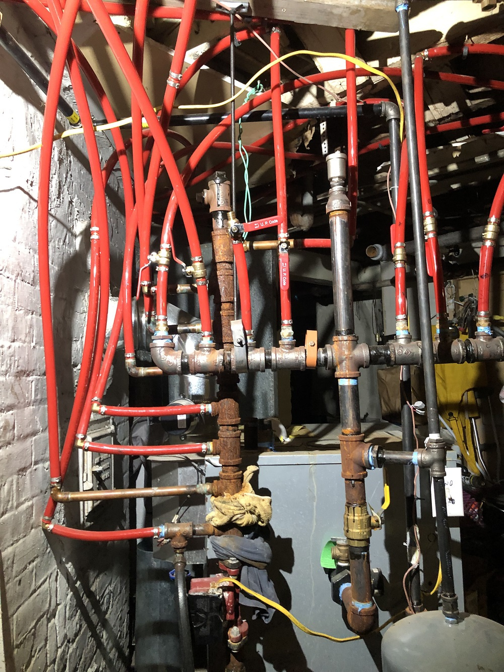
I will get some more pics tomorrow but here is the feed manifold,as you can see the return main stack leaks , I believe it is 180,000 btu, all apartments have single pane windows so a lot of heat loss…the apartment building is over 100 years old and I have been redoing plumbing and electrical work in the building for a while but did not do any work on the boiler ….
 0
0 -
-
It is very sloppy but should work if they did their math right…
0 -
yes the math is most important, without using a complicated heat loss calculation the 9 unit is about 8,600 sq feet and the boiler is 180,000 btu …the large windows are old and single pane so that alone is a huge factor …the 3rd floor has one apartment with no heat in it yet and they want to see if it can be added to the same boiler. I told them that is way too much already on the boiler…
0 -
you don't know that if you haven't done a heat loss calculation. the loss is only on the outside. is the 180,000 btu/hr input or output? Even the best windows are a bit worse than the worst solid wall so windows are more about how much area they are and how good the weatherstripping is. a modern house with a wall of glass of the best windows is going to be far more lossy than an old house with 100 year old windows without storms if they are in decent shape.
 2
2 -
you need about 18 gpm to move 180,000 btu/hr, assuming that is the output, so your header needs to be a minimum of 1.5" to move that much water to move that much heat. If that is the input you need about 14 gpm and could use 1.25" pipe for the headers.
0 -
piped like your drawing you will need some balance valves. Even a ball valve on each group would help balance the various loops
Did it ever work adequately?
Bob "hot rod" Rohr
trainer for Caleffi NA
Living the hydronic dream0 -
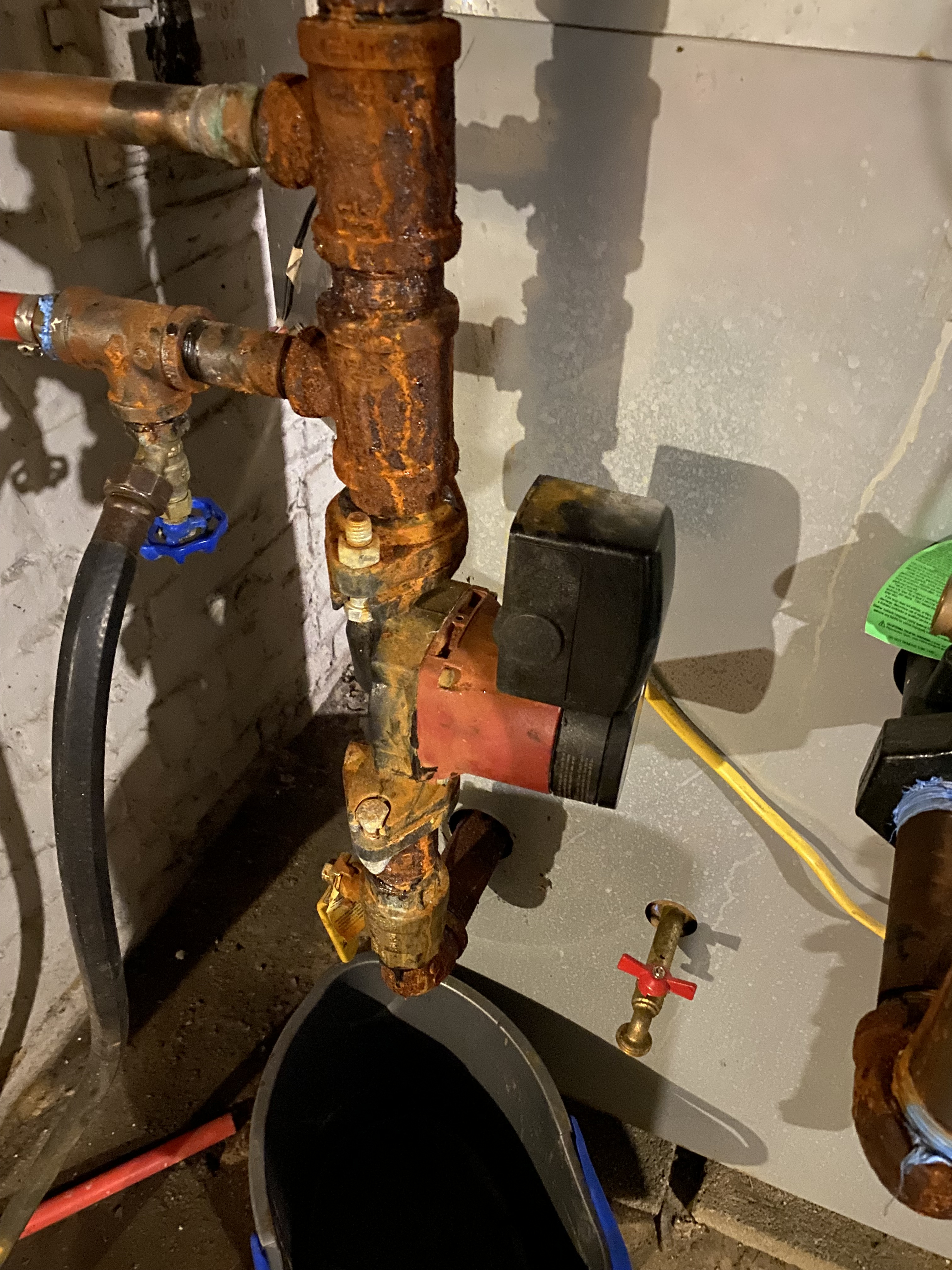
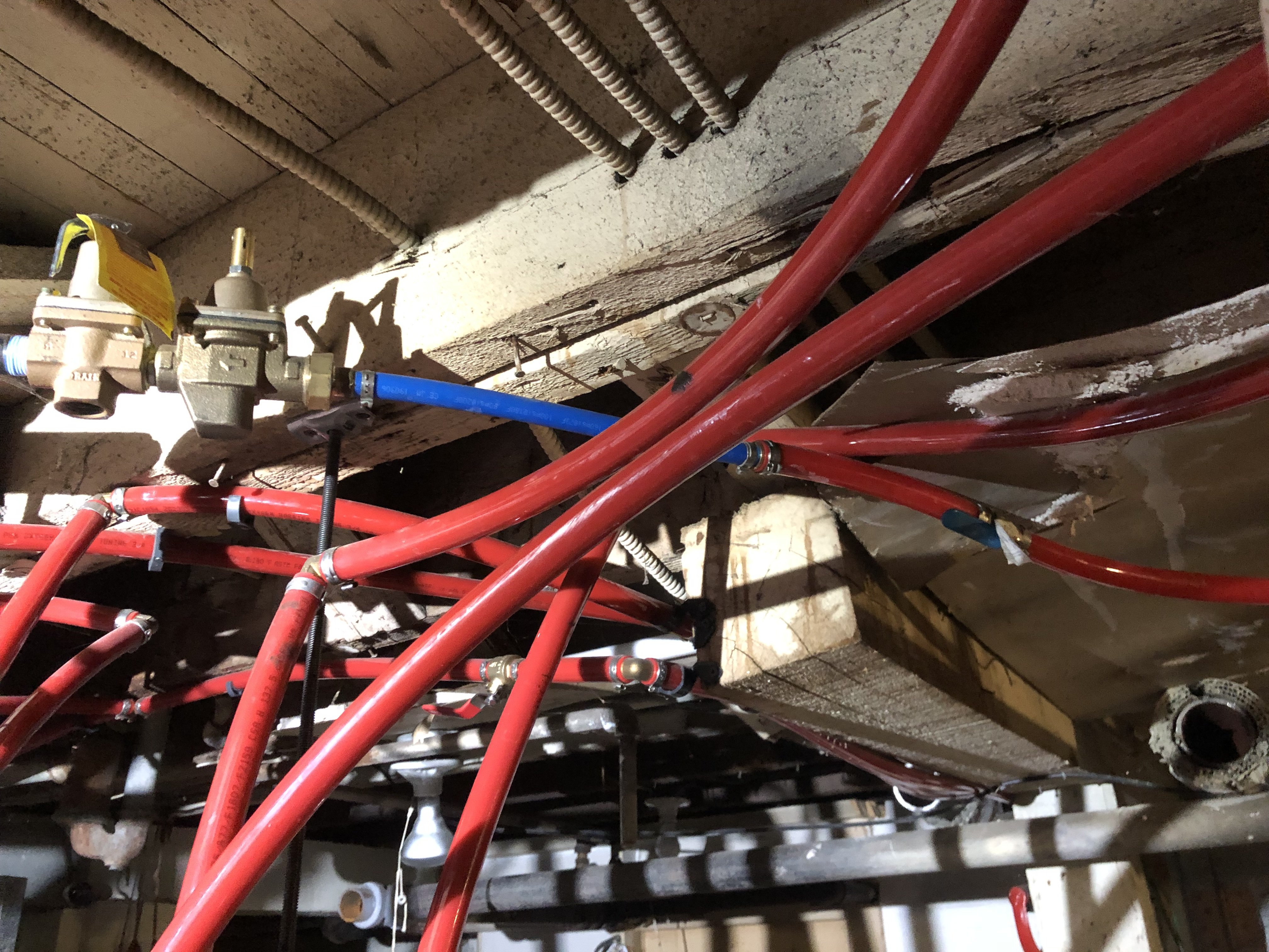
@hot_rod- yeah I was thinking of that idea…no it has always had problems and is only 3 years old. I have more pictures coming later today but here is the return stack…it leaks a lot so I plan to redo it. As you may be able to see they put a purge valve on the last return line.
 0
0 -
the circulator pump in the less than 3 years was replaced twice …set on high from what I remember but will check…
Grundfos UPS15-58FC 1/25 HP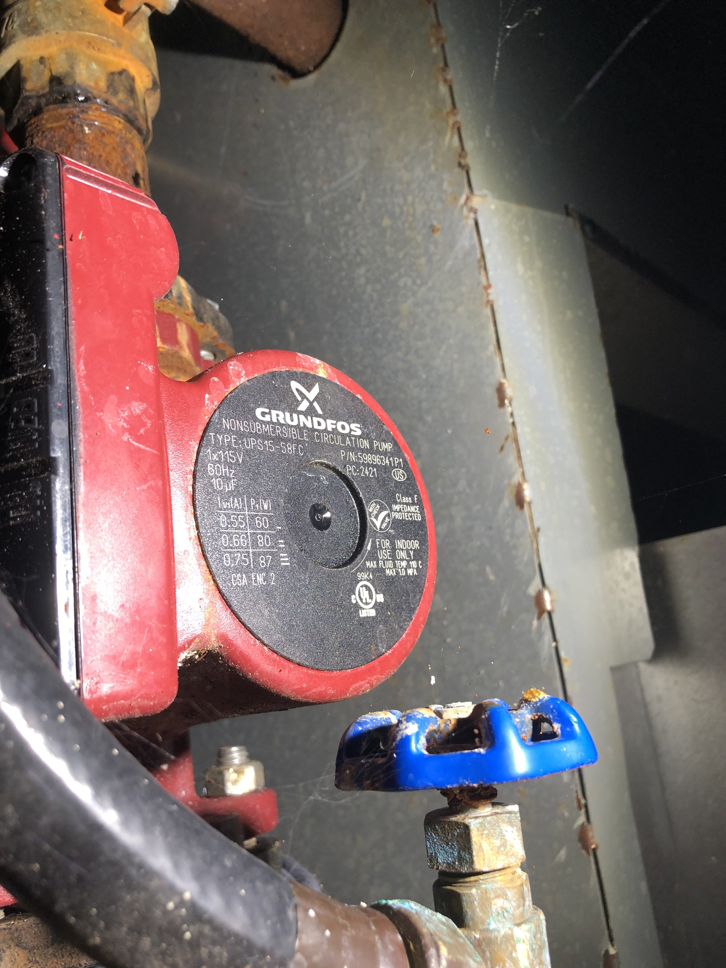 0
0 -
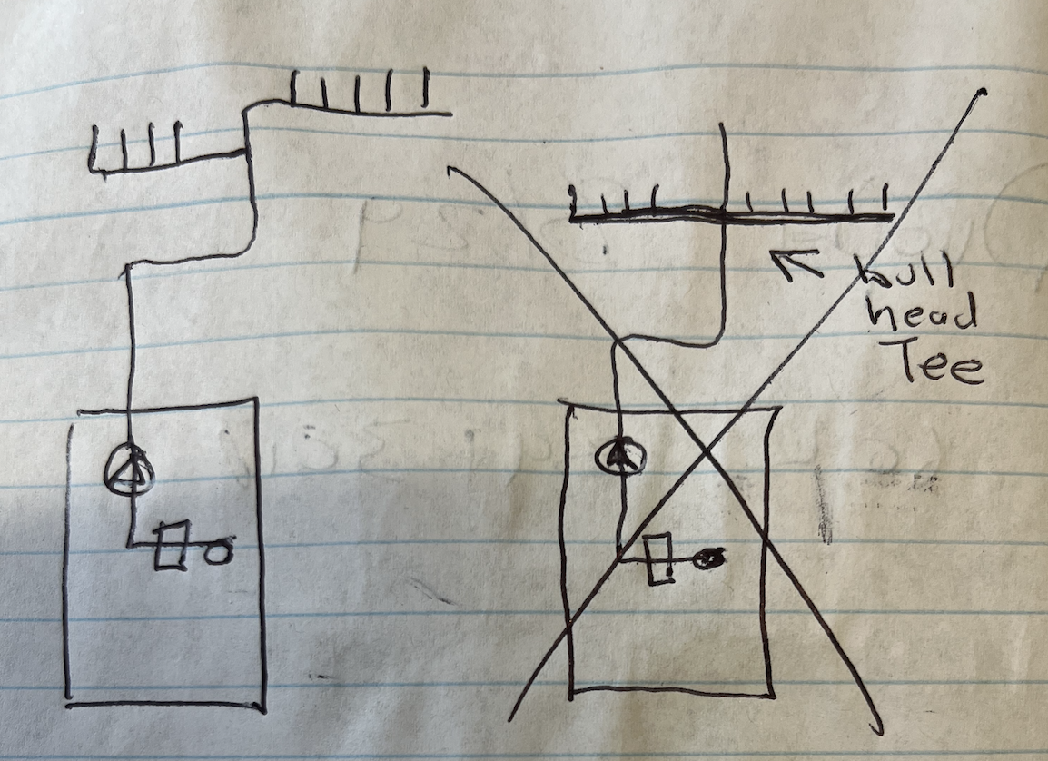
So looking at this mess of PEX it appears that there are 9 different zones (I know this is a one zone system but I'm talking each apartments as a zone). and your drawing shows that any zone may have additional tee fittings in the zone.
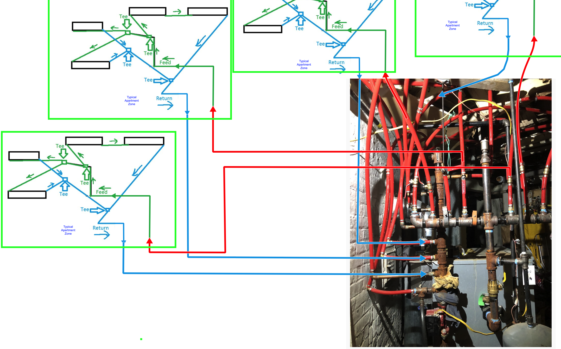
This will make for air problems and adding a valve to every return will not resolve the air problems if the above diagram I have shown represents your system.
There needs to be an air vent on each loop in order to get the air out. Or you must provide a ball valve on each tee inside the apartment zone to purge those individual loops.
If however each apartment is a series loop with no tee fittings inside the apartments then the existing supply ball valves can be used to isolate each zone in order top purge the loop.
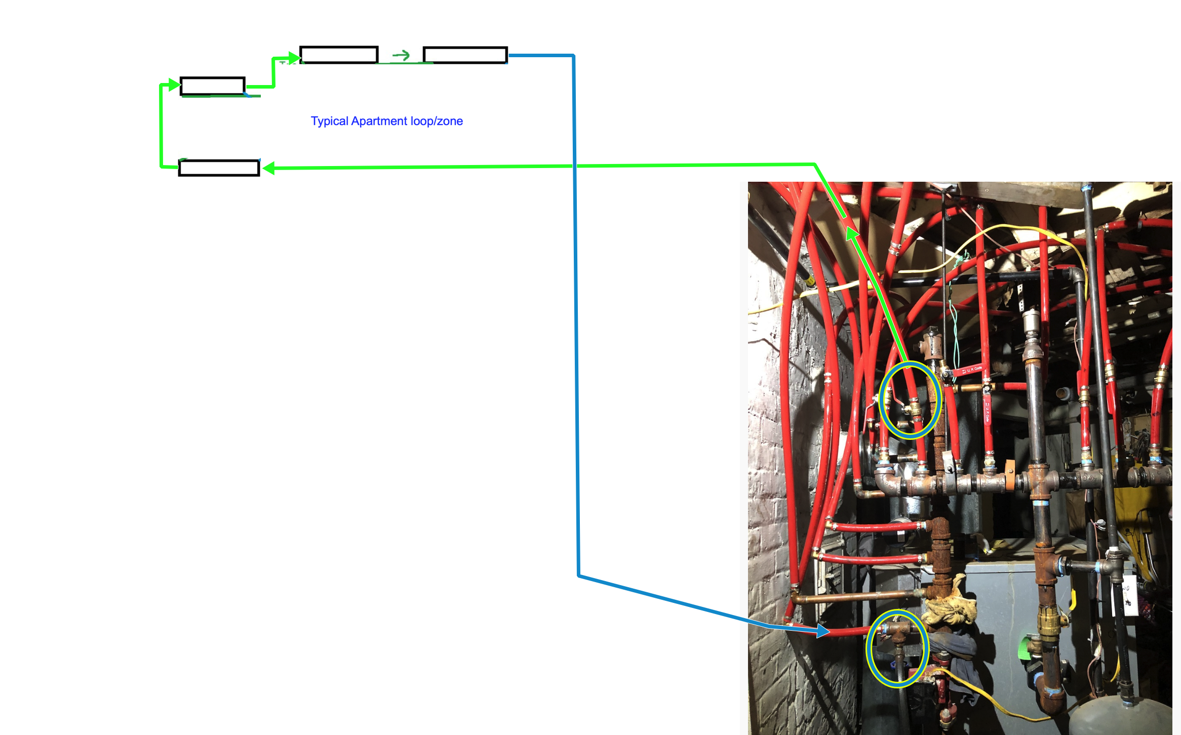
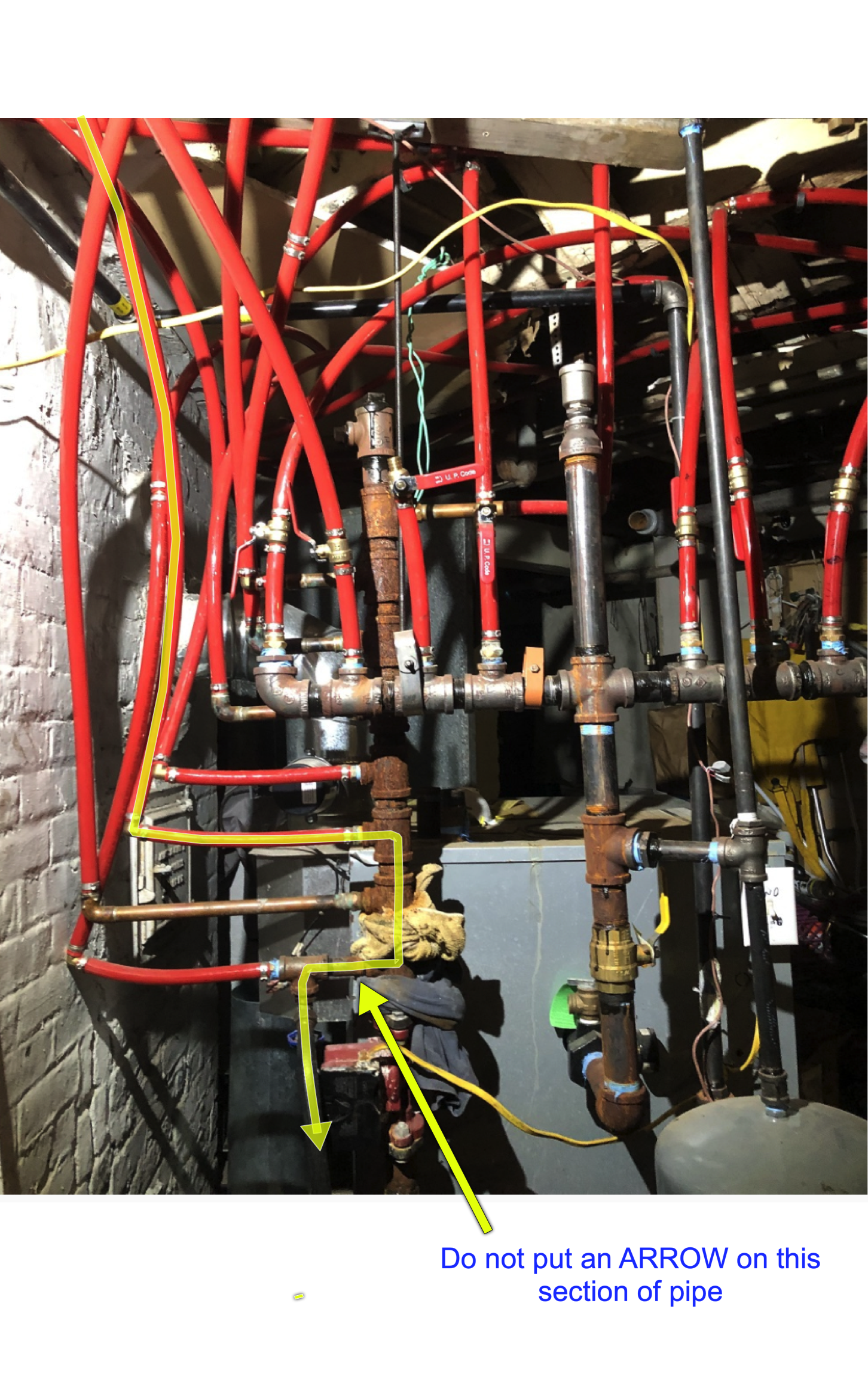
By closing all the supply valves (Green Oval) and opening only one supply ball valve, the water can only go thru the one path. (with no tee fittings) and end up at the return with all the air purging in that loop. Then it will exit the one boiler drain valve just before the circulator pump (Green Oval)
And as long as you don't put a water flow direction arrow on this one section of pipe then all the other loops can use the same boiler drain for purging.
Edward Young Retired
After you make that expensive repair and you still have the same problem, What will you check next?
0 -
Thank you for the responses and Ed for the detailed drawing and explanation.So you are correct that this system is not a complete series loop type system but instead uses multiple tees as my drawing kinda reflects. It of course is much more spread out through out the basement and apartment building.
I thought of the idea of putting a shutoff valve at each tee to help isolate but that would be extremely time consuming in this maze of pex. Some of the feeds/returns are boxed in or in drop in ceilings of each apartment.
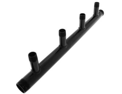
To resolve the return stack manifold leaks my idea was to use a manifold like in the picture instead of multiple 1 1/4 black pipe fittings. They all pretty much leak so since I would be redoing the return was why putting the shutoff/purge on each return line was an idea. My thought was as in your yellow arrow drawings return path, it may not completely allow all the air to escape properly traveling that path. Of course why complicate things if the one purge valve will work then I will keep it that way when redoing it.So it seems putting an air vent on each loop will be the easier method….
 0
0 -
 0
0 -
the other situation is the attic apartment has no heat so uses plug in electric. I found a way to get the lines up through the stair wells of each floor but it is a long way to run the lines and have no access easily below the attic apartment to try and make it a complete loop easy. There is a small crawl space above the attic apartment but that is not a good option. It will be tricky..
0 -
What level of finish are these apartments? Could you run them along a wall in the apartment? You can also use fin tube baseboard along the wall with the return in the enclosure but that would have to be its own zone because it wouldn't balance with cast iron or convectors or whatever the rest of the system is.
0 -
the apartments are not high end by all means, I am an electrician ,plumber and carpenter by trade but in the last two years have been working on heat systems too since most places I work end up having other issues to work on. My favorite is steam but to answer your question …all apartments are copper fin tube baseboard. The attic has all the old steam lines (two pipe) and cast iron still in place but the boiler was removed two years ago. I have removed wood baseboards to run electric many times but never to run hydronic or any type of plumbing…..
0 -
Just one more question on this pex puzzle , since no air separator is in the system would it be worth the work to put one in? Since air is a huge problem it seems so but I really can't see an easy way to add one unless perhaps a vertical one…
0 -
An old timer trick to remove air from monoflo® with convector systems where the vents were behind painted covers and not easily accessible, was to operate the circulator pump at a higher pressure and lower temperature to have the air be absorbed in solution (Boyles Law) then heat up the boiler and drop the pressure and let the air vent near the boiler. Then let the water temperature drop and increase the pressure again to absorb more air from the loops. (…rinse and repeat)
I know you don't have convectors or moniflo tees but the principal will work. The idea is that cold high pressure water absorbs air. It actually makes the air dissolve into the water. Hotter lower pressure water releases air, the air actually bubbles out of the water. This trick kept the mechanic and his dirty boots and fingerprints off of the white panted covers and light colored rugs upstairs.
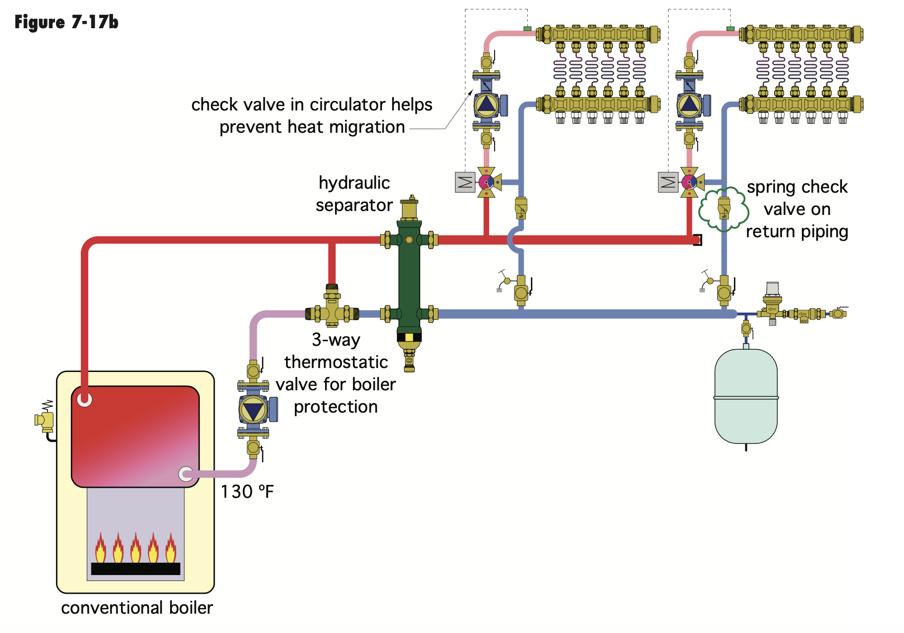
If you are repiping, and you want to make Boyles Law work to your advantage. Add the air purger right after a valve on the supply port of the boiler. Then pump away from the expansion tank that is connected to the bottom of the air separator.
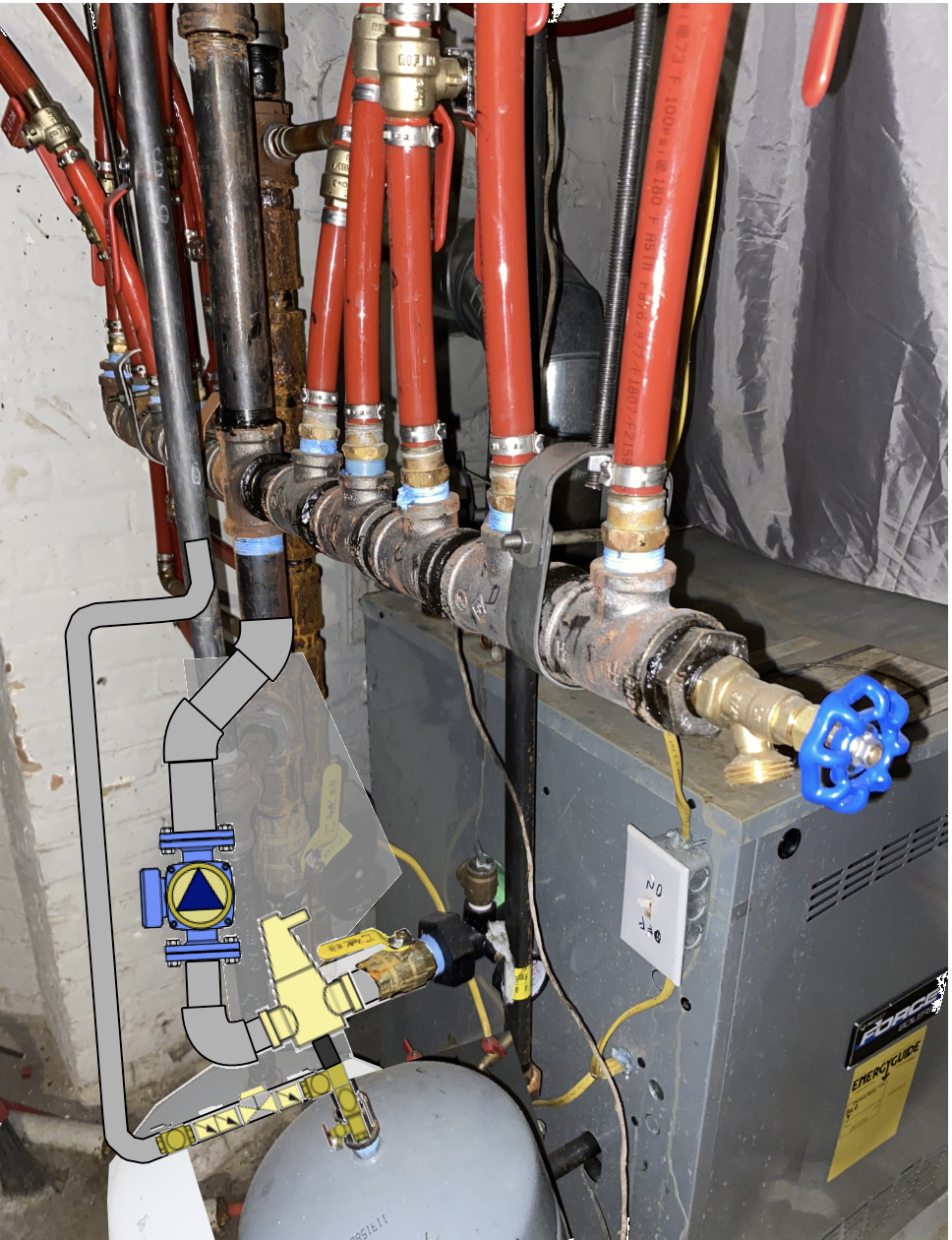
This piping arrangement actually puts the lowest pressure and the highest temperature of the entire system in the same place, along with the device that can remove the air when it gets there. You will be amazed at how the air just goes away after operating the system for a few hours. all of a sudden radiators that never were hot before will warm up and start heating the rooms.
Edward Young Retired
After you make that expensive repair and you still have the same problem, What will you check next?
 1
1 -
Ed, thanks so much for the knowledge and drawings …love learning ! I was thinking of moving the circulator over to the feed and since repiping anyways it will work out easy enough. It looks like black permatex or something on some fittings …perhaps to prevent corrosion or something..
I will update the final pictures for feedback
0 -
The Black Permatex™ may be the thread sealant that the pipe fitter used for those particular connections. I would not think that it was painted on after the fact to prevent corrosion.
The air eliminator located on the supply side of the boiler and the inlet side of the circulator pump will get you the best air removal system. I had a customer with constant air problems and expansion tank water logging issues for years before I even acquired this customer. One day the boiler sprung a leak and I quoted a new replacement boiler. When I installed the replacement boiler my top installer was going to just put in the boiler the way the old one came out with the circulator on the return and the regular expansion tank in the rafters.
I had just taken a one day seminar hosted by @DanHolohan , the creator of HeatingHelp.com, and told my installer to put the new micro bubble air separator on the supply pipe and the new diaphragm expansion tank and water feed piping connected to the bottom of the air separator. Then install the circulator pump after the air separator just as I have it in the diagram I provided you.
My installer thought I was crazy for suggesting that design but he followed my instructions.
8 hours later the job was ready to be filled with water and to the surprise of that installer, the system was much easier to purge the air from the system, and after the boiler fired up and circulated the hot water thru the system, all the other problem sections of the system that caused years of air problems were air free within 15 minutes. To this day, almost 30 years later, that system has never had an issue with air. Let the science work for you (Boyles Law) not against you.
Not every system is easy to adapt the "Pumping Away" design to. When the zone manifolds and pipes are too close to the boiler, and you don't want to repipe a complete new manifold from scratch, then you need to work within the confines of what is there.
Edward Young Retired
After you make that expensive repair and you still have the same problem, What will you check next?
0 -
Hi Ed, thanks again for the info….so I showed my Dad the new proposed re-pipe diagram and explained it in detail…he is a retired master plumber and also hydronic heating system installer for years. I worked with him when in my teens so learned plumbing and some heating. So long story short, he said never to put the circulator on the feed side but I have seen both and of course researched it for hrs. So I am buying him the book by Dan after what you sent me plus more research like below:
My question is do I need a flow control valve since the circulator has a check valve already in it?
0 -
If someone thinks the circulator goes on the return they haven't learned anything in decades.
A flow check and flow control valve are the same thing. You don't need 2 in the same pipe.
0 -
yes mattmia2… my Dad retired years ago he is 80 but I agree so that is why I am sending him the book…after I read it of course…
0 -
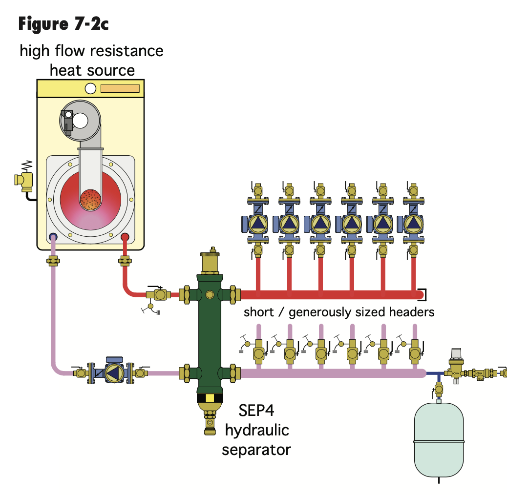
There are some exceptions. Some high pressure drop mod con boilers prefer the pump on the return to add the delta P to the hx to overcome pressure drop, eliminate potential flashing.
Also with a cast boiler the pump can be on the return IF the expansion tank is placed upstream. So you really need to see a drawing or installation to gather all the data.
It is not so much about where the pump is located on a hydronic system, BIUT where the expansion tank connection is in relationship to the pump(s). Pumping Away
Plenty examples of pumped returns in various Idronic issues.
 Bob "hot rod" Rohr
trainer for Caleffi NA
Living the hydronic dream0 -
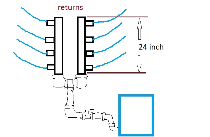
just update the manifolds arrived today , they are 24in long each and have 4 branches each 6in apart. The 9th apartment will have new copper fin baseboard next week once I finish the re-pipe of the boiler. So I posted a picture of my proposed layout of the return. It is all 1 1/4 black pipe , was planning all copper since I found a manifold with 10 branches that each branch was only about 4in apart but then would have to do the whole return in copper so went with the black pipe.
The 9th apartment I will have to add a Tee to the top of one manifold, would this setup be ok with one side having 5 return lines?
If I put both manifolds on top of each other it of course ends up over 4 ft vertical…
 0
0 -
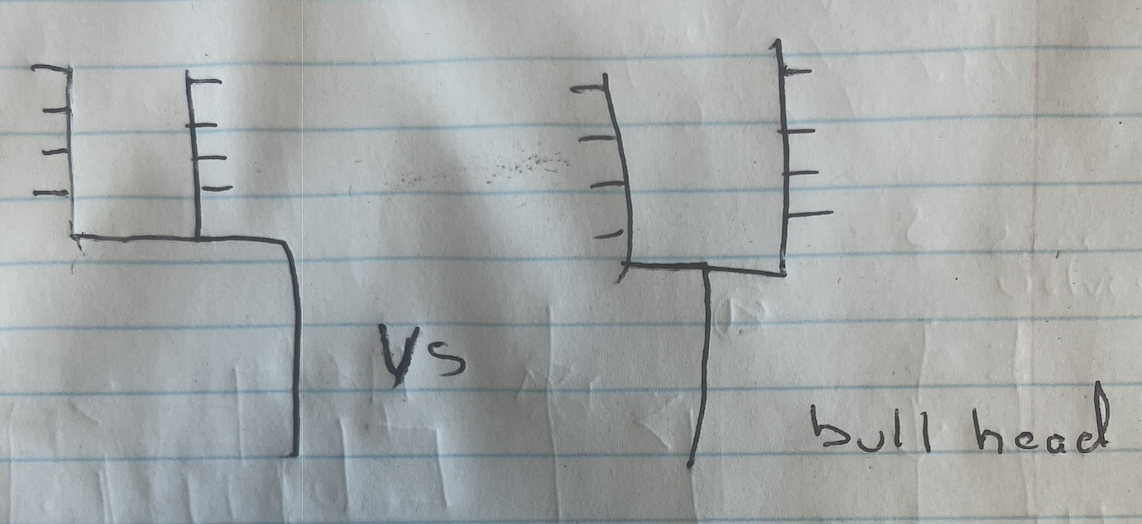
A sutle piping change suggestion to avoid a "bull head" tee connection. Flow through a bull head tee doesn't always split evenly. The use of a bull head tee arrangement was banned in code books for years, it may have been deleted.
It is not an issue in plumbing where you have plenty of pressure, but in hydronics they can cause flow misbalance. Easy enough to avoid.
 Bob "hot rod" Rohr
trainer for Caleffi NA
Living the hydronic dream0 -
yes that makes sense to me and I can see why it could possible cause an issue…it is frowned upon in plumbing too …thanks!
0 -
hot_rod, I was thinking and just so I am more clear…I thought a bull head tee was a larger branch than the two runs? Either way the flow is better in the drawing you sent and how I plan to pipe it.
I cut everything out yesterday except the feed manifold is still intact with all the feed lines. Since just the feed manifold is the only thing left is there any benefit to redoing the feed/supply manifold too?
0 -
answered my question after seeing an oldert post on bull head tee on heatinghelp :)
0 -
Do you need a Flow valve if the circ has a IFC? NO!
Dad said "Never put the circ pump on the supply" Why? because the fiber pump seals don't hold up under that higher temperature. the return side is cooler. But the wet rotor pumps don't have pump seals anymore. So use Boyle's law to your advantage.
Edward Young Retired
After you make that expensive repair and you still have the same problem, What will you check next?
0 -
just an
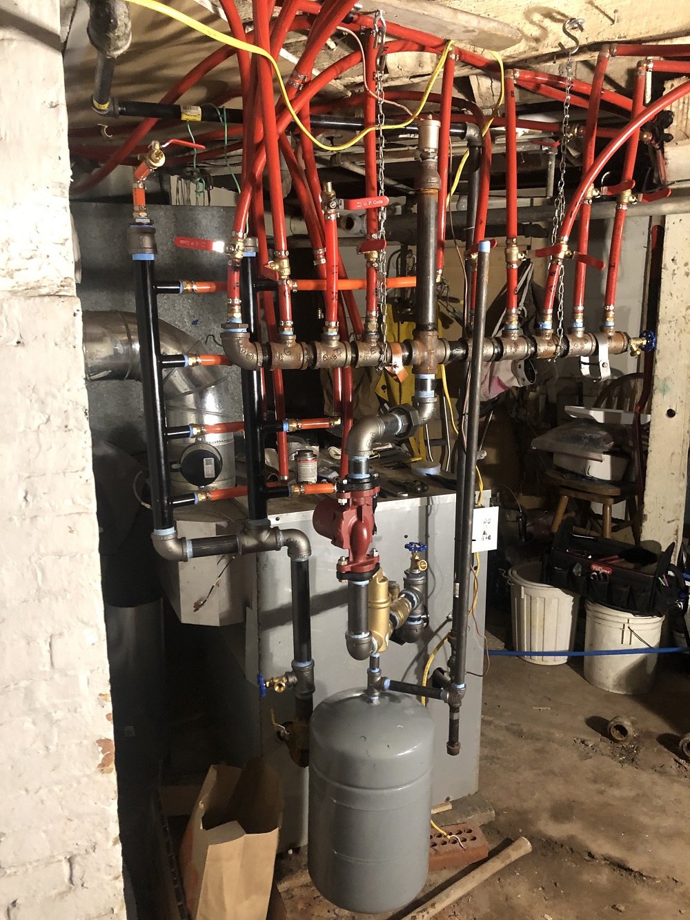
update picture, any critiques are welcomed …I had a circulator flange with shut off valve but just no room for it…I had to cut all the supply lines and raise the manifold already so adding the flange with shut off added even more height.
the circulator I originally had the motor facing out but the electrical box was on opposite side of the wire, may still need to add a long wire to make it neat but will decide on that …perhaps just switch it back to motor facing out
I would have piped it so the supply manifold was further left to the wall but then it would block the return lines even more…should have just redid the supply manifold too it would of taken up less room and look much better..
was going to use 45's instead 90's but that also added a little more height..hopefully don't loose too much pressure with the 90's
I think permatex RTV silicone it was used on the pipe threads, pipes didn't want to come apart
0 -
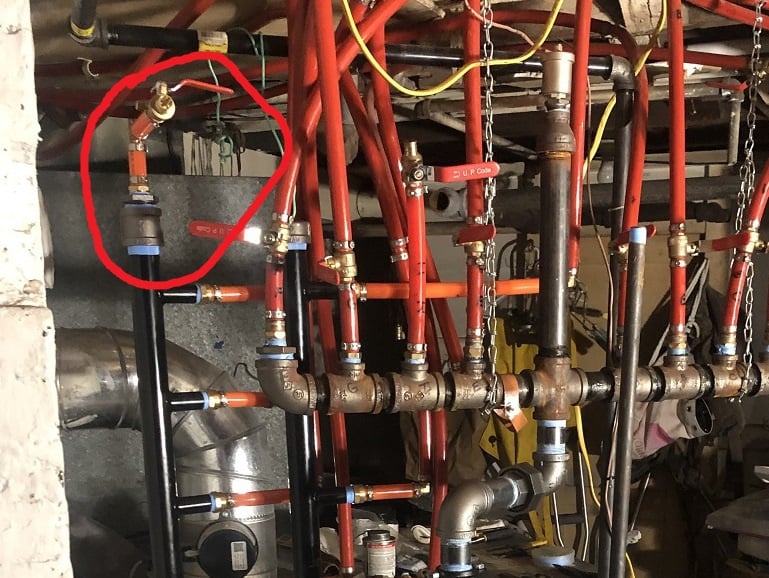
Piping work looks nice!
If anything I would have repiped the supply to get rid of the bull head tee.
Pipe the supply like you did the return, two tees splitting the flow.
With that good air purger, that high vent on the riser could have been eliminated.
A vertical air sep would have saved a few ells, no big deal on pressure drop with those ells.
Isolation valve on the expansion tank is helpful for service and checks. You do have the main ball valve and all the branch ball valves to isolate the tank, with minimal water loss.
Are the loop hangers replacing the dog leash chain? Or vice verse?
On to the wiring clean up ? :) The Romex isn't safe or legal used like that.
 Bob "hot rod" Rohr
trainer for Caleffi NA
Living the hydronic dream0 -
Bob, yes I agree getting rid of the bull head tee and piping it like I did the return or your drawing would for sure be better. The owners son ,the guy who put in the system , showed up and drilled me on my re-piping and said the air separator wasn't need because he put in the air valve on top of that Hanukkah candle looking supply plus wondered why the circulator was moved not to mention other things…. I explained the reason behind it but he wasn't hearing it…not to mention he had supply lines labeled wrong which caused me headaches…I know this isn't a question or the place to post this but I do appreciate the help on this form and thank you !
I did also put copper fin radiators in one apartment , one of the ones labeled wrong, and used a complete loop! The only one in the building lol
0 -
Looks line you are not finished piping the water feed. if you have one valved flange, it looks like you can fit one in there by using a shorter nipple on the inlet side of the pump.
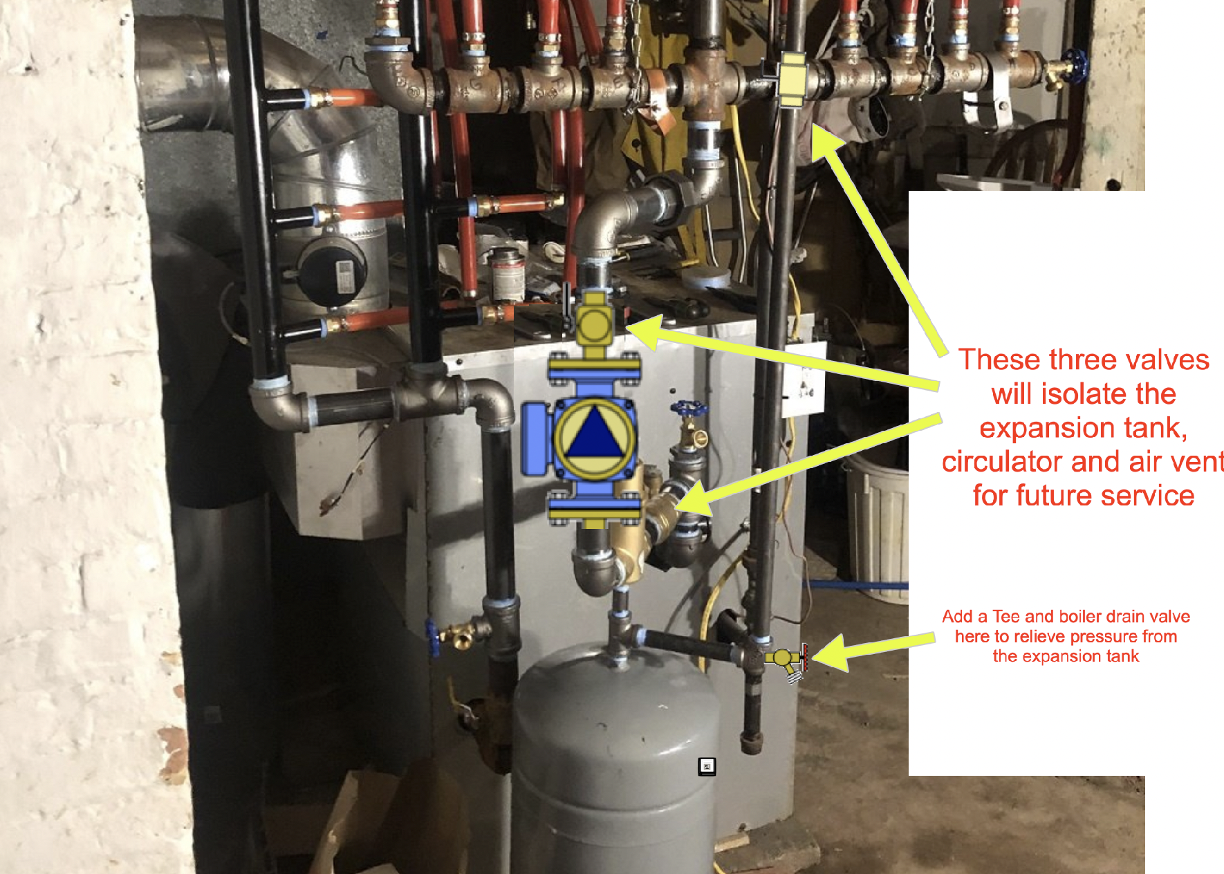
By shutting off three valves, you can isolate the major parts when service is required, without draining the entire system.
Edward Young Retired
After you make that expensive repair and you still have the same problem, What will you check next?
0 -
@valentino said:
"I explained the reason behind it but he wasn't hearing it"When I find that someone chooses to not understand this information, I find it easier to ask them to explain Boyles Law of Dissolved Gasses and how it applies to the design they decided to use. They will not be able to do so because they don't understand it. Then maybe they should look it up in the library because you can't believe everything you read on the internet.
Chances are they have not been to the Library recently and would not know how to find that law of physics, let alone how to ask a librarian for information.
Edward Young Retired
After you make that expensive repair and you still have the same problem, What will you check next?
0 -
so I wanted to update the progress on the boiler, after purging and firing up the boiler I noticed the top returns on both side not getting too hot so opened the ball valve on the left top return and let the air out. It worked right away and when I was piping it was thinking air vents on the top of each vertical return manifold may be beneficial. My concern was perhaps with air vents some new air could also be introduced in the system. The left top ball valve is for a new apartment that has no baseboard yet …So would it be advantages to add in the vents?
The system worked fine after removing the air.
I also put ball valves on each side of the return and supply tees that I had to put in the one apartment when adding three rooms of baseboard to what was already there. (the three rooms had none)
The rooms I did are a complete loop.
The owners don't want the boiler on until Oct. This gives me time to go back since I also found several apartments had some copperfin baseboard orientated the wrong way so will have to re sweat them too…
0


Categories
- All Categories
- 87.6K THE MAIN WALL
- 3.3K A-C, Heat Pumps & Refrigeration
- 59 Biomass
- 429 Carbon Monoxide Awareness
- 124 Chimneys & Flues
- 2.2K Domestic Hot Water
- 5.9K Gas Heating
- 119 Geothermal
- 168 Indoor-Air Quality
- 3.8K Oil Heating
- 78 Pipe Deterioration
- 1K Plumbing
- 6.6K Radiant Heating
- 394 Solar
- 16K Strictly Steam
- 3.5K Thermostats and Controls
- 56 Water Quality
- 51 Industry Classes
- 50 Job Opportunities
- 18 Recall Announcements