Vent placement in home 2-pipe steam heat system
Comments
-
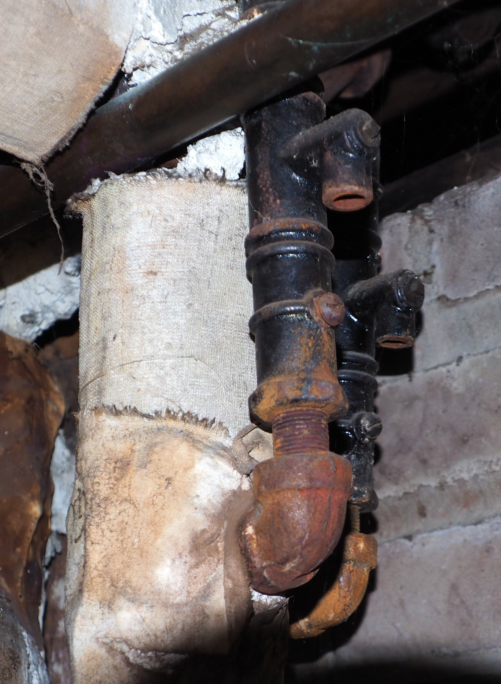
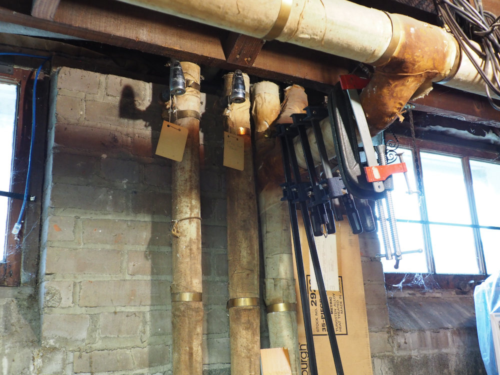
FYI, a clarification of the lingering old return vent that looked odd in design to several people. Well, there are actually two vents in the pic that appear as one. See pic. Note that there is a a screw (for adjustment, or plug?), and there is a square head screw cap at the little elbow (direction option for attaching something?).
 0
0 -
Might have been part of a setup designed to hold vacuum. What do those elbows connect to, under the old vents?
All Steamed Up, Inc.
Towson, MD, USA
Steam, Vapor & Hot-Water Heating Specialists
Oil & Gas Burner Service
Consulting0 -
@pacoit , here is a discussion of steam radiator inlet orifices and the first systems they were used on:
All Steamed Up, Inc.
Towson, MD, USA
Steam, Vapor & Hot-Water Heating Specialists
Oil & Gas Burner Service
Consulting0 -
What do you mean by "under the old vents"? To be clear, the pic is of 2 vents, each on a separate return. I do not know what the elbow on the vent connected to.
0 -
I'm wondering where the pipes go after they drop below those old vents. There are elbows that go into what looks like asbestos. Ideally they should drop from that point down into the wet return before connecting to each other or anything else.
All Steamed Up, Inc.
Towson, MD, USA
Steam, Vapor & Hot-Water Heating Specialists
Oil & Gas Burner Service
Consulting0 -
Orifice plates go in the supply union of the radiator. In combination with regulating the pressure of the boiler they limit the amount of steam admitted to the radiator to less than what it can condense so that all of the steam entering the radiator condenses to water so it can not blow through the radiator and in to the returns.
0 -
Those vents may be some variation of the KMC vacuum vent that it sounds like was just a regulator that let air out under very little pressure but would only let air in when the system was under some amount of vacuum regulated by the weight of a column of mercury. If you disturb those I would be very careful to keep them upright.
0 -
@Steamhead , Oh Ok, those and all other radiator drains individually drop down to the wet return. Heh, the pipe is straight; there is no elbow. The pic creates an illusion due to a shadow on the pipe.
0 -
I like the sound of the Imico System—-as I read out-loud to myself. Ideally, I would like to go beyond increasing venting and to some sort of vacuum system. Are there products like Dewey tri-duty air and vacuum trap or a combo steam / air (vacuum) check valve in existence?
Does anyone know if those Dewey vents were reliable?
However, in my case, I have radiators each with its own drain to the wet return, i.e., isolated. So I guess I would need some sort of piping/tubing connected to (in place of) where my basement radiator vents are tapped, and brought together at the new "combo vent".
0 -
Each radiator drops individually in to the wet return? Is there still a vent pipe connected to that?
0 -
Yes, all radiator drops are individual into the wet return which is ~6" from basement floor. The only venting are the Hoffman 1As at each drop near the basement ceiling.
Edit: to be precise, the wet returns vary in height by mains section (26", 15", 8"). They lead to a below pavement pipe to go to boiler which is in a more central part of basement.
0 -
is there a vent at each drop from each radiator?
0 -
Yes, there a vent at each drop from each radiator.
0 -
I think we've discovered a new (to us) variation of Vapor. More pics please!
All Steamed Up, Inc.
Towson, MD, USA
Steam, Vapor & Hot-Water Heating Specialists
Oil & Gas Burner Service
Consulting0 -
you have a 2 pipe air vent system but the vents i think are usually on the radiator rather than the return.
probably a modification of the original kmc that has a separate air return main to not need the special traps.
0 -
you just need vents on the mains now. you can use the radiator valve to balance the system. you don't need orifice plates, the vent and the water in the wet return will keep the steam from going someplace it shouldn't.
i'd check the vent on radiator that doesn't heat. all good vents on the radiator drops and big vents on the mains should make it heat quickly(though your system isn't super slow now)
0 -
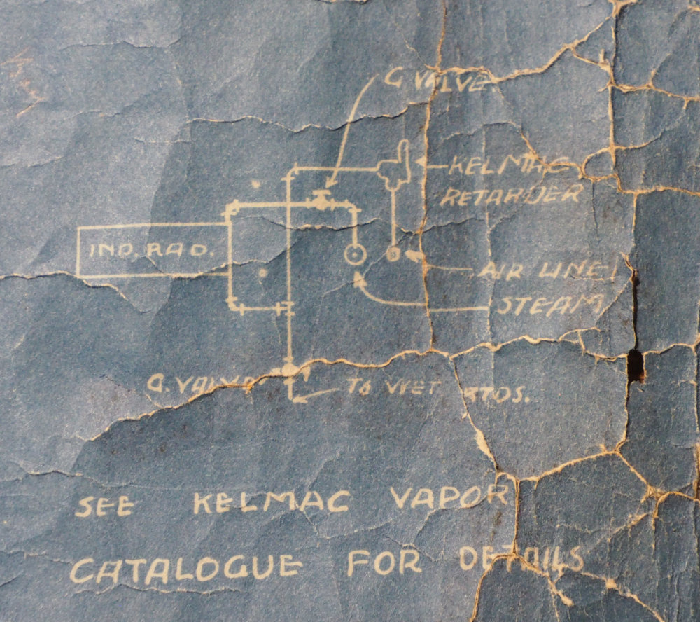
The blueprint of the Kelmac system shows a retarder tee-ed off the at radiator outlet. See pic. One might reasonably surmise that it was the original setup; then when the Bryant Gas Boiler was installed in 1924, vents were placed in the basement, i.e., the two old vents in earlier pic (maybe the Kelmac Retarders went bad); then the Hoffman 1A were swapped out in the mid 70s. Don't see any trace of mains vents' previous existence. I guess that is weird? Perhaps the traces disappeared because some insulation was replaced in 1924?
 0
0 -
Looks like the radiator in the diagram was installed in the basement- maybe an indirect rad that fed ducts going to main living areas?
All Steamed Up, Inc.
Towson, MD, USA
Steam, Vapor & Hot-Water Heating Specialists
Oil & Gas Burner Service
Consulting 1
1 -
do you still have indirect radiators?
the kmc diagram in tlaosh shows some device from the mains to the air main which presumably are the main vents.
0 -
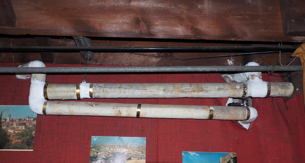
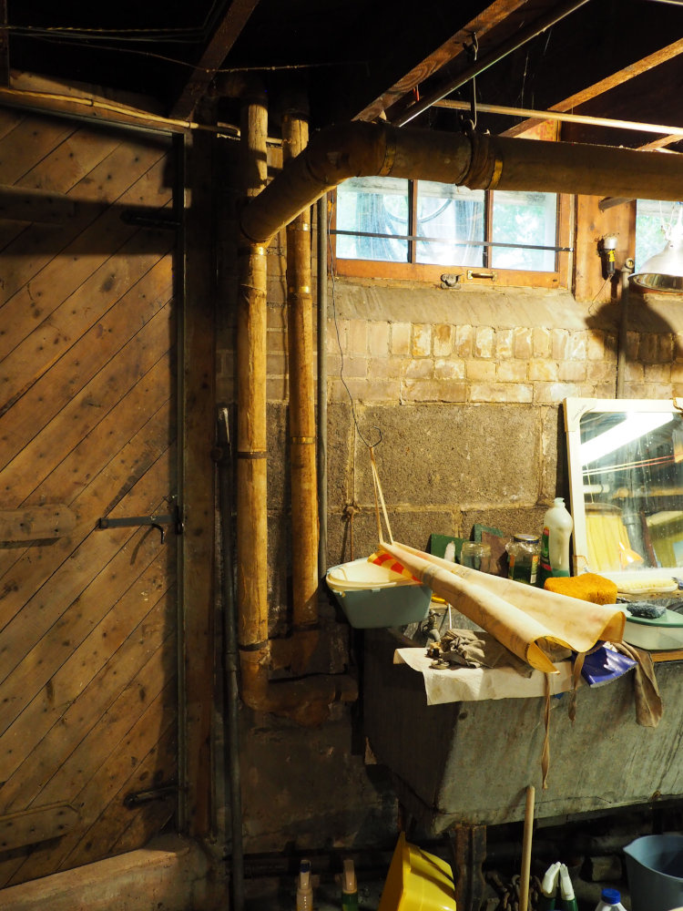
Satisfying a request for more pics. Having learned a good deal about my system, lately, It seems pretty basic. Not sure if the pics will add much insight, but here they are.
This is the "funny piping" example. Apparently a mains drip; it goes down vertically behind the curtain. Next to it, obscured, is a separate radiator drain with a barely visible Hoffman vent.
Next is the wet return about ~8" off the floor. I found 3 levels of wet returns, including 15" and 26" heights. Curious. However, there are 3 branches of wet returns. 2 wet return branches are 1 1/4" one is 3/4". Curious.
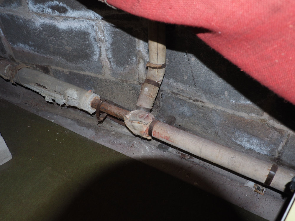
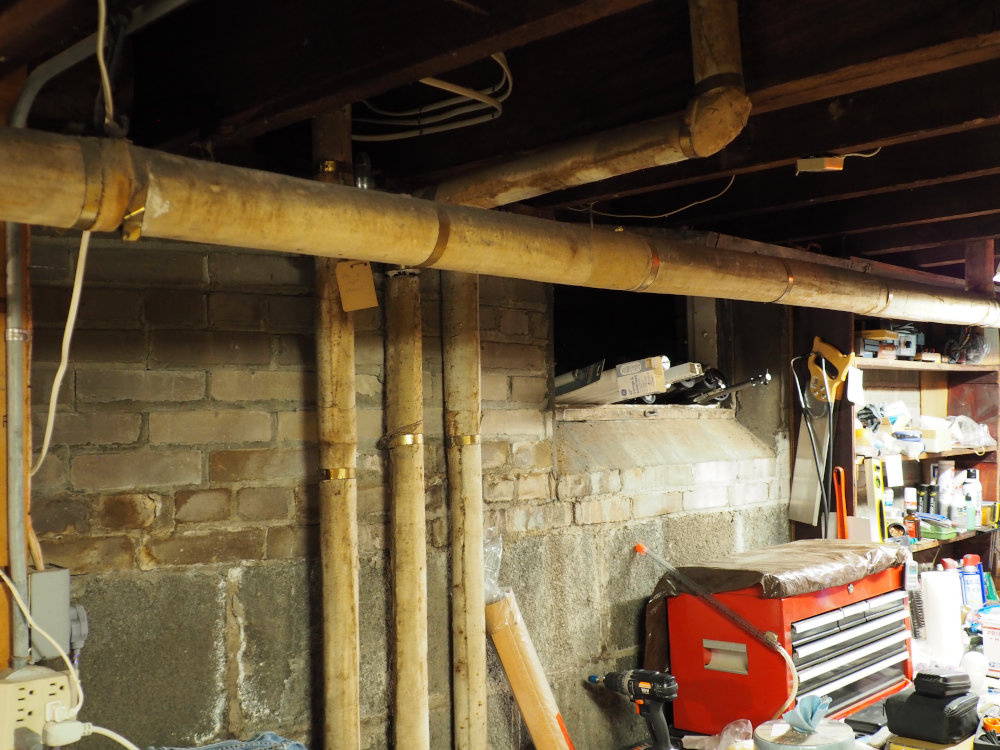
Here is the end of a main branch; it drips down and supplies up. The right pipe is a radiator drain with vent (hidden).
10 feet over are 3 radiator drains with vents.
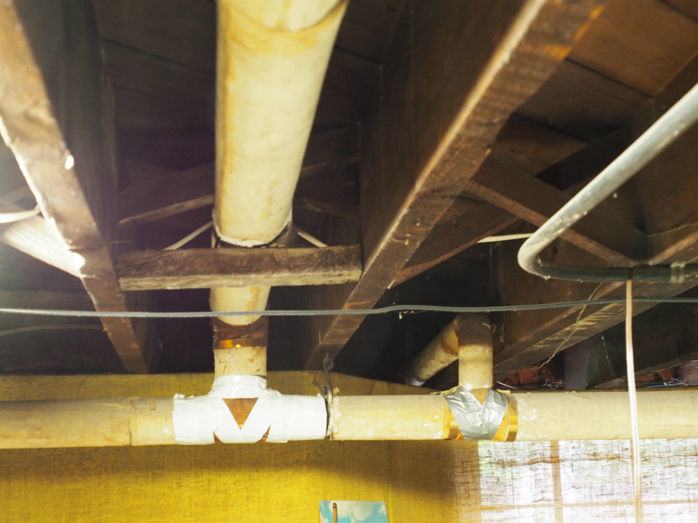
Continuing to next wall are 2 radiator drains and a mains drip and 2 supply pipes heading up.
Here is a mains crossing to the other side of the house.
I dunno. Pretty boring I guess.
0 -
it is very confusing. i have questions but i'm not sure what they are yet. there is a lot of piping there. that insulation looks more mid century than 20's.
0 -
I don't know what is happening where there is a tee and the pipe goes up and down and off the branch of the tee. Might not just be a tee in there.
0 -
Oh! I thought it was an example of radiator outlet setup for each radiator. I wondered what "IND" of IND Radiator meant. But, in fact, in the 70s. a duct (presumably with indirect radiator) that went to two floor grills "foot warmers" was removed to provide headroom to make the basement more accessible and useful!
Well, if that's the case, then the original 1917 radiator venting setup remains unknown. Could that schematic also have applied to all the radiators?
I still wonder about the schematic's reference to "air line". Was the setup originally a vacuum system?
Edit: I found piping to the removed IND radiator is still there.
0 -
the trim was probably similar. the indirect radiators would be sized to heat the room. they were to heat fancy rooms without you seeing the radiator in higher end houses. frequently they were ducted to use 100% outside air from a vent outside somewhere.
0 -
The floor grills ("registers") of the indirect radiator are one in the living room near the wall, and the other on other side of wall, the main entrance hall. Note that the living room has 2 large radiators and the entrance hall has a radiator; each room has ample heating without the indirect radiator.
Ducted outside air?
0 -
Somewhere on this site is an article that @DanHolohan wrote about how after the 1918 flu pandemic they built houses to be heated with the windows open or otherwise pull in lots of outside air because they thought that prevented illness. The duct that was around the radiator under the floor that pulled air through the radiator and out that grill in the floor or wall instead of starting with a return vent in that same room was usually connected to a duct that went outside so it would pull in and heat fresh air.
which is also probably why they converted it to standing radiators in the room in the 70's when fuel got expensive.
0 -
There might have been another version of the "retarder" that was smaller, maybe about the size of a Paul vent, which would have been installed where the Hoffman vents are now. I've seen a couple Dunham installations where they used these things as crossover traps.
Since this was described as a Kelmac vapor system, and we know that at least one version from that company used vacuum, that would have kept steam from reaching the vacuum ejector or whatever this system used to make the vacuum. It also explains the "air line" that we now know did not carry any condensate.
All Steamed Up, Inc.
Towson, MD, USA
Steam, Vapor & Hot-Water Heating Specialists
Oil & Gas Burner Service
Consulting1 -
If it was designed to have a vacuum created by some sort of vacuum pump, probably some sort of eductor rather than a mechanical pump, the mains probably aren't designed for full capacity under atmospheric pressure. fortunately you probably don't need the full capacity for a lot of reasons.
0 -
So, as is, my system, as many have suggested, seems to be woefully under vented (10-15 min heating cycle). I should clarify my use of the term 'heating cycle': it's not the boiler ON time; it is the time for the radiators to begin getting steam.
If I were to add venting to the mains, is it correct that I should place a vent at end of each main? Each of my mains branch to a Tee where the distribution takes place. So, should I place a vent at ends of each Tee section (2 vents per Tee section)?
and then the existing vents would clear the air from vertical supply pipes and radiators?
0 -
Sorry I missed this comment. Which pic are you referring to? I'll explain. Thanks.
0 -
Basically, that's it. Vents on the ends of the mains.
The major difference in your system from most vapour and regular two pipe systems is that over the years it has been modified so that the original venting arrangements have been lost, and the Hoffman 1As have been put on all the radiator outlets. In a "normal" system the radiators would vent into a dry return, which also carries condensate and in turn vents to the atmosphere. Nothing wrong with that — it should work just fine, provided that the vents work!
You mention a vacuum system. And enquire about vacuum type vents (which vent air, but hold against a vacuum). Such vents are available. Two problems: first, they are very expensive compared to normal vents. Second, you would need one for every radiator… or to add dry returns or vent lines, which introduces other problems since then they would have to be trapped or you would nave to add orifices.
Br. Jamie, osb
Building superintendent/caretaker, 7200 sq. ft. historic house museum with dependencies in New England0 -
@Jamie Hall Thank you—-and the others on this thread—-for carefully tracking the information in my comments , asking further questions of clarification, and then providing thoughtful and apropos responses. That's quite rare in most discussion forums. So, thank you all again.
Continuing with the 'add venting' option. How does one estimate the amount of mains venting needed? I presume in principle one calcs the amount of volume in the system. Does knowing system EDR help? I have 19 radiators, 2-column, 20" tall, having 5 sections per foot, for a total of ~70 linear feet. I calc 700 EDR based on instructions from this chart:
Separately, for a (speculative) vacuum system conversion, would pulling a vacuum from the returns (or mains) raise the water level of the wet return substantially? If so, what else might need to be re-engineered, or verified to be within the limits of the existing system? I'm definitely unclear on this one. Thanks.
0 -
it is the size and length of pipe you need to vent. you just need to have enough vent opening to quickly vent out that volume of air.
typically you equalize the mains and returns in a vacuum system so that the difference in pressure between the 2 is small. i'd worry about the main venting and making sure all the radiator vents work before worrying about vacuum.
0 -
With regard to vacuum. Remember that steam systems work entirely on the basis of relatively small pressure differences between the boiler, the mains, the radiators, and the returns.
There are no pumps!
Now if the system is sealed, it really doesn't care what the absolute pressures are, except that the absolute pressure controls the temperature at which the water boils in the boiler and condenses in the radiators. Higher pressure (absolute!!!), higher temperature. Lower pressure, lower temperature.
For practical reasons, we often use a shorthand reference: the atmosphere. Any pressure in the system in excess of the local atmosphere we call "pressure" — and any pressure less than the atmosphere we call "vacuum". When we are talking about pressures with the atmosphere as the reference, an engineer will use the term gauge pressure — and this is the pressure which we see on a pressure gauge on a boiler. If the engineer is concerned about the way the system operates, though, he or she will use the term absolute pressure, which is referenced to what the pressure would be in a vessel completely empty or air (or steam, refrigerant, or whatever)
All this can take a while to wrap one's head around, but it really is helpful in understanding how the system really operates.
Since we also play with liquids — condensate — we also need to take into account the change in pressure in the liquid with vertical depth. This will be the pressure at the free surface of the liquid (such as the water standing in a drip to a wet return — or the boiler) plus an amount related to the depth of the liquid and its density. In the case of water, this increase is approximately 0.43 psi per foot of depth.
Now let's look — finally! — at your question about the effect of a vacuum on the height of the water column in a drip to a wet return. And let us suppose that that wet return is directly connected to the boiler water. Remember that pressure in a liquid is related only to depth, not horizontal distance. So… if that drip is connected at the upper end to a steam main, which in turn is connected the boiler, the water in the drip will stand at exactly the height of the water in the boiler (well, there is a complication, but it's minor). Applying a vacuum to the steam main and hence the boiler makes no difference at all.
However, suppose that the boiler and steam main is operated under a "vacuum" — remember, that's a pressure less than atmospheric — but the upper end of the drip is attached to a dry return which is at atmospheric pressure. To make the pressures balanced, the water in the drip will have to fall, so that the pressure at some depth in the water is equal everywhere. Conversely, if the pressure in the pipe at the upper end of the drip is a vacuum, the water will have to rise in the drip to compensate (this, by the way, is why water rises in a straw…).
Now it is very important to distinguish between steam systems in which the entire system is sealed from the atmosphere, and which can, therefore, operate at an absolute pressure less than atmospheric — a "vacuum" — and steam systems which use a pump or eductor or some other method to evacuate air from the system on startup. They are both sometimes referred to as vacuum systems, but the principle of operation and the effect on operation is quite different, and the "vacuum" is there for different reasons.
One aspect of this affects two pipe steam systems. These, as noted, operated correctly on rather small pressure differences. Absolute pressure in the system affects the temperature at which they operate.. I have sometimes seen it suggested that the dry return on such systems, which normally never contains steam and operates at atmospheric pressure, but subjected to a vacuum — a pressure lower than atmospheric. That can be done, if the system is or can be sealed against a vacuum — but what happens to the pressure differential which drives the system? It is, effectively, increased by the vacuum — which will raise havoc with the balance of the system and the water will stand in various drips. In fact, one can get precisely the same effect by raising the gauge pressure on the steam main/boiler side!
Br. Jamie, osb
Building superintendent/caretaker, 7200 sq. ft. historic house museum with dependencies in New England0 -
@mattmia2 , Oh, right. Silly me. For the venting option it's the mains piping volume I need; the supply pipes and radiators are handled by the return vents. (I don't have risers to attach vents at top of; there is a separate supply pipe from main to each radiator. Is that unusual?)
Oh, silly me, again, regarding the (speculative) vacuum system: must equalize the mains and returns. OK.
I expect to simply add vents to my system. But, I'm interested in a vacuum system primarily as a scientific exploration. I'm intrigued by the faster heating of radiators, but even more so the prospect of modulating vapor temperature via vacuum control for possibly additional fuel savings. It's an intuition about achieving the same amount of desired heating but creating less kinetic energy in the process. For example, with boat propellers, comparing 2 propeller systems, one twice the diameter and spinning at 1/2 the rpm will generate the same total thrust as the other, but reduce the kinetic energy needed by half—-and so cut fuel by 1/2. So, for a heating system, heating water to 1/2 temperature for 2x the time will generate the same amount of heating. However, just as a large propeller needs a compatible efficient high-torque low rpm motor, such a steam system may need a resized different spec boiler. Still an idea in infancy.
0 -
the temp needs to stay hot enough that the water in the flu gases doesn't condense in the boiler. you can do what you describe with hot water systems and mod con boilers but it isn't really practical in a steam system beyond a marginal reduction in operating temp. most of the energy goes to the phase change, the energy in changing the temp a little is small.
0 -
Fundamental flaw there. A structure, such as your house, will take a certain amount of power to heat at a given outside temperature and inside temperature. It doesn't matter whether that power is delivered with hot water, vapour at some low pressure, steam at 212 if you are at sea level, hot air… it makes no difference.
Power is BTU per hour. And those BTU come in this instance from burning fuel. Therefore, you will burn a certain number of gallons of oil or cubic feet of gas per hour to heat the house.
Any system will be the same if the efficiency of the devices is the same — and most are.
A vacuum system makes no difference.
Your analogy with a boat propeller is interesting — but that is much more complicated than it appears on the surface. The ideal propellor for a given boat is one which will transmit the power required (there's power again) to achieve a given speed through the water with a minimum of loss, as propellor efficiency is closely related to slip — and the difference between the velocity of the water flow projected by the propellor and the velocity of the boat. A small propellor turning at high speed pushing a slow boat is vastly entertaining to watch — I used to see them all the time when I was a lobsterman — but is horribly inefficient. Much gasoline burned to no avail…
Same thing with aircraft — which is why all you see on passenger jets these days is high bypass turbofans. And why, in the old days, anything of any size at all had a big, slow turning propellor driven by reduction gears.
Br. Jamie, osb
Building superintendent/caretaker, 7200 sq. ft. historic house museum with dependencies in New England0 -
@Jamie Hall , I didn't see your detailed post until after my post 31.
OK, I understand the concept of absolute vacuum versus vacuum relative to atmospheric pressure. And I think I understand the rest. To test my understanding, see if the following is a fair description:
- A 2-pipe system with individual radiator drains to a wet return; thermostatic vents at drains; cold system is at atmospheric pressure; as system starts and creates steam, pressure on the supply side increases, steam pushes air out the vents until it reaches the vents, which then close; the return side retains air and remains at atmospheric pressure.
So, the steam moves through the system by virtue of its pressure being higher than the pre-existing pressure in the system; as it condenses at radiators (pressure reduces), it is replaced by more steam. When boiler shuts off and the system cools, air is drawn back into now re-opened vents, and the system returns to atmospheric pressure. - A 2-pipe vacuum system (using vacuum pump) with individual radiator drains to a wet return; radiator supply valve has orifice to limit steam flow; no vents; cold system is at below atmospheric pressure (some set vacuum); supply and return lines are under vacuum; as system starts and creates steam (at some lower temperature determined by the vacuum), not having to push air out, the steam expands quickly to the radiators; the orifices create some back pressure (some small differential between supply and return), presumably of no consequence; steam has raised the pressure in the system.
So, the steam moves through the system by virtue of its pressure being higher than the pre-existing pressure in the system; as it condenses at radiators (pressure reduces), it is replaced by more steam. When boiler shuts off and the system cools, pressure in the system returns to original vacuum (pump only tops up for vacuum leaks).
Both work on a small pressure differential, as you say. But (2) at a lower reference pressure. How am I doing?
0 - A 2-pipe system with individual radiator drains to a wet return; thermostatic vents at drains; cold system is at atmospheric pressure; as system starts and creates steam, pressure on the supply side increases, steam pushes air out the vents until it reaches the vents, which then close; the return side retains air and remains at atmospheric pressure.
-
Not bad, @pacoit ! In fact, great! The steam flow into the radiators is controlled in the second case by the pressure drop across the orifice. As long as that is controlled so that steam cannot get into the returns all is well.
Your type 2 concept actually has some real advantages, in that the temperature of boiling and condensation can be controlled by controlling the vacuum. This allows the possibility of a modulating, always on steam system — very much analogues to the modulating hot water systems — assuming, of course, that one has a modulating burner (or heat source, such as Triac controlled electric heating elements) or are willing to put up with pulse modulation of the burner.
As usual, the devil is in the details. The first problem is the vacuum pump. Ideally, once the system was drawn down one wouldn't need one — but just as in refrigeration systems operating at sub-atmospheric pressure on the suction side, vacuum leaks are difficult to eliminate. The other real hassle with the vacuum pump is controlling the differential pressure, which — to maintain system balance — has to be held within a rather small tolerance. An interesting problem in control hardware and software — not too bad if one is running at a constant power, but getting… um, interesting… if one isn't.
Then, of course, there is the problem hinted at above: preventing vacuum leaks. Ideally, as in a refrigeration system, the system could be drawn down and then charged with water vapour (that's actually your refrigerant/heat transfer fluid!) without air present. Hard enough to do with copper tube and flare fittings… and any leaks will allow air back into the system, which is not good.
Br. Jamie, osb
Building superintendent/caretaker, 7200 sq. ft. historic house museum with dependencies in New England0


Categories
- All Categories
- 87.6K THE MAIN WALL
- 3.3K A-C, Heat Pumps & Refrigeration
- 59 Biomass
- 429 Carbon Monoxide Awareness
- 124 Chimneys & Flues
- 2.2K Domestic Hot Water
- 5.9K Gas Heating
- 119 Geothermal
- 168 Indoor-Air Quality
- 3.8K Oil Heating
- 78 Pipe Deterioration
- 1K Plumbing
- 6.6K Radiant Heating
- 394 Solar
- 16K Strictly Steam
- 3.5K Thermostats and Controls
- 56 Water Quality
- 51 Industry Classes
- 50 Job Opportunities
- 18 Recall Announcements