She canna take any more, Cap'n! She's gonna blow!
Comments
-
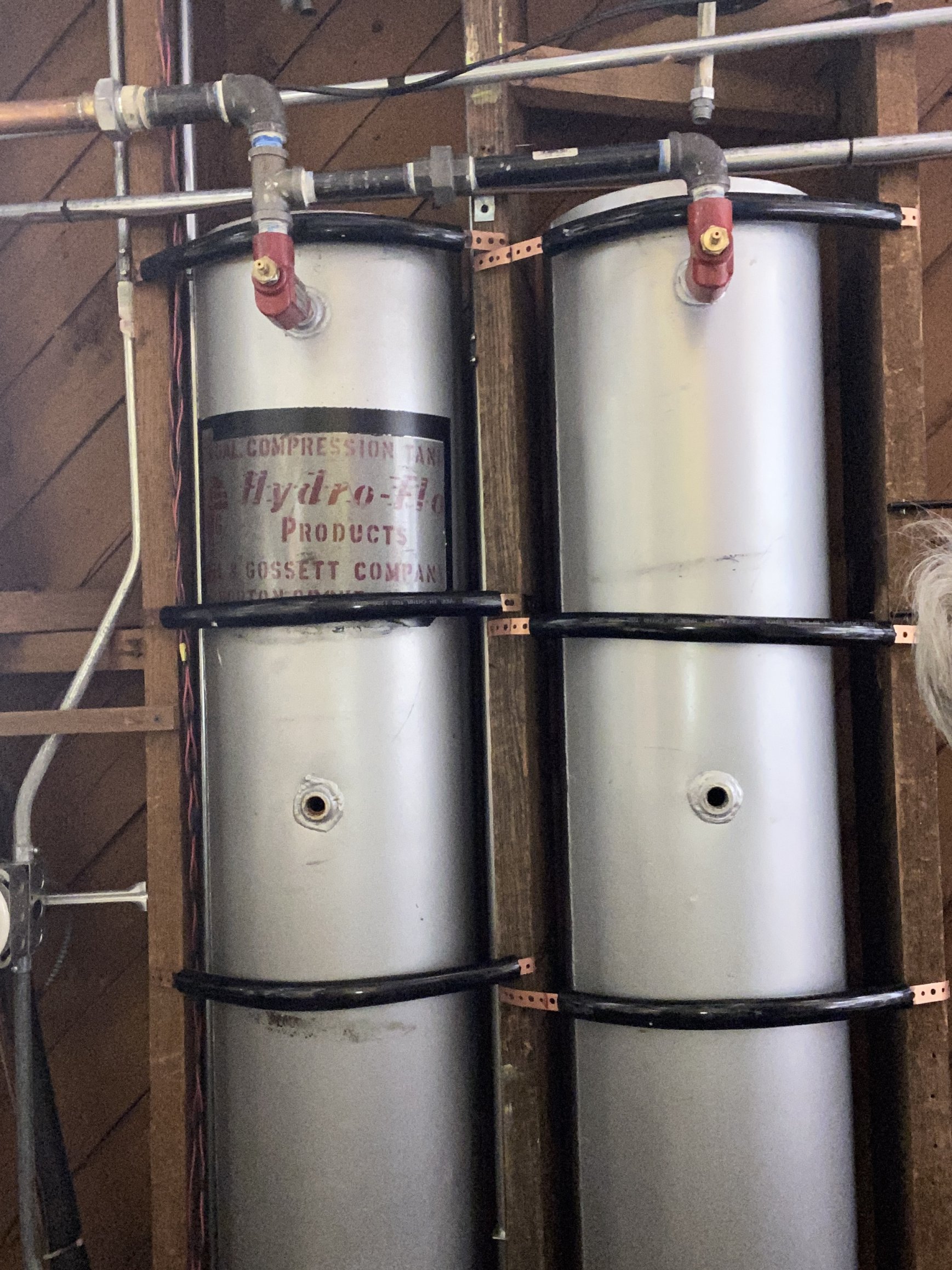
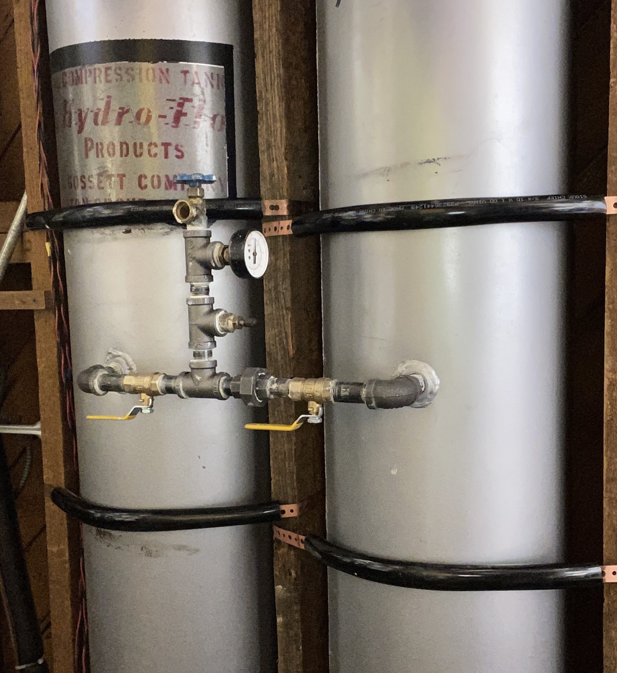
The white module mounted on bracket over tank is for bleeding any air trapped in the bracket. I supposed it could be used to relive pressure as well but would be a bit of a mess. The configuration shown in the previous post has two shutoffs to fully isolate the tanks and a valve at opposite end to allow water to be drained.
0 -
Eric, I agree with your approach. I kept my ceiling tank until I replaced the boiler. Still have the tank and the Thrush valve sitting around my shop as a space eating homage to the past. 😂


 2
2 -
Here's an update and summary of figuring out the size of compression tank I need.
First I had to estimate the # of gallons in my system, then use a tool for required tank size.Radiator Volume
Since I have a mix of radiator types, I had to use different methods. I have:- free-standing column radiators (Kewaunee) of various sizes
- baseboard radiators (Burnham: 7", Weil McLain: 9")
- Radiant radiator (Burnham)
For Burnham and Weil McLain I was able to find information from the manufacturers.
Burnham baseboard data was only for 9" model so I had to interpolate to 7".For the old Kewaunee radiators, it's a two-step process:
- Calculate the EDR
- Convert the EDR to water volume
For the EDR calculation I found a couple of sources (GreenBuildingAdvisor, ExpressRadiant) that provided the EDR based on the number of columns and the height. For the volume I used what seems to be a commonly accepted formula: 1.5 pints (0.1875 gallons) per square foot. So for example, our dining room radiator is 18" tall and has 24 sections, which worked out to:
- EDR: 108 sq ft
- Volume: 20.3 gallons
Piping Volume
This was based on visible configurations plus my recollection of how I added pipe for two additions, and split the original gravity piping into zones. I then used numbers from Table D (Page 42, Xylem Air Management
Sizing And Installation Instructions) for the volume per foot of all the different sizes.The final numbers work out to:
- Radiators: 146.8
- Piping: 56.9 (including boiler)
- Total: 203.7 gallons.
Compression Tank Sizing
I used a couple of different sizing tools. Taco has a web version of a calculator. Xylem has a downloadable program called ESP-TANKS.
These two tools provided very similar recommendations:- Taco: 44.66 gallon
- Xylem: 44.60 gallon
For these I used
- Initial Temperature: 65
- Max Temp: 170
- Initial Fill Pressure: 18
- Max Pressure In Tank: 28
- System Volume: 204
So bottom line, adding a second 24-gallon compression seems to be just the ticket. I'm prepping it now and will install it in the off-season.
Thanks for all the comments and feedback. This was quite a lively topic.
—Eric
 2
2 -
Dammit Jim, I'm a plumber, NOT a Doctor…… Eric, you are way OVER thinking this. It's your brain and you can use it how ever you want, but your time is better spent on real problems and solutions.
Isolate the tank. Put a hose on the drain cock and open it. Once pressure drops to zero, which will happen in short order, on the bottom of the red Airtrol fitting is a brass fitting, It's an air vent. Grab a straight screw driver. Open it, and it will let air into the tank and will allow the water logged tank to drain. Don't just let a little water out. Drain it COMPLETELY. This will take maybe 10 minutes… Once completely drained, close the drain cock, un-isolate the tank and allow the auto make up valve to stabilize pressure at around 12 PSI. You're done. The tank WILL be half full of water and half full of compressible air (cushion). Clean up the mess and go back to living life without having to worry about your system.
BTW, the ONLY thing I've added to what everyone else has already said numerous times, is to use the Airtrol vent to expedite draining the tank. You could stand there for hours waiting for the tank to "glug" itself to empty, but your time is better spent doing other things… Like watching old Star Trek shows :-)
Enjoy.
ME


 7
7 -
 0
0 -
Love your shop! Makes me feel better because I thought I had too many different brand battery chargers.
8.33 lbs./gal. x 60 min./hr. x 20°ΔT = 10,000 BTU's/hour
Two btu per sq ft for degree difference for a slab1 -
Haha - yeah I used to watch those reruns back in high school!
My Airtrol does not have any slot for a screwdriver, just a fitting for a wrench to open / close the Airtrol for setting the water level.
Honestly I've spent most of my time figuring out the root cause of the high PSI, then finding all the needed information to determine the size of the compression tank I need (calculating EDR, piping, water volume, sizing tools, etc). I then tried to summarize all this in my last post so that others in a similar situation could find everything in one place. I've not spent a lot of time thinking about how to pressurize my tank.
That said, honestly I think my method is actually very simple and takes less time: isolate the tank, set the water level, pressurize, piece of cake. Or as K-9 said in Dr. Who, "radial segment of baked confection". Bob's you uncle.
—Eric
0 -
you had me agreeing until star trek.
 2
2 -
I could have told him "LOST". I just finished binge watching that, and I didn't remember most of it. Guess I was Lost the first time I watched it over 20 years ago :-)
0 -
One thing I forgot to mention is that if you keep the tank, you can NOT have any means of air elimination on your system, because it WILL get rid of the cushion in the tank. I don't remember if anyone else mentioned that, and if they did, ignore me. Whereas if you switch to a diaphragmatic type of tank, you MUST have an automatic air eliminator. We haven't even talked about proper, ideal system configuration as it pertains to your pumps location in relation to the expansion tank. That in and of itself will create "air problems" in your radiators. Look up "Pumping Away" for more information.
1 -
Funny. I’m just finishing watching Lost. Maybe it makes more sense the second time?
—Eric
1 -
I assure you there are no other air eliminators in the system. Also all the components are connected per “pumping away” - boiler supply, air separator connected to water feed & compression tank, circulator. Pretty much by the book.
—Eric
 2
2 -
whaaaat? Isn’t 5 or more battery types “normal” these days? 🙄🥸😂
0 -
Hello Eric,
I am coming in to your discussion late but I wanted to make sure that you plumb in the new steel compression tank correctly for your heating system.
If you have ordered a steel compression tank with end tapping's for a gauge glass all the better as you can be assured of the water in both tanks as the water levels will be equal when you fill them again.
The piping for the first and second steel compression tank should be parallel to allow the proper orientation of the airtrol valves.
Page 4 of the Bell & Gossett AIRTROL installation sheet illustrates how parallel steel compression tanks need to installed correctly with larger header pipes.
The drawings on page four shows how the plumbing should be oriented with the new piping.
According to the information on page 4 Bell &Gossett wants the trunk line feeding both steel compression tanks to be one size larger than the tapping in the Airtrol tank fitting so that means a one inch truck line is needed. I am not sure whether a 3/4" nipple to 3/4" to 1" bell reducer would be advisable to create the 1" riser that would meet a 1" elbow to create the header pipe to be used to connect to the two steel compression tanks in tandem.
The one inch trunk line/horizontal header must be pitched up to both steel compression tanks. in your case with 2 tanks the tee and elbow must be pitched up to the ATF-12 Airtrol valves in both tanks.
The instructions do not state what reducing fitting should be used to do this coming off the tee and elbow of the one inch header pipe, perhaps a 1" short nipple and a 1" inch to 3/4" reducing bell coming from the elbow and the tee in the header pipe would be the more ideal way to let the air bubbles migrate more swiftly to both steel compression tanks. The drawing on page 4 illustrates a 3/4" short pipe nipple coming from both the elbow and the two tees which are connected to unions that are connected to the airtrol valves but there is no mention of the ideal type of 1" to 3/4" reducer whether a bushing or bell fitting and pipe nipple is preferably used to connect to the short nipples to the unions and the next short nipple that meets the Airtrol valve.
I do not know how to upload the page illustrating the diagrams showing how the piping is done for multiple steel compression tanks.
I hope I have not made any mistakes in describing this to you and I would certainly appreciate any corrections made by the members.
0 -
@leonz - thanks for your concern. I am following the instructions per the B&G document you reference.
The pipe from the boiler to the compression tank is already 1" and pitched 3/4" in 2 feet, then reduced to 3/4" to connect to the Airtrol fitting - so I believe I meet the requirements mentioned in that document.
—Eric
 0
0 -
Twinsies - ready for final piping and testing.
 0
0 -
YAAYYYYY,
May I address you as Eric?,
I am impressed with your using tubing to cover the copper coated pipe strap to prevent galvanic corrosion.
Will you be plugging the existing tapping's or creating a common boiler drain line for the tanks by installing elbows and pipe nipples to a single tee where a boiler drain is installed?
Leon
0 -
Hey Leon,
Sure call me Eric.
The tubing also made it easier to position the tanks, and avoid scratching the paint on the tanks.
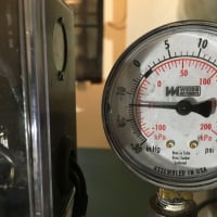
To answer your question, yes there is a common drain, as well as a gauge and a Schrader fitting for charging the system if needed. That stuff was all installed this morning.—Eric
 0
0 -
Hello Eric,
Once you isolate the tanks-shut the valves off top the tanks from the system before you fill them you can open the drains on the airtrols and open the fill valve you should not have to push air in the system at all. After you fill the tanks and have only water falling from the drains you can shut the drains and then open the valve to the system and fire the boiler to get rid of any microbubbles.
I always start the season with 180 degree high limit for a day or so and then back it down to 160 to assure the system is balanced and the sight glass is half full to start the heating season with my stoker.
I only bring it back up to the 180 high limit when the weather gets really cold on my mountain.
Please do not forget that your altitude above sea level is also a factor-with me my place is 1,140 feet above mean sea level and in my case I had a huge vacuum condition and until I isolated everything and found that the packing gland nuts were loose I tightened them 1/4 of a turn and the vacuum condition disappeared and the water level in the steel compression tank was back to normal.
0

Categories
- All Categories
- 87.6K THE MAIN WALL
- 3.3K A-C, Heat Pumps & Refrigeration
- 59 Biomass
- 429 Carbon Monoxide Awareness
- 124 Chimneys & Flues
- 2.2K Domestic Hot Water
- 5.9K Gas Heating
- 119 Geothermal
- 168 Indoor-Air Quality
- 3.8K Oil Heating
- 78 Pipe Deterioration
- 1K Plumbing
- 6.6K Radiant Heating
- 394 Solar
- 15.9K Strictly Steam
- 3.5K Thermostats and Controls
- 56 Water Quality
- 50 Industry Classes
- 50 Job Opportunities
- 18 Recall Announcements