I guess there’s a reason why plumbers can charge so much...
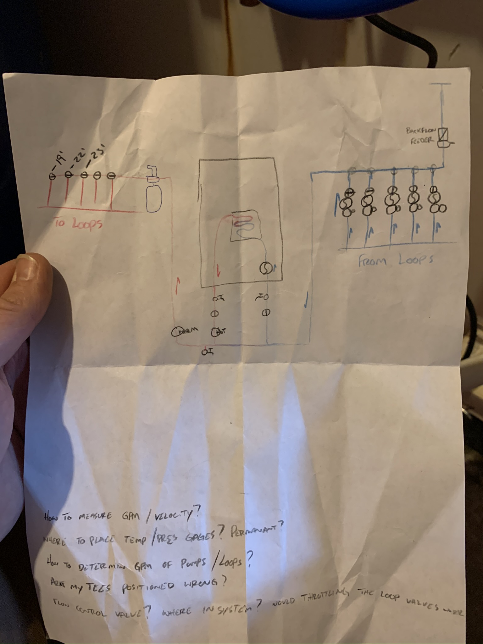
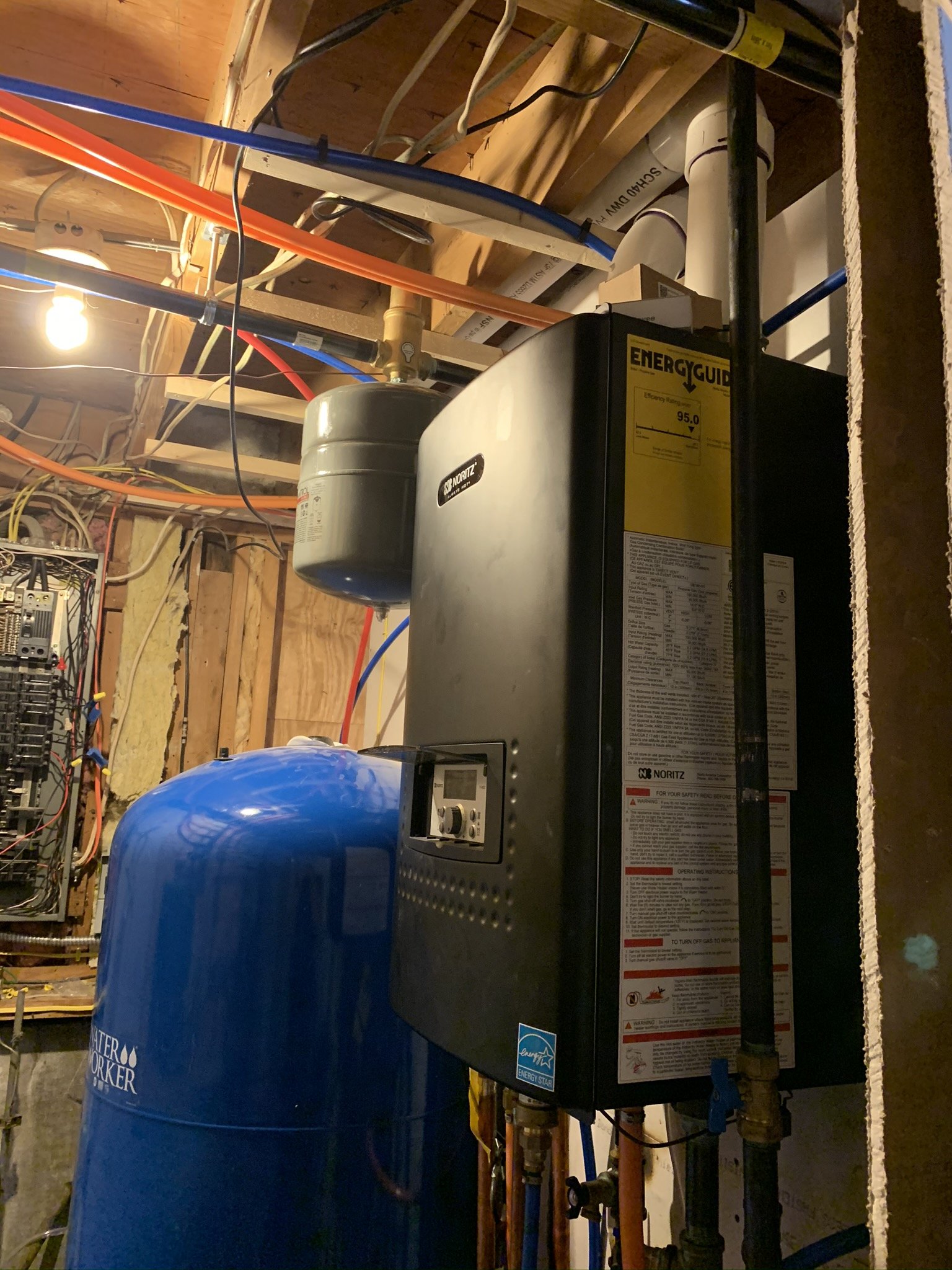
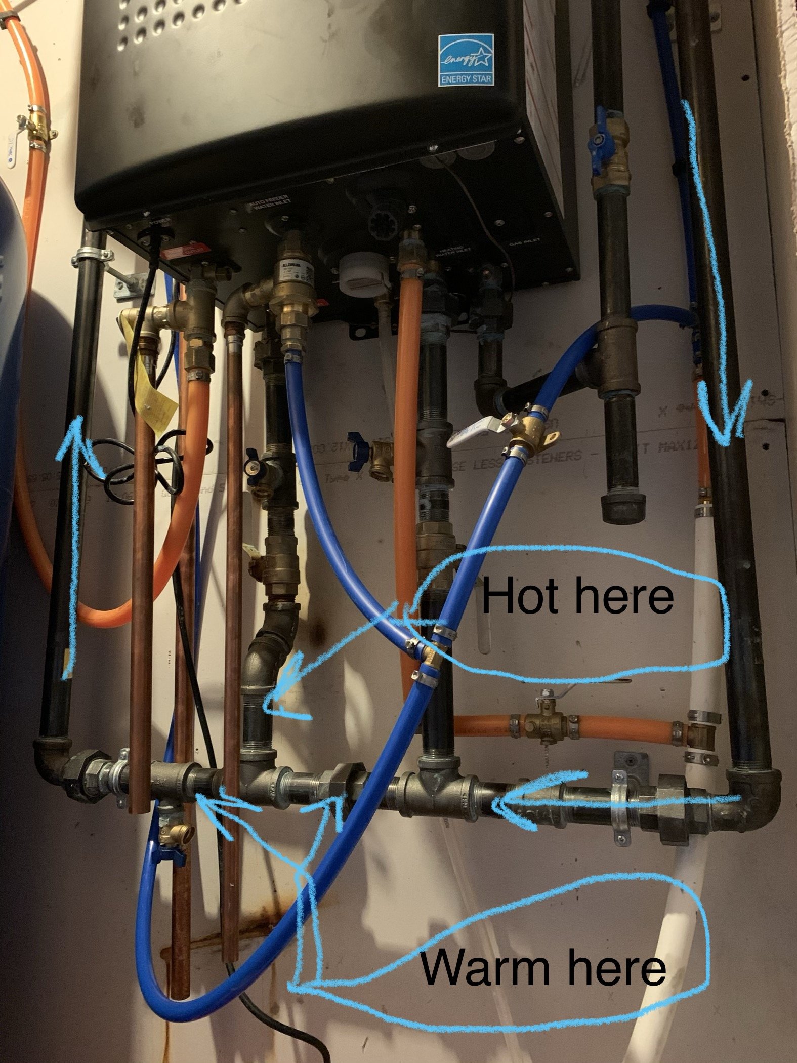
I need help. Here’s the back story... bought a house back in July that needed some “easy” renovations... fast forward to now and I still have no heat. The place had all electric base board so I ripped it all out and replaced it with hydronic baseboards (put the same size radiators back in the same spots). Bought a new Noritz 180,000btu Combi boiler. Tried soldering copper for my primary/secondary loops and learned the hard way that I can’t do that very well. So I ripped that all out and replaced it with black iron pipe and then used 3/4” PEX for my individual loops. I’ve finally chased all the leaks down, I’ve got all the air out that’s going to come out, but I can’t get it to heat my house. Let me be clear, the unit is definitely working. It makes hot water at all the taps and the supply for the primary loop is too hot to touch. Here’s the problem. Where the primary and secondary loops mix through the “common” pipe, it’s cooling the water down from the boiler so much that it’s warm at best and definitely no where near hot enough to heat a room.
Things I’ve learned through this experience:
1) this unit does not allow the primary to free flow through itself, put more simply, there is some kind of automatic controlled valve that prevents the primary loop water from being circulated constantly. It seems to circulate whenever it feels like it and I haven’t been able to figure out what triggers that. Either that or it flows at a much lower gpm than my secondary, and here’s how I know that...
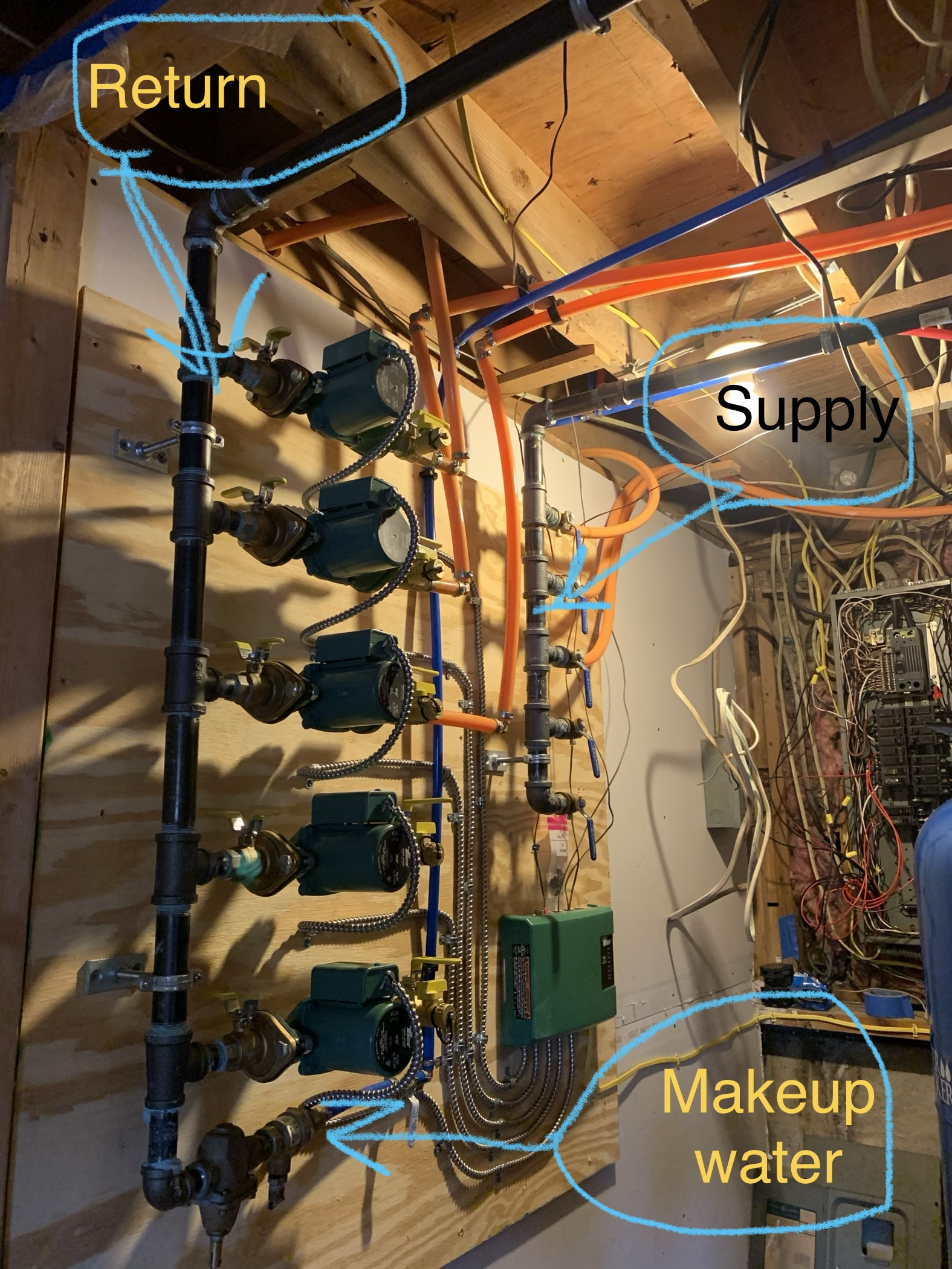
2) I have 5 loops on this system (only 3 hooked up so far, still renovating...) when only one loop is calling for heat it seems to be able to heat that loop. Not adequately, but heat is being put into the room. As soon as a second or third loop calls the pressure differential in the common pipe becomes so great that it seems to just recirculate the water from the loops and not draw any of the boiler water. I know this because of the temp of the pipes. I can’t touch directly above the tee because it’s so hot, yet the tee and everything downstream is cool due to the different temp water mixing, or just bypassing all together, I’m not sure.
3) placing a gate valve in the common pipe did not fix the issue. This is how I learned that the unit does not allow free flow of water because with the common blocked I had ZERO flow through the system with the valve shut.
I’m left to believe that there is a serious balancing problem, my design traps air somewhere, my design is severely flawed, maybe some or all of the above, and possibly other issues that I have no idea about. Please help me figure this out. Thank you for anyone willing to donate some time... I’ve attached some pictures for refeeence, please ignore my **** show of an electrical panel, again, renovating.
Comments
-
Following0
-
Does the control show you supply and return temperature when it is firing? Most do.
Could it be the control is limiting the firing rate? The manual leaves a bit to be desired. Is the ODR connected and adjusted?
How much system pressure, it needs at least 8 psi or it will not light off.
The pump inside, does it have a speed selector switch? Did you burp the air out at the internal pump.
Is that 3/4 or 1" piping from the boiler to the loop?
Bob "hot rod" Rohr
trainer for Caleffi NA
Living the hydronic dream0 -
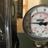
No Sup/ret temp readings (purchased cheap gages from Lowe’s but they don’t seem to be very accurate) using a lazer thermometer instead.
What’s an ODR?
System press is 15-20
Speed selector on internal pump has three settings. I’ve run it on all three. Doesn’t seem to make a difference. (Currently on fastest/factory setting)
All black pipe is 1”, pex is 3/4”0 -
Right out of the boiler is between 150-170 degrees as read from a lazer thermometer on the pipe. Everything else never gets above 1000
-
How long are your loops? Everything purged?
Looks like all the distribution circulators are on the return? Typically the circs are on the supply? If so I've never tried piping it that way?
What type of manifolds? if they are basic copper without any actuators you could flip all the circ, or a couple and see if that changes anything.
I know piped as shown below they work") Bob "hot rod" Rohr
Bob "hot rod" Rohr
trainer for Caleffi NA
Living the hydronic dream0 -
it isn't a primary loop if you're pulling out of it from opposite ends, you need to use closely spaced tees to isolate the action if the pumps in each loop. look at the manual.
do you have check valves in the pumps or otherwise have a flow check in each zone to keep it from just circulating between zones or circulating in zones that are off?0 -
are there manual valves in the zones, can you close the valves on zones that don't have the pump running and see if that helps?
btw, is this a rebranded htp or are they just buying some of the same parts?
if that control works the same as the control on an htp uft if you hold the upper left button for about 10 seconds you can use the knob to show all sorts of operating parameters like supply and return temp0 -
Btw, did you do the proper calculations for the gas line? 180 ft^3/hr is a lot of gas, you need to make sure the system is sized to supply that and any other appliances.0
-
I think if there is a dhw demand it will shut down circulation to the dh loop and switch to the dhw heat exchanger.
Do you have a purge station so you can purge your zones?0 -
Zones are purged.
You’re correct about the DHW taking priority. No issues there, the DHW is nice and hot and comes quickly.
The gas line is the one thing that I actually paid a professional to do. So I’m assuming it’s correct. Like I said, the thing makes blistering hot water. There are no other LP gas loads.
You are correct about the upper left button on the control panel, however, the displays are not very easy to understand and the literature in the manual seems that it explains somethings that my unit doesn’t have and doesn’t explain some things that it does. I’ll take the hit on that one in that I’ve not attempted to figure this one out yet by calling customer support or anything like that. Unfortunately there is extremely limited info online about this thing, I wish I would have researched that heavier prior to purchasing.
There are manual valves on each loop with purges and there are internal check valves on the circulators.
I’m not sure if you looked at my pictures but I have closely spaced tees. If my piping layout is wrong though, please explain what needs to change.0 -
The boiler installation and operation manual should give minimum pipe sizes to the common pipe on the p/s which I believe 1 1/4inch for the common piping may be your issue . With 5 zones off a 1 inch feed and each being a 3/4 zone you are exceed 4 FPS which makes it hard for air to be remove and is way to high a velocity for residential setting ,In reality you should have used one pump on the supply and zone valves on the return with your spriovent on the suction side on your pump and a pressure differential valve or a ecm variable speed pump . I’m quite sure that Noritz sells a pre fabed primary secondary set up that attaches right to there supply and return and I believe it’s 11/4 .with your zone manifold remotely mounted are you sure that it’s not air locked . For sure any plumber or hvac tech would be doing some repiping to straighten it out ,did you perform a heat lose on the home and ensure that the correct baseboard was installed and the boiler is not oversized and how many ft of baseboard is on each zone ,you may have micro zoned the zones below the minimum modulation capabilities of the boiler and now it just bounces off it limits . Not to be a tool but plumbers and heating tech charge so much because they do this day in and day out of course we make it look easy we do it all the time and it costs to be in business vehicles tools insurance it s not for free just like every white collar worker the difference is we drive the office to you ,again not to be a tool we can only help you so much and in a lot of cases most home owners think it’s so easy it s not and any body can do it well your finding out it not so easy and not everybody is capable ,do your self a favor,find a list pro and get it straighten out by a pro plus that unit is required to have its combustion tested and adjusted if necessary . As much as you think professional charge to much ,with chosing the correct contractor and not pinching pennies your heat would be on and running properly instead your still dealing w a bad lay out and a system just thrown together ,and when and if you finally need service from all professional don’t be surprised if there not much they can do except possibly leave and bill you . There’s a old saying stick to what you know and pay those to do what you don’t know and this applies to everybody there’s some things I could do but I ll pay some one to do it professionally as I get older I’m pretty much done w front end jobs ,rebuilding rear ends and car engines done it for close to 35 years yes I can do it but I prefer now a days to pay a pro and be done in many cases it’s the smartest thing to do other then go crazy trying to fix something that one is not totally versed on just a observation ,on yet another side note is this unit going to be inspected if so I would think a licensed professional would have to stamp the permits and ensure that it s been installed and tested for proper installation and operation and meets your states codes . Have you called noritz tech services and spoken to them ? . Peace and good luck clammy
R.A. Calmbacher L.L.C. HVAC
NJ Master HVAC Lic.
Mahwah, NJ
Specializing in steam and hydronic heating


 4
4 -
Here is what I think you have on the left, a better piping on the right.
Zone circs should be on supply, expansion tank on return piping, ideally nothing between the close tees, no union.
While not exactly correct piping you should get some heat into the zones.
With all zones off, does the boiler come up to temperature within a few minutes, no lock outs, supply and return pipes get hot? No noise in the boiler?
If so that boiler loop is flowing and moving heat.
Is this a concrete slab? From a cold start they can take a day or more to warm.
Pex loops? how long?
Any idea of the heat load, gpm required on each zone? Your 1" piping should easily move 8- 10 gpm.
A pic of the manifolds, all valves open, flow direction correct? Any partially closed valves anywhere in the system?
Check valves in or at every zone circulator? That is a must!
Circs in the correct flow direction, check the arrows on the circulator body.
It sounds like somehow, somewhere you have flow restriction in the distribution piping.
With that black piping and a temperature IR gun you should be able to determine where the heat energy stops.
If the boiler loop heats and the distribution doesn't you are air locked, have blocked flow at the manifolds, excessive loop lengths, Or all the pex tubing kinked
You need to do a loop by loop purge if you only have a fill valve to fill and purge thru. It takes time to purge and assure every loop is air free. A pump cart could blast the entire system clear quickly, or fill with main water pressure, but keeping an eye on pressure, not to exceed 30 psi or the relief will pop.
Looks like the fill valve is upside down also, some have screens in them, maybe inadequate flow to purge with?Bob "hot rod" Rohr
trainer for Caleffi NA
Living the hydronic dream2 -
Did you check to see if you put the check valves in the circulators backward. I had an apprentice do that a year ago and that one zone wouldn't flow any water.1
-
Good point @billtheplmbr3845 The early versions of IFC could be installed backwards! They increased the size and added tabs on the checks, I don't think they can be reversed now.billtheplmbr3845 said:Did you check to see if you put the check valves in the circulators backward. I had an apprentice do that a year ago and that one zone wouldn't flow any water.
It is sounding more and more like a check issue?
Bob "hot rod" Rohr
trainer for Caleffi NA
Living the hydronic dream0 -
Electric BBs have a much higher output per lineal foot than hydronic ones. Once you get your piping and pump situation corrected, you're gonna have to do a scientific load calculation to see how much BB you actually need in each room. SlantFin has a free app that you can download to calculate heat loss.
The ideal design would be to size the BBs so that 140* SWT would give sufficient output at design temp (coldest night of the year). That way the boiler would always be condensing and operating at its highest efficiency.
ODR = outdoor reset and is a function built into the boiler control where it varies the SWT based on outdoor temperature. The colder it gets outside, the hotter the SWT and vise versa. It requires that the outdoor temp sensor be installed and that the ODR curve be properly adjusted in the settings.Bob Boan
You can choose to do what you want, but you cannot choose the consequences. 1
1 -
Check valves are all correct.
I know exactly where the heat loss is, it’s where the primary and secondary mix. I think Clammy hit it out of the park honestly. After reading his post it seems to make the most sense as to why what is happening is happening. I learned as I went with this project and by the time I knew what zone valves were I already had bought and installed the circulators. I basically tried to mimic my old system from a previous house with a traditional boiler but it seems that didn’t work out.
Would a plumber cut me a deal if I was able to give them all of these circulators that have only been used for a month or so? I think I need to accept defeat on this one and leave it to the pros... it’s cold outside.1 -
You should become a little more educated and take a look at piping diagrams of mod cons and primary secondary piping using either a pump and zone valves or just multi pumps as you have . And as Ironman has stated room by room heat lose is important . Your water feed should be attached to your spriovent w your expansion tank .what size pex did u use to feed your zones ? Do you really need all the zones how many sq ft is your home ? Last but not least have you tried the find a pro on this site ? Peace and good luck clammy
R.A. Calmbacher L.L.C. HVAC
NJ Master HVAC Lic.
Mahwah, NJ
Specializing in steam and hydronic heating0 -
The heat loss you suggest from the closely spaced tees, where exactly is the heat loss going? If 170 is coming out of the boiler and about that going back into the boiler, nothing wrong there.CoryH said:Check valves are all correct.
I know exactly where the heat loss is, it’s where the primary and secondary mix. I think Clammy hit it out of the park honestly. After reading his post it seems to make the most sense as to why what is happening is happening. I learned as I went with this project and by the time I knew what zone valves were I already had bought and installed the circulators. I basically tried to mimic my old system from a previous house with a traditional boiler but it seems that didn’t work out.
Would a plumber cut me a deal if I was able to give them all of these circulators that have only been used for a month or so? I think I need to accept defeat on this one and leave it to the pros... it’s cold outside.
Nothing wrong with zone circulators, not my favorite approach but they can and do work fine.
You don't know what flow rate is required on each loop so you are guessing.
You have valves on the discharge of the circs, you could choke those down, reduce flow to each loop, they can be balance valves as you mentioned early on, just to prove a point.
How much baseboard on each loop, work backwards from there. I wonder that they all need 2 gpm? Even if they do, the system would work with 2 or 3 running, the rest valved off, does it?
What happens at that P/S close tees is the 65° return is blending with the temperature coming out of the boiler, so the supply to the system will be less than the boiler supply. That exact temperature could be calculated if you knew the flow rates of the two circuits.
Placing the expansion tank in the proper location, as shown in the drawings I attached a few times would be a simple way to increase air elimination. A lot easier and cheaper that switching pumps to valves.
Bob "hot rod" Rohr
trainer for Caleffi NA
Living the hydronic dream0 -
I suspect that the circs pumping towards the expansion tank is causing the zones to perpetually airlock."If you can't explain it simply, you don't understand it well enough"
Albert Einstein0 -
you've done a really nice job piping its, why not change a few things so it matches the installation drawing in the manual or the pic attached?
I predict if the zone circulators are moved and the expansion tank connection point corrected it will run and heat as it should.
I prefer my expansion tank connection to theirs, as it assures the boiler circulator and zone circs are "pumping away"
What have you got to lose.
PM me a shipping address and I'll send you a 1" Quicksetter to put in the loop and observe actual flow rates under different zone conditions.Bob "hot rod" Rohr
trainer for Caleffi NA
Living the hydronic dream
 4
4 -
I wonder if you could turn the pumps around and swap your primary loop connections and move the fill valve and expansion tank without too much repiping. I don't think there is any reason your loops couldn't flow the other way.
I was thinking about where the expansion tank and air elimination would have to go and right now the only best place for it is at the suction of the boiler pump which isn't practical and still wouldn't do a good job of catching the air from the secondary loops.
The air elimination should be at the highest temp and lowest pressure point in the system. Right now the highest temp is at the supply tee to the secondary loops and the lowest pressure is at the inlet of the individual zone pumps.
If you change it so the pumps are pumping out of the supply manifold in to the zones then the hottest water and lowest pressure point will be anywhere along the supply to the supply manifold and you can put the expansion tank, microbubble air eliminator, and fill water supply there.
It should work the way you have it assuming there are working check valves in the pump, that is the way older systems were piped, but you will have to work harder at purging and bleeding air.
If you get a professional to sort this out you need someone that really understands and can think about what is going on, not just someone who knows how we do it now because a lot of what you have can work if you understand how it is supposed to work.
I'm still concerned that your heat emitters are undersized if you just matched the length of electric baseboard with fin tube. Panel radiators may be a good option if you can't get enough fin tube in a room or can't easily move the piping locations to accommodate a longer baseboard.
Looking at the noritz manual, it uses the same control as my htp uft but the htp manual is much better written and uses a different firmware with different parameters.
You should read several sections of this:
https://www.caleffi.com/usa/en-us/technical-magazine
or get a copy of this:
https://heatinghelp.com/store/detail/modern-hydronic-heating-for-residential-and-light-commercial-buildings
A used older edition is fine for what you need to know. Either one of those will explain what you are trying to figure out from looking at pictures in a poorly written manual.
HTP has some good example system documents, looking at those may also be helpful if you find the ones for the combi modcon boiler products.1 -
I’m going to give it one more go. I’m going to rework the piping a bit and swap sides of the circulators and move the makeup water. I see at least one trip to HD on my future today! After reviewing my manual a little more and clammys post, I’ve realized that my closely spaced tees are almost double the distance apart that they should be. Due to the arrangement of the utility room I think my expansion tank is going to have to stay where it is, but I will pipe the makeup water in directly upstream of it.
One question though, I don’t see how I’m going to be able to purge the primary loop and most of the secondary. I guess I have to trust that the built in air scoop in the unit cabinet will be adequate. As for the secondary loop, should I place a check valve directly upstream of the make up water and a purge valve directly upstream from the check? Again, due to the space restraints of my utility room I have to run the supply and return pipes into the overhead to the opposite wall to meet the circulators (see pictures from original post).
I really appreciate everyone’s time put into this, thank you all very much for helping me fix my ignorance.0 -
Also, I did the Slant/Fin btu loss calculator, came up with 27560 (almost 10,000 of that came from a 4 season sun porch). I have no idea what to do with this number. The boiler is rated for 100,000 btu for heating. It wouldn’t be a lot of work to combine heat loops if what I have done is micro looping them. Again, ignorance got the best of me, you don’t know what you don’t know.0
-
don't worry so much about the tees spacing, closer is better, but even 12" apart will work. At the very worse when the zone pumps are running a small amount of flow will go thru the boiler due to the pressure drop in that section between the tees. I've seen them 18" apart and still work.
If you flip the pumps in the location where they are, you will be pumping away, leave the fill connection alone.
I would just flip the zone pumps first, don't change anything else. While the S&R from the boiler will be backwards, I'll bet it will still work. It's reverse injection, tekmar manuals used to show both ways.
The boiler should purge with the vent inside on the circulator, the Spiro will clean the rest of the air once you get circulation.Bob "hot rod" Rohr
trainer for Caleffi NA
Living the hydronic dream0 -
Did you put a baseboard tee and a bleed valve at the baseboard radiators so you can bleed the high point? you should be able to force purge one zone at a time and get enough air out to start circulation anyway, but the textbook way is to have a bleeder at each.0
-
Well, short answer is no, I didn’t put any purges on the radiators. 2 reasons-first and foremost, I didn’t even think about it. Reason 2, I hacked off the flared end of all the radiators to support adding shark bite 90’s (if you think my ability to design a hydronic system is bad, you should see my soldering ability...) but like I said earlier, I’m pretty sure I had the loops air free.
HotRod, I stopped to get a drink and by the time I saw your post, I already ripped it all apart. Too late to go back.
Interesting point about the spacing of the tees. The verbiage in the manual specifies 4 times pipe diameter from center to center. However, even the prefabbed primary sold by Noritz looks FAR wider than that. Also, none of the diagrams show any scale to suggest that small of a tee.
Well, drink is finished. Back to work. Should have it all back together before end of the night. I’ll report back to let you all know the results. Again, thanks to everyone.0 -
Once you get any circulation at all the Spiro will finish the job. baseboard ells can speed the job, but it's possible to git er done without them.
Really no set fast rule about closely space tees, rules of thumb, suggestions really. Yes, even factory built versions exceed the rule of thumb.
The goal is to get as little pressure drop as possible between them, it can never be zero, even with a close nipple.
I've seen ball valves between them, even a full port ball valve is 1- 1.5' of pipe equivalent.
let us know how it turns out.Bob "hot rod" Rohr
trainer for Caleffi NA
Living the hydronic dream0 -
If you have created micro zones, that can easily be remedied by taking the supply line off of the discharge of one pump and Teeing it into the discharge of another. You don't have to do anything to the returns.CoryH said:Also, I did the Slant/Fin btu loss calculator, came up with 27560 (almost 10,000 of that came from a 4 season sun porch). I have no idea what to do with this number. The boiler is rated for 100,000 btu for heating. It wouldn’t be a lot of work to combine heat loops if what I have done is micro looping them. Again, ignorance got the best of me, you don’t know what you don’t know.
Or even more simple: you could disconnect some of the thermostats from the pump control panel and put jumper wires from those terminals to the one(s) with the thermostats still connected. This involves no piping changes.
Adding more mass to the system will also help prevent short cycling. A couple of ways to do that:
1. Add more radiation which you may need to get sufficient output anyway.
2. Add a small 20 gal. buffer tank. HTP has a nice SS one or you can actually use an electric water heater. You're simply trying to get more mass (metal or water volume) so the boiler runs longer. The heat used for the extra mass won't be lost, just stored for a while.
3. You can also adjusted the "anti short cycle timer" in the control settings to a minimum of 10 minutes, but that may leave you a little short of heat in rooms where you're under-radiated.
If you wanna size your BBs to keep the boiler condensing at all times, then figure about 380 btus output per lineal foot. Then divide that into the calculated heat loss for each room to determine how may feet of BB you need.
Bob Boan
You can choose to do what you want, but you cannot choose the consequences.0 -
Using ironman’s calculations, I have more than enough BB, I think.
5 zones across 2300 sqft, is that too many zones? I’m considering going the route of reducing it down to 2 zones, but keeping the loops as is and just teeing them together. I understand how the purges need to be placed at the end of each individual loop and not just one on the main line per loop. Anyone recommend this?0 -
Will one circulator have enough oomf to push three loops over 1300 sqft? Actual linear ft of pipe I would have measure (in the HD parking lot at the moment) but if I had to guess one circulator would be pushing approx 260’ of 3/4” pex, 62’ of that being radiators. The other would be less in every way.0
-
Pumping through parallel piping is a lot different than series piping.
You don't need a purge station for each loop but you do need to be able to valve off each loop separately and purge one at a time. Since you have integral check valves so you can't hold them open, you will need to be sure to purge the zones in the direction of the check valves.0 -
This is a good explanation of air elimination and purging by Dan:
https://heatinghelp.com/systems-help-center/pumping-away-piping/0 -
Primary too small and Tees too far apart.
Secondary header too small and pumps are fighting each other. Flow is probably 15gpm On secondary but 5 gpm on primary. So output is limited. Each zone only getting maybe 3 gpm so delta t is high.
Should have used 1-1/4” or at least 1” copper. It’s really not that hard to sweat once you get a hang of it and prep the pipe well.
On a Combi, there is a 3 way valve that switches over for domestic hot water. It CANNOT simultaneously heat DHW and space heat. There is typically a delay of 1-5 minutes after a call for hot water.0 -
27.5k btus heat loss for a 2300 sq. ft. house comes out to about 12 btus per sq. ft. That would have to be a very tight house and/or in a mild climate.CoryH said:Using ironman’s calculations, I have more than enough BB, I think.
5 zones across 2300 sqft, is that too many zones? I’m considering going the route of reducing it down to 2 zones, but keeping the loops as is and just teeing them together. I understand how the purges need to be placed at the end of each individual loop and not just one on the main line per loop. Anyone recommend this?
Where are you located?Bob Boan
You can choose to do what you want, but you cannot choose the consequences.0 -
2300 square ft of home, 62’ of fin tube 4 gpm should be plenty to move that load? 1” steel can easily accommodate that why 1-1/4?Bob "hot rod" Rohr
trainer for Caleffi NA
Living the hydronic dream 1
1 -
Iron man, I’m sure I got the calculation wrong then. I’ll try again tomorrow. Got a loop up finally, no leaks. Don’t really care if it’s making heat or not because it’s 4am and I have to get ready for work soon...this house is going to kill me...
I’ll post pictures tomorrow and see if anyone thinks I did anything better or worse.0 -
yeah, plumbers charge too much0
-
That boiler has Navien syndrome.
The onboard pump can only produce 4.5 GPM. That equates to 90k CH output. 40 delta?
Tough to get more than one zone operational on a 4.5gpm flow.🤔
I have not had time to read through all the lengthy posts.
However when matching the electric baseboard output with new hydronic baseboards what did you use for average water temperature to size the new ones?
2300 sf home with no details on the heat loss. I question your slantfin calculations. Especially since that program is padded 20%.2 -
@Gordy
I was gonna mention that about the "Navien syndrome" after we got accurate heat loss numbers. I didn't want to overload Cory with too much info at a time.
I like that: "Navien Syndrone". You've come up with a good name for that malady, Doctor. Bob Boan
You can choose to do what you want, but you cannot choose the consequences.0 -
yeah, too many unknowns to put hard number and solutions. An accurate heat load being one.Gordy said:That boiler has Navien syndrome.
The onboard pump can only produce 4.5 GPM. That equates to 90k CH output. 40 delta?
Tough to get more than one zone operational on a 4.5gpm flow.🤔
I have not had time to read through all the lengthy posts.
However when matching the electric baseboard output with new hydronic baseboards what did you use for average water temperature to size the new ones?
2300 sf home with no details on the heat loss. I question your slantfin calculations. Especially since that program is padded 20%.
2300sq. ft x 20 btu, 25 btu, 30 btu/ sq.ft? In any case 62 feet of typical residential fin tube is probably not adequate for design conditions.
Bob "hot rod" Rohr
trainer for Caleffi NA
Living the hydronic dream0


Categories
- All Categories
- 87.6K THE MAIN WALL
- 3.3K A-C, Heat Pumps & Refrigeration
- 59 Biomass
- 430 Carbon Monoxide Awareness
- 125 Chimneys & Flues
- 2.2K Domestic Hot Water
- 5.9K Gas Heating
- 121 Geothermal
- 169 Indoor-Air Quality
- 3.8K Oil Heating
- 78 Pipe Deterioration
- 1K Plumbing
- 6.6K Radiant Heating
- 396 Solar
- 16K Strictly Steam
- 3.5K Thermostats and Controls
- 56 Water Quality
- 51 Industry Classes
- 51 Job Opportunities
- 18 Recall Announcements