Radiant heat loop not working!!


If just the radiant heat loop's circulator is running the supply does not get hot, not even warm, no circulation.
If the whole hose is calling for heat the radiant loop does get hot!
Thanks for any help or suggestions, I am completely lost.
Ralph
Comments
-
The radiant loop is on a separate thermostat!
0 -
can you get all the piping in on one picture? Has the system always been like this?
D0 -
Is the radiant loop a recent add on?
How is the radiant loop controlling the boiler?
What keeps the 2 zones separate?
What does the yellow tag say?
D0 -
I did the radiant loop probable 10 years ago, Radiant Technology which was a 1/2 hour away was my supplier. The Radiant Loop is in what we call the "Garden Room". The Garden room was only occupied by plants, BUT, now my wife is using the Garden Room as her bedroom so I started looking into actually controlling the heating of the room. I had always just left it working off the main heating loop but now want to control the heat to the room.
The yellow tag is just the service company tag.
The loop does not control the boiler per se. It just controls a circulator which is not circulating, which is my question. So theoretically the loop calls for heat and circulates the boiler water, when the boiler water temperature reaches a certain temperature the burner kicks on heating the boiler water.
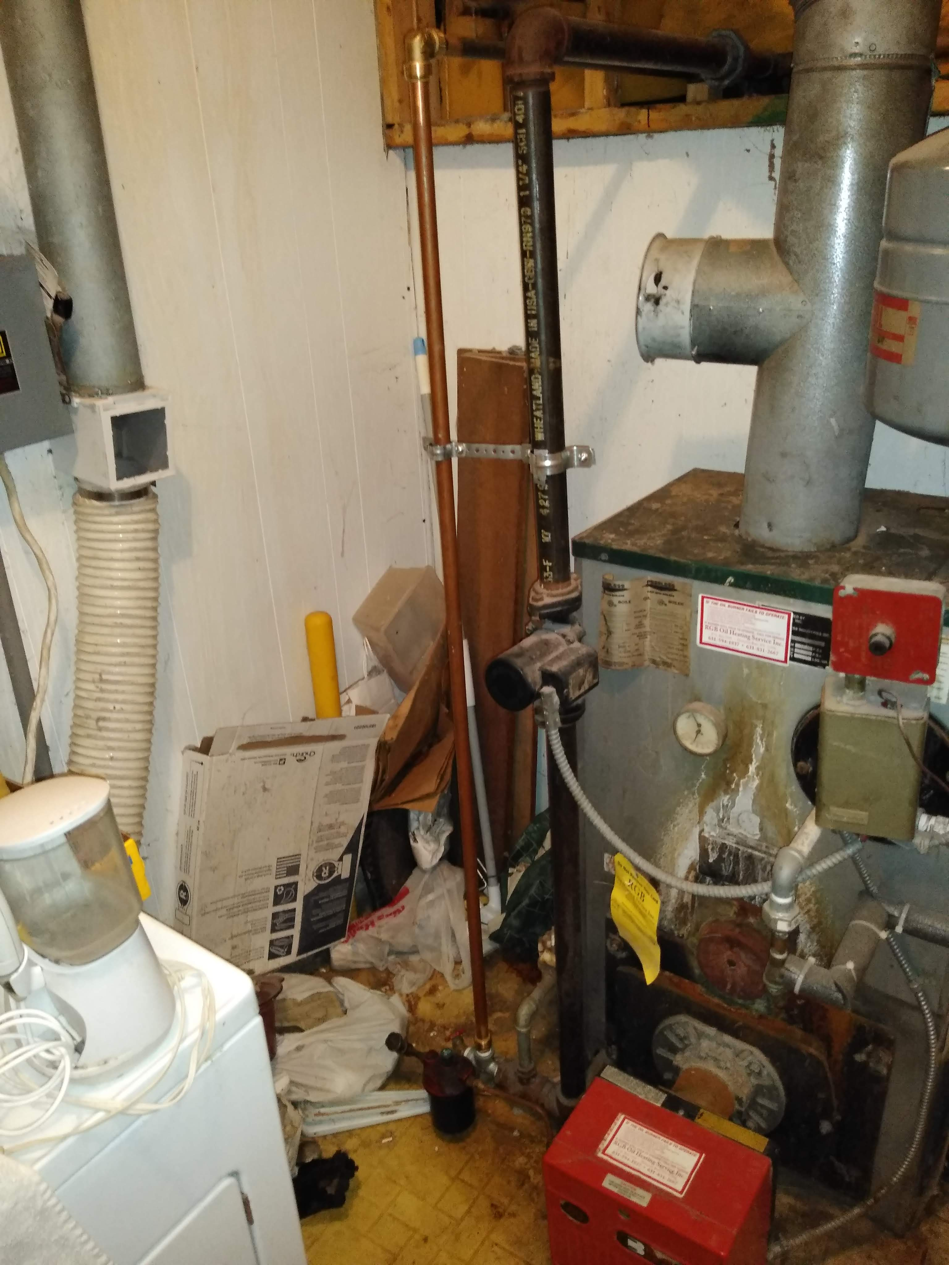
Essentially picture 4 is all of the piping in one picture.
I am "thinking" of removing the flow check and the tempering valve. I am "thinking" that the only thing that inhibits circulation is things in the way, the flow check and tempering valve, so if I remove these nothing "should" restrict the circulator.
Not sure what "keeps the 2 zones separate" means. Picture 5 shows how the radiant loop is tee'd off the mains.
Thanks for the replies.
Ralph
0 -
You say the loop (thermostat) controls "the" circulator. Just one circulator? Or are there two -- one for the radiant and one for the rest of the system? I think I can make out two pumps in the pictures.
Are you sure the radiant circulator is not running?
And I suspect -- although I frankly find the pictures a bit confusing -- that if only the radiant circulator is running, and there are in fact two circulators, the water isn't getting to the boiler at all.
You need to keep the tempering valve, by the way -- radiant systems run at much lower temperatures than regular heat.Br. Jamie, osb
Building superintendent/caretaker, 7200 sq. ft. historic house museum with dependencies in New England 1
1 -
It's really hard to tell how the radiant loop ties into the boiler loop. The piping just doesn't seem to make sense.0
-
That boiler looks like it has serious problems water leaks dripping on boiler/components, scorch marks. Air scoop piped incorrectly, and it looks like the mixing valve is installed wrong. Maybe that failed to the cold.
There was an error rendering this rich post.
0 -
A picture from farther back or a sketch of the system is needed."If you can't explain it simply, you don't understand it well enough"
Albert Einstein0 -
I wasn't going to mention the boiler...Br. Jamie, osb
Building superintendent/caretaker, 7200 sq. ft. historic house museum with dependencies in New England

 3
3 -
The boiler is fine. I installed that 20 years ago.
Picture 3 shows the return to the boiler. The 3/4" copper pipe.
Yes there are two circulators controlled by two individual thermostats.
The radiant loop does not return through the other circulator it is independant. Actually I did have it piped up to return through the other circulator you can still see the lower tee in Picture 5.
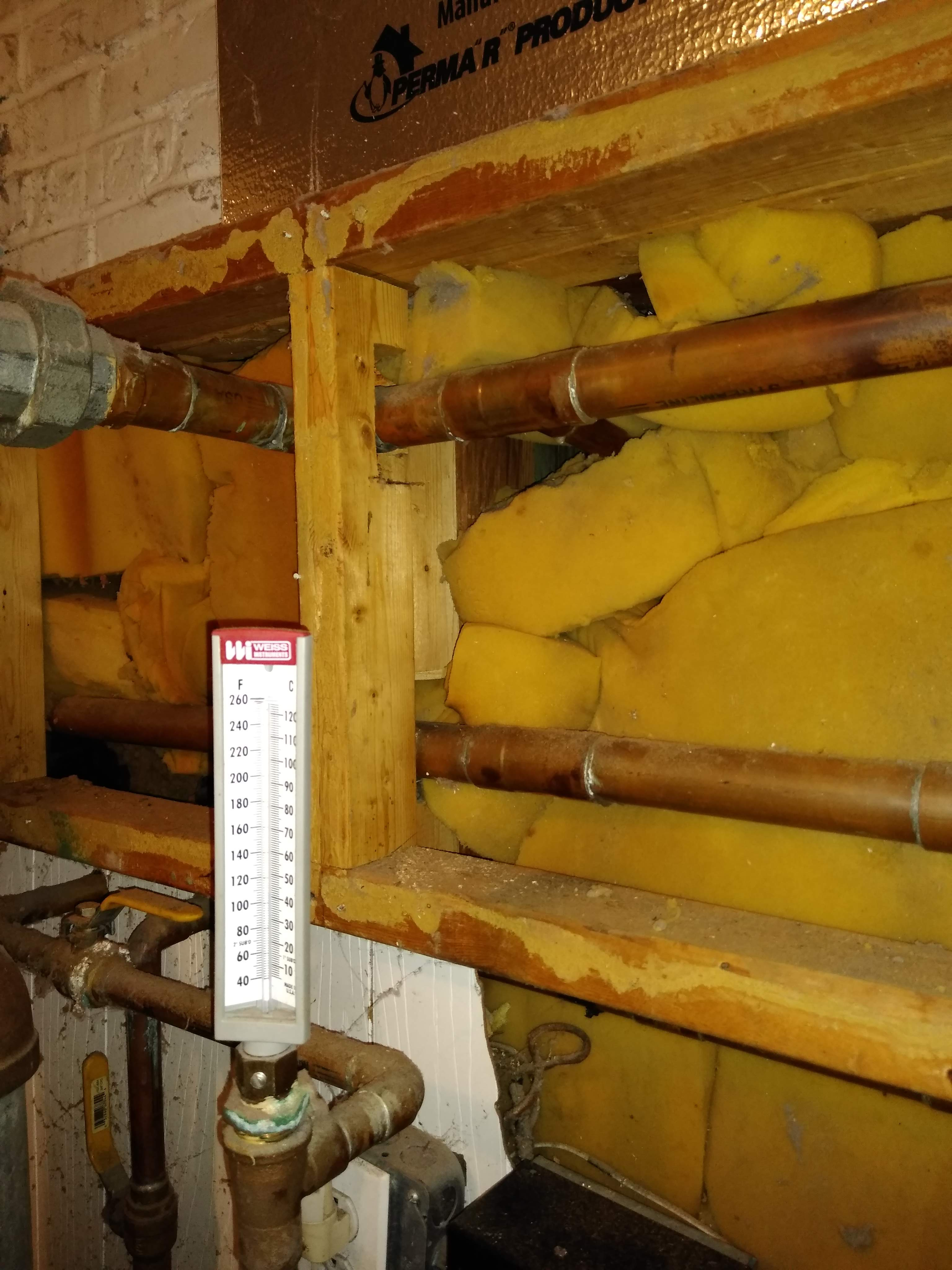
Picture 5 show the supply for the radiant loop teed of the main supply.
Picture 4 shows the other side of the wall for picture 5.
Now let's get something straight.
The problem is:
If the house circulator is running the radiant loop gets hot and function as it should.
If only the radiant loop circulator is running there is no circulation.
Ok I'll keep the tempering valve, what about the flow check?
But if the loop works with the house circulator then nothing is blocking the flow, so I am back to why no circulation.
0 -
OK, I guess you know what all your problems are, and they boil down to just one: when the radiant circulator is running, there is no flow in the radiant loop. When the other circulator is running there is flow in the radiant loop.
Other than the radiant circulator not, actually, running -- which is quite possible. I guess you've eliminated all other possibilities -- since when the other circulator is running you get flow.Br. Jamie, osb
Building superintendent/caretaker, 7200 sq. ft. historic house museum with dependencies in New England 1
1 -
Has it ever worked correctly? Again pictures are hard to tell but my guess is that:
1) the radiant circulator is dead
2) the pumps are hydraulically separated and both need to run in order to provide heat.0 -
mixing valves need a constant flow of hot water from the boiler to operate. Somehow the piping or pumping does not allow this? If all circulators are spinning and moving flow?Bob "hot rod" Rohr
trainer for Caleffi NA
Living the hydronic dream0 -
The circulator is running, at least it has a slight vibration and a slight hum. Plus this is a new circulator, well new to me actually is a used circulator off ebay.
No it has never worked correctly!
I could cut the pipes apart to see if there is flow through the tempering valve. But there has to be flow as the loop works correctly when the other circulator (house) is working. The radiant loop circulator does not need to be working and the loop heats.
Is there/would a larger circulator help?
If I got a 1 1/4" Bell & Gossett circulator do you think that might work?
Picture 1 shows the Flow Check and Tempering valve do you see anything wrong?
Do you see anything wrong with picture 4?
I seem to remember from my past that there is supposed to be a minimum separation between the circulator and the flow check could that be the problem?
I could easily move the circulator to the 3/4" pipe next to the house circulator in picture 3.
Thanks everyone for all of your help I really appreciate it.
Ralph0 -
From what we can see you need a re-pipe of the radiant. But in order to give you correct info. We need more info. Either some pics from far away with all the piping you can get in the pic. or a drawing of the exact piping layout.0
-
What would a repipe be? The radiant coils are embedded in the floor.
Besides it WORKS with the house circulator, so what needs to change, piping wise?
I am really leaning to changing the location of the circulator.
What questions do you have that the pictures do not illustrate?
Picture 1 shows the check valve and the tempering valve the check valve is on the return side the tempering valve is on the supply.
Picture 2 shows the supply piping, the tee in the wall on the supply pipe is supply for the radiant loop.
The lower pipe is the return.
Picture 3 is the return to the boiler.
The black 11/4" pipe is the house return.
The 3/4" copper is the radiant loop return.
I am "think" about moving the circulator so that it is next to the house circulator which is where I would have placed it if I had piped the return as it is now.
Picture 4 shows where the circulator is currently mounted and the check valve and tempering valve piping.
Picture 5 show the supply piping on top and the house return
piping on the bottom. The tee on the return piping is where I had the return connected but changed to the current piping Picture 3.
It works off the house circulator so the piping is correct I remember in my past when I was a plumbing and heating contractor that the circulators came with installation instruction
listing the distance to keep the circulator from any turns, I am googling to see if Grunflos still has those instructions.
Thanks again for the help, just helping me think this through is a big help.
Ralph
0 -
Here are the Grundfos installation instructions:
"We recommend that isolating valves be installed
on each side of the pump. If possible, do not
install elbows, branch tees, and similar fittings
just before or after the pump."
0 -
Pump should pull through the mixing valve for starters.
But have no idea why the hot water would or could even get to the mixing valve without the main pump being on....
Once again just guessing because we can't see how the piping goes in and out of the system. Control wise unless the main house is calling for heat, the radiant floor side is out of luck. Which is the last thing you want with a concrete radiant system...
D 1
1 -
What don't you see re: "we can't see how the piping goes in and out of the system" I stepped through in my prior post.
The piping starts at the boiler and returns to the boiler there is no mystery routing.
If you look at picture 4 you'll clearly see the pull is through the mixing valve. The top pipe is supply the lower return.
I am wonder if the flow check valve should be on the return or on the supply but again the loop works when the house circulator is running so even if the flow check is wrong the loop does work.
Thanks for the replies.
Ralph0 -
Easier if you take better pictures showing the entire system as asked. Marking them up in Paint or Skitch with arrows for flow and descriptions would be even more helpful.
People are trying to help but going back and forth between the pictures and the descriptions is not easy for people to understand.
For example, your very first picture shows what appears to be flow going left to right and the mixing valve shows (to me) the inlet closest to the supply as cold.
We're down to mixing valve, circulator (or related control), and/or piping.
"The circulator is running, at least it has a slight vibration and a slight hum. Plus this is a new circulator, well new to me actually is a used circulator off ebay." Doesn't mean it's 'working', or even the right size (or ever worked).
BTW, the boiler might work, but it is not fine.There was an error rendering this rich post.

 3
3 -
What I clearly see is mud. It looks like that pump is pumping up toward the cold inlet of the mixing valve. Thus pushing into and or away from the mixing valve, thus causing no flow into the radiant system.... The pump belongs on the mixed side of the mixing valve, thus drawing either hot/cold depending on what the mix valve needs for the setting.
D 4
4 -
For a guy that is asking for help, perhaps you could help these fine folks to help you. Your mixing valve is CLEARLY being pumped INTO, contrary to what you think it's doing. The reason we need to see the rest of the piping is to see how the two zones intermingle with each other- the photos available currently do not show that information. If the radiant works only with the other zone running, it's likely just short cycling the radiant water through the mixing valve and never pulling any from the boiler because the resistance is higher in the piping between the boiler and mixer than it is through the radiant- water takes the path of least resistance. Then when the other zone calls, it moves some heat into the piping because it's actually piped somewhat correctly, at which point the radiant is able to grab some and put it to use. We need more photos- plain and simple.2
-
Bob "hot rod" Rohr
trainer for Caleffi NA
Living the hydronic dream1 -
A tempering valve uses the return to cool off the supply, what is it you do not get about how a tempering valve works?
The CIRCULATOR, which is not a pump IS on the mixed side. Calling a circulator a pump automatically eliminates any expressed observation because you obviously do not know what you are talking about.
Yes the tempering valve is being "pumped" into, it needs to have cooler water to "temper" the supply. Again there is no "pumping" there is only circulation.
"If the radiant works only with the other zone running, it's likely just short cycling the radiant water through the mixing valve and never pulling any from the boiler because the resistance is higher in the piping between the boiler and mixer than it is through the radiant- water takes the path of least resistance. "
BUT the radiant loop gets HOT so water has to be pulled from the boiler.
I can not comprehend what more photos would show you, more photos of what? Do you want to see the radiant loop in the floor?
I suppose I could "try" to sketch out the loop but it really would only repeat what you have already seen.
Thanks everyone I really appreciate and need all of the help.
Tomorrow I am going to move the circulator and remove the check valve.
Ralph

 1
1 -
Yeup been doing this for 30 years still can't figure out that pump circulator thingy, push, pull I dunno
NEXTT!5 -
Check the flow arrow of the circulator, just in case it’s installed backwards.
Otherwise good luck to you.There was an error rendering this rich post.
0 -
@Ralphxyz
Your problem would be really simple to solve if you would just draw it out. It is a system and needs to be visualized as such in order to be understood and fixed. I start by drawing any system I am having trouble with.
You have been unable to troubleshoot this yourself because you are just seeing the parts not the system.
BTW, a pump and circulator are pretty much the same thing.
SO BE NICE!!!") "If you can't explain it simply, you don't understand it well enough"
"If you can't explain it simply, you don't understand it well enough"
Albert Einstein 3
3 -
Ralphxyz said:
The CIRCULATOR, which is not a pump IS on the mixed side. Calling a circulator a pump automatically eliminates any expressed observation because you obviously do not know what you are talking about.
Single pipe 392sqft system with an EG-40 rated for 325sqft and it's silent and balanced at all times.
5 -
Circulator pump, how about that? They cause flow too happen by creating a pressure difference from suction to discharge side.
Early on they were called "boosters" if you want to add yet another term for that electro-mechanical device Bob "hot rod" Rohr
trainer for Caleffi NA
Living the hydronic dream0 -
I guess cars and swimming pools don't have water pumps either, they're water circulators.hot_rod said:Circulator pump, how about that? They cause flow too happen by creating a pressure difference from suction to discharge side.
Early on they were called "boosters" if you want to add yet another term for that electro-mechanical device
Single pipe 392sqft system with an EG-40 rated for 325sqft and it's silent and balanced at all times.
0 -
Um... on a car, how about "rotary cooling system energizer"?Br. Jamie, osb
Building superintendent/caretaker, 7200 sq. ft. historic house museum with dependencies in New England0 -
*SIGH*Ralphxyz said:A tempering valve uses the return to cool off the supply, what is it you do not get about how a tempering valve works?
The CIRCULATOR, which is not a pump IS on the mixed side. Calling a circulator a pump automatically eliminates any expressed observation because you obviously do not know what you are talking about.
Yes the tempering valve is being "pumped" into, it needs to have cooler water to "temper" the supply. Again there is no "pumping" there is only circulation.
"If the radiant works only with the other zone running, it's likely just short cycling the radiant water through the mixing valve and never pulling any from the boiler because the resistance is higher in the piping between the boiler and mixer than it is through the radiant- water takes the path of least resistance. "
BUT the radiant loop gets HOT so water has to be pulled from the boiler.
I can not comprehend what more photos would show you, more photos of what? Do you want to see the radiant loop in the floor?
I suppose I could "try" to sketch out the loop but it really would only repeat what you have already seen.
Thanks everyone I really appreciate and need all of the help.
Tomorrow I am going to move the circulator and remove the check valve.
Ralph
At no point, did I refer to it as a "pump", however Grundfos (ya know, the manufacturer) refers to them as a "circulator pump" but what do they know?
The "circulator" you mention is on the COLD side of the mixing valve, pumping TOWARD the valve- not on the MIXED side pulling THROUGH the valve as you've been told several times it needs to be- "what is it you do not get about how a tempering valve works?"
Obviously you've got this whole thing under control and the fools here trying to assist you obviously have no idea what they're talking about, so yeah good luck with your project.
I'll never understand the thought process of a person who is in desperate need of assistance but refuses to help themselves because they already know everything and the very people they ask for help "don't know what they're talking about".
 3
3 -
Bob "hot rod" Rohr
trainer for Caleffi NA
Living the hydronic dream2 -
Ralphxyz
If you want more help, it would be easier for all of us if you just step further back and take a pic, or draw how you have it setup and post the drawing.Tom
Montpelier Vt0 -
Thanks everyone!! I really am "trying" to understand/apply what is being said and I really appreciate everything.
Now to the Tempering valve:
I "thought" I was following the Arrow on the Tempering valve.
That looks to me like Hot on the Right, Cold (return) on the Bottom and Mixed on the Left at least that is what I see from the arrow.
After seeing your comments, Thank You, I Googled Tempering valves and see Hot on the right, Cold (Return) on the Left and Mixed on the bottom, which is not what the Arrow indicates.
So I re-piped it:
Picture 1 re-pipe.
Picture 2 re-pipe.
You will notice that I also re-piped the circulator:
Circulator:
It is kinda working!
I get flow through the tempering valve if I turn the temperature knob but if I leave the thermostat calling for heat in a hour everything cools, the boiler is still hot, but hot supply to the mixing valve is cool, this is with the circulator running, so I guess I'm in a modified same position as I started.
Well I have seen it simulate working but it didn't last.
There might be a frost tonight so it sure would be good to have it working on demand, from the Thermostat.
Oh here is why we call the room "The Garden Room":
Garden Room:
Thanks again everyone, sorry if I came off as a stupid ****.
I really was trying to understand and I figured out how to put arrows in the images.
Ralph
0 -
It looks like you repiped it? I still don't understand how your system is piped with all the snapshots."If you can't explain it simply, you don't understand it well enough"
Albert Einstein0 -
Ok try this:
Red is SUPPLY, Green is RETURN and Blue is MIXED
Circulator
The House Return (black 11/4" pipe) and the Radiant Loop (3/4" copper) are completely separate.
Tempering Valve
Tempering Valve re-piping

Ralph
0 -
The circulator needs to be within the radiant loop. The way yours is piped, flow to the floor stops as soon as the mixing valve sees hot water."If you can't explain it simply, you don't understand it well enough"
Albert Einstein0 -
The valve was piped correctly before. The circ is in the incorrect location in both pictures."If you can't explain it simply, you don't understand it well enough"
Albert Einstein1 -
What are you saying? The circulator is in the Radiant loop.
0


Categories
- All Categories
- 87.7K THE MAIN WALL
- 3.3K A-C, Heat Pumps & Refrigeration
- 59 Biomass
- 430 Carbon Monoxide Awareness
- 127 Chimneys & Flues
- 2.2K Domestic Hot Water
- 5.9K Gas Heating
- 121 Geothermal
- 170 Indoor-Air Quality
- 3.8K Oil Heating
- 79 Pipe Deterioration
- 1K Plumbing
- 6.6K Radiant Heating
- 396 Solar
- 16K Strictly Steam
- 3.5K Thermostats and Controls
- 56 Water Quality
- 51 Industry Classes
- 51 Job Opportunities
- 17 Recall Announcements