Welcome! Here are the website rules, as well as some tips for using this forum.
Need to contact us? Visit https://heatinghelp.com/contact-us/.
Click here to Find a Contractor in your area.
If our community has helped you, please consider making a contribution to support this website. Thanks!
Zone circulator loop reverse flow issue
Options

swedenumberone
Member Posts: 12
I've got a recently installed 6 zone system shown below - was a DIY project by the previous homeowner. The zone's are numbered 1-6 from bottom to top.
I've noticed zone 6 doesn't warm up if zone 4 is running. I think this is happening because with zone 4 active (zone 4 pump is on high, supplies 3 radiators on 2/3rd floors), the water returning from zone 6 flows (zone 6 is on low, supplies 1 radiator on first floor) in reverse (counterclockwise) through the top of the zone circulation loop (hidden in the floor rafters in the photo below, see the design drawing for a better visual) and then back through the zone 6 pump again without passing through the boiler. As soon as zone 4 turns off, zone 6 heats up as expected.
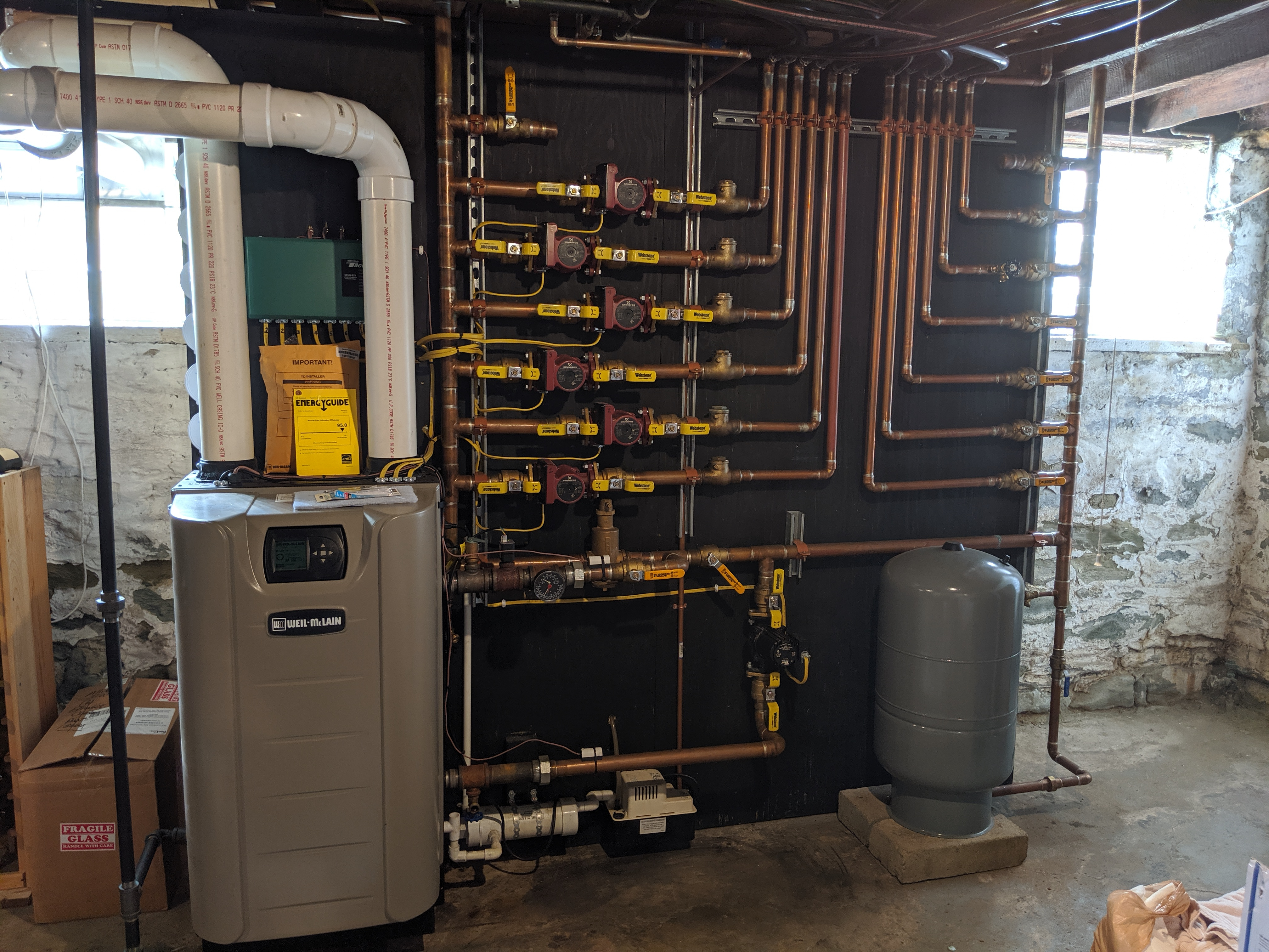


I'm thinking I can fix this by installing a swing check valve in the top portion of the zone circulator loop, but I'm also surprised there wasn't one there in the first place, so wanted to get feedback on whether this is the appropriate solution, or if this would cause me more issues? I'm also wondering if the top part of the zone circulator loop is even necessary - could I just cut it and cap it?
One other thought I had was perhaps the pump settings should be altered (i.e. top 2 zones on high, middle 2 zones and med, bottom two zones on low). Seems like this would still allow for the possibility of reverse flow in the zone circulation loop though, so the check valve seemed like a better idea.
These are the zone pumps:

I've noticed zone 6 doesn't warm up if zone 4 is running. I think this is happening because with zone 4 active (zone 4 pump is on high, supplies 3 radiators on 2/3rd floors), the water returning from zone 6 flows (zone 6 is on low, supplies 1 radiator on first floor) in reverse (counterclockwise) through the top of the zone circulation loop (hidden in the floor rafters in the photo below, see the design drawing for a better visual) and then back through the zone 6 pump again without passing through the boiler. As soon as zone 4 turns off, zone 6 heats up as expected.
I'm thinking I can fix this by installing a swing check valve in the top portion of the zone circulator loop, but I'm also surprised there wasn't one there in the first place, so wanted to get feedback on whether this is the appropriate solution, or if this would cause me more issues? I'm also wondering if the top part of the zone circulator loop is even necessary - could I just cut it and cap it?
One other thought I had was perhaps the pump settings should be altered (i.e. top 2 zones on high, middle 2 zones and med, bottom two zones on low). Seems like this would still allow for the possibility of reverse flow in the zone circulation loop though, so the check valve seemed like a better idea.
These are the zone pumps:
0
Comments
-
What, if anything, is pushing or pulling water around the main loop? That is, if all the zone pumps are off, is there anything to keep water circulating?
I suspect your hunch on what is happening is correct -- that you essentially have two circulating loops: one through zone 4 and the boiler, the other through zone 6 and back around through the crossover pipe. But before one starts fiddling, it would help to dig further and figure out how it was supposed to work in the first place...Br. Jamie, osb
Building superintendent/caretaker, 7200 sq. ft. historic house museum with dependencies in New England0 -
That circulator may have a check installed, unless it was removed, then a label in the box should have been put in the circle on the pump info disc.
You have checks downstream of every pump, not the ideal type and grossly oversized. They may not be sealing tight. should be spring checks or weighted flo-checks ideally.Bob "hot rod" Rohr
trainer for Caleffi NA
Living the hydronic dream0 -
@Jamie Hall It's hard to see in the pic, but there is a black circulator in the boiler loop that pushes the water through the boiler and through the zone circulator loop. It's on as long as the boiler is on.
@hot_rod The zone circulators all have the checks installed. There is no check on the loop that the zones feed from though.0 -
Shouldn’t the common pipe be larger?
There was an error rendering this rich post.

 2
2 -
@STEVEusaPA Assuming the common pipe is the loop, it is larger at 1.5 inches. Each zone is on a 1 inch pipe.0
-
Well let's see here... first off, with checks on all the loops you don't need any more checks. A check valve to prevent reverse flow on the upper pipe might cure the symptom -- but not the problem, so I wouldn't worry about it.
The fundamental problem, as I see it, is that the boiler loop pump can't keep up with the flow in the secondary pumps. There is a flow rate and pressure mismatch there, and without knowing a lot more about the pumps themselves and the head loss/flow rater characteristics of the entire system one really is going to be guessing.Br. Jamie, osb
Building superintendent/caretaker, 7200 sq. ft. historic house museum with dependencies in New England0 -
The cross over pipe should not be there. Put a valve in it or cap like you said.
All those check valves do nothing with that pipe connecting the supply and return together on top.
Why is the valve in between the boiler supply/return partly closed?
D
1 -
I think this is what you are going for? Boiler injects into loop for zone pumps. No need for a valve between the close tee, it needs to be wide open, and it's fine that they are not in the same position. The black boiler pump should not need a check.
I don't see enough of the piping omg the secondary loop, it should not connect, just the boiler pumping into the header with the primary secondary tees.
The main loop piping needs to be sized for the total GPM of all the zones.Bob "hot rod" Rohr
trainer for Caleffi NA
Living the hydronic dream 2
2 -
Depends on whether that crossover pipe is actually part of the primary loop or not -- and I'm not sure we have enough information on the overall layout to tell. If it's part of the primary loop, it has to be there.DZoro said:The cross over pipe should not be there. Put a valve in it or cap like you said.
All those check valves do nothing with that pipe connecting the supply and return together on top.
Why is the valve in between the boiler supply/return partly closed?
DBr. Jamie, osb
Building superintendent/caretaker, 7200 sq. ft. historic house museum with dependencies in New England0 -
True @Jamie Hall I'm just going by the drawing he gave us. The cross over pipe in the drawing should not be there and connected as drawn. That pipe will allow reverse flow to especially the first pump under it, and or take excess flow from another operating pump in the system.
D1 -
To rif off what @hot_rod said.
Open the valve between the boiler tees.
And reduce your zone flow so that it matches the boiler flow. (Sum of all zones should be close to boiler flow maybe a bit higher is ok).
If your boiler supports it, install a system temp sensor on the supply side header before the first zone takeoff, this will compensate for some reverse flow. The boiler will be able to run hotter to compensate for some reverse flow blending. But keep in mind your boiler probably won't like more than a 40 degree delta.
I bet you are way over pumping all those zones. Reduce zone flow by slowing down the circulators and throttling ball valves on the return if necessary. You can use delta T, and space comfort as your guides. Some harder to heat zones may require a lower delta. Some zones may heat with a 30degf delta.
This will increase boiler efficiency by dropping your return water temperature.0 -
@Jamie Hall @DZoro @hot_rod @SuperJ
Clearing up a few questions:
1. The valve between the boiler Ts is fully opened when this issue happens. I opened that to fix the probablem described in this thread:
https://forum.heatinghelp.com/discussion/171345/radiant-heating-zone-migration-leakage#latest
2. I've added a more detailed drawing of the setup below (omitted extraneous stuff like purge valves, expansion tank, etc.) . Sounds like adding a valve at the yellow dot in the drawing (not currently installed) and closing said valve should fix my issue? Any concerns this could cause other issues?
0 -
Ah. There is a perfectly good primary loop. So... one has to wonder what ever purpose was meant to be served by that crossover pipe? Adding a valve there -- and then closing it -- should help a lot.
As @SuperJ said, though, check your flows -- you really do want the flow through the primary (boiler) pump to be at least similar to the maximum flow through your zones.Br. Jamie, osb
Building superintendent/caretaker, 7200 sq. ft. historic house museum with dependencies in New England 2
2 -
This is your fix. ^^^^^You could probably put all the circs on speed 1.Jamie Hall said:Ah. There is a perfectly good primary loop. So... one has to wonder what ever purpose was meant to be served by that crossover pipe? Adding a valve there -- and then closing it -- should help a lot.
As @SuperJ said, though, check your flows -- you really do want the flow through the primary (boiler) pump to be at least similar to the maximum flow through your zones."If you can't explain it simply, you don't understand it well enough"
Albert Einstein2 -
This is a very interesting thread for someone like me who is trying to learn more about radiant heat. Not trying to hijack swedenumberone's thread but could someone please tell me where the "crossover pipe" is?
Thanks,0 -
Either close the valve between close coupled tees, or cap crossover pipe. You can’t have both. I would just close the valve between close coupled tees. Install the system sensor before the first tee to the system pumps. Set up an outdoor reset. Make sure Gpm of the boiler pump equal or exceeds the combined GPM of the system pumps. I would switch all of the system pumps to low speed.
Reconnect the expansion tank to the pipe near the air eliminator.
Gennady Tsakh
Absolute Mechanical Co. Inc. 2
2 -
Thank you gennady, greatly appreciated.0
-
If you close the valve between the tees you are putting the boiler and zone circulators in series. Leave it wide open, use P/S and close the top "crossover" valve
I'd rather see the expansion tank connected to the left of the closely spaced tees, then all circs are truly pumping away.
If located under the separator in that location the boiler circuit is pumping at the tank, aka PONPC.Bob "hot rod" Rohr
trainer for Caleffi NA
Living the hydronic dream0 -
> @hot_rod said:
> If you close the valve between the tees you are putting the boiler and zone circulators in series.
Not really in series, since the crossover allows a decoupling of flow between primary and secondary. The difference in boiler flow and secondary flow could travel across the bridge on top.
@hot_rod 's diagram is the way to go here. And a system sensor as @gennady said will really help the boiler satisfy the temperature requirements will varying flow even if the secondary flow exceeds primary by a good margin.
Keeping the top crossover is not a good fix for a couple reasons (but might be a good interim measure.) Better to close the crossover and leave the valve between the tee's wide open. (and set the secondary flow to reasonable rates).
2 downsides to keeping the top crossover:
1. You won't get an even blended temperature if your secondary flow exceeds your primary (which surely will even with everything on low, unless you throttle the return ball valves as well). Your top zones will pull cold return back thru the crossover if the secondary flow exceeds the primary. (You will get an even blended system supply temp if you block the top crossover and leave the valve between the boiler tees open.)
2. I don't think your piping is big enough to have good hydraulic separation between the primary and secondary loops with the top crossover. This means you will have flow interactions affecting the systems in ways that might be hard to predict.0 -
Hmm, with the valve between the tees closed you no longer have P/S, you no longer have any sort of hydraulic separation? You have either parallel or series piping.
You can only have a primary secondary piping with closely spaced tees, a low loss header, or a hydraulic separator. Really all the same function regardless of the "box".
With the valves between the tees closed the the zone pumps would need to be tied in via closely spaced tees, S&R next to one another. Then the boiler loop is the primary loop, or within the loop I suppose you could say.
Lets say the fixed speed boiler circuit moves 10 gpm, somewhere. I assume it only runs when a zone calls, so two circs at least always run. What % goes around the loop and what % goes to the zone with two circs running. What about all circs running, how much if any goes around the loop.
I suppose if you knew the pressure drop in every piping circuit you could predict the changing flow rates.
I think we all agree a true p/s piping fix is the best, maybe only acceptable fix.
Certainly pipe should be sized to prevent bottlenecks also and the best PONPC established.Bob "hot rod" Rohr
trainer for Caleffi NA
Living the hydronic dream0 -
-
"I suppose if you knew the pressure drop in every piping circuit you could predict the changing flow rates.". Uh huh. You could, assuming you also knew the flow for that pressure drop. There are much better things to do with your time...Br. Jamie, osb
Building superintendent/caretaker, 7200 sq. ft. historic house museum with dependencies in New England0


Categories
- All Categories
- 87.7K THE MAIN WALL
- 3.3K A-C, Heat Pumps & Refrigeration
- 59 Biomass
- 430 Carbon Monoxide Awareness
- 127 Chimneys & Flues
- 2.2K Domestic Hot Water
- 5.9K Gas Heating
- 121 Geothermal
- 170 Indoor-Air Quality
- 3.8K Oil Heating
- 79 Pipe Deterioration
- 1K Plumbing
- 6.6K Radiant Heating
- 396 Solar
- 16K Strictly Steam
- 3.5K Thermostats and Controls
- 56 Water Quality
- 51 Industry Classes
- 51 Job Opportunities
- 17 Recall Announcements