Welcome! Here are the website rules, as well as some tips for using this forum.
Need to contact us? Visit https://heatinghelp.com/contact-us/.
Click here to Find a Contractor in your area.
If our community has helped you, please consider making a contribution to support this website. Thanks!
Hydronics re-design Spacepak - need advice please
Options

RonnieJ
Member Posts: 46
Hi everyone,
I have a self-installed Spacepak high-velocity chilled water system. It works well in the shoulder seasons, but cannot keep up on the hottest days of summer. I am short on air handler capacity.
I really like this system, and don't regret buying it. The system provides excellent humidity control, aspiration distributes even temperatures. ERV provides fresh air year round, silently. The system is quiet and no drafts. Problem is the inability to reach design temperature during hot weather, and electrical usage is much higher than I expected.
Background:
1,500 square foot ranch, full sun exposure. Original R11 walls, unventilated, closed-cell R28 foam attic. 300 sq' addition has R20 walls and a R40 cathedral ceilings. We installed the AC system. I had a blower door test done as part of an energy audit, prior to the spray foam and addition, it was too tight. They recommended an HRV or ERV.
I used load-calc.net to perform a series of manual-J calculations - 70 F @ 88 ambient called for 21,600 BTU, while 70F @ 100 degree ambient was 26,000 BTU. These were with 70 CFM of fresh air. Average of all was two tons of cooling.
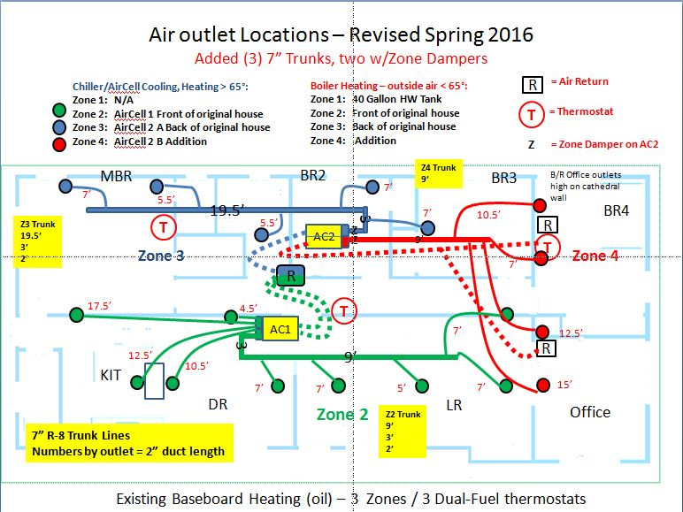
I installed a 3-ton Spacepak SCM-036 chiller, with two Aircell air handlers. Both Aircells use 7" rigid galvanized trunks (R8 insulated), feeding the 2" Spacepak supply ducts. An ERV exhausts main bath air, with the fresh air piped into the fresh air intake directly on the Aircell air handlers. The attic over the original house is conditioned space. It used to be an oven - with the spray foam, it's comfortable up there now.
Challenges:
1.) In hot weather, I can't get the house temp below 74 degrees. I purposely designed it for 70 degrees. If we return from vacation, and we had the air off, it can take two days to reach 74, from 85. My wife likes it at 70 degrees.
2.) Excessive electrical usage. August peak is 1,800 kWh / month greater than my January usage. Chiller runs anytime the Aircells call for cooling - constant in hot weather. To improve performance., the manufacturer's rep had me turn the water down to 33 to 42 degree operating range - this is using excessive energy and increased load on the compressors. We shut if off if gone for more than a week for this reason. A major contributor is the excessive pumping involved - described below. I've read a lot - Caleffi, some of John S's articles, and training on the manufacturer's web site - some of which is also from John. I know it needs improvement.
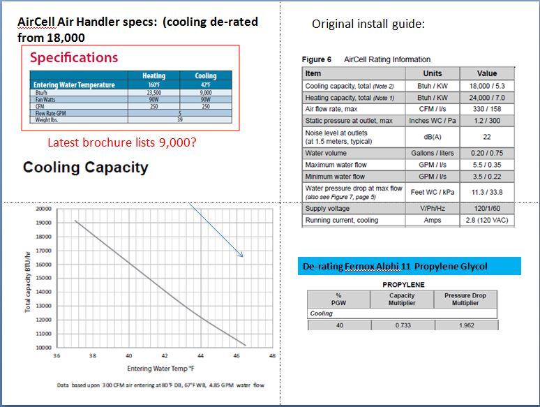
A year or so after purchase, the Aircells were de-rated from 18,000 BTU to 9,000 BTU, under ideal conditions. Due to this change, I am at least 6,000 BTU short of what the Manual-J calls for (24,000), and probably more. I have not been able to get any relief from the manufacturer. I suspect this is a significant contributor to the problem.
When I first installed it, I had questionable advice on the hydronics side in terms of water lines and main pump. I followed the reverse-return design called out in the installation manuals. After the first season, I consulted with a hydronics engineer in FL, and he had me change to a load-match approach with closely spaced Ts. On the air side, I also switched from home-runs off the Aircells to trunk lines, except for one group of four supply lines.
I have good airflow at all outlets, measured with an anemometer. Don't have #s handy. Tech support does not think there is an airflow problem. One Aircells is zoned (bedrooms/addition). The other Aircell is dedicated to the front of the house, living space, faces west. This side gets a lot of solar gain. All of the trunks and supply/return lines are properly air-sealed with foil tape.
Hydronics:
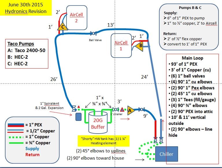
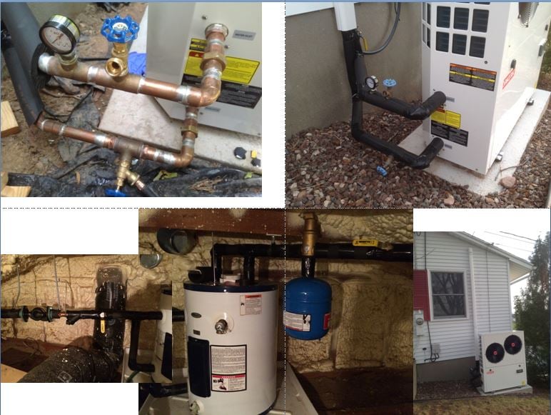
40% Fernox glycol, single loop system. 1" copper off the chiller, converts to 1" Oxygen barrier PEX. Armacell insulated lines. The first Aircell in line has two closely-spaced T's (directly adjacent) - a Taco Bumblebee HEC-2 feeds the Aircell via 1/2" copper, 1/2" copper return is converted to 1" PEX and back into the other Tee. Next Aircell is the same. On the return path, I have an air-scoop with exampsion tank, next in line is a 20-gallon HWH acting as buffer tank. I'm using 1" copper to two 3/4" inlets - and two 3/4" outlet converging back to 1" copper. Flow calcs I've done show this is not a bottleneck - but I'm not a hydronics engineer. On the other side of the tank is a Taco 2400-50 (this is the noise generator) which "pumps away" and back to the Chiller, via 1" PEX again. All of this is in the attic - Chiller is outside. I'll attach diagrams to illustrate. Per advice, I installed a "balancing valve" (full-port ball valve) in the middle of the two Aircells - the theory I was told was to slow the water to allow for greater heat absorption - didn't help so it's wide open.
Questions:
1.) Should I add another Aircell to cover the BTU shortage resulting from the manufacturer de-rating, or replace the two existing with a single 2-ton hydronic unit? The Aircells are discontinued - but I can still source one from a couple of supply houses. These seem to have high-resistance on the coil - 11.3' WC @ 5.5 GPM. I'm leaning to adding a third, unless this is going to drive further inefficiency.
2.) What changes are needed to make this an efficient hydronic design?
3.) Should I switch to a primary/secondary loop arrangement? Would this allow the Aircells to realistically run off the buffer tank for a short time, versus always running the chiller? Attic is 4' vertical on center - no room for a tall buffer tank, BTW. 4:12 pitch roof.
My original calculations, counting Chiller pressure drop, was about 37' of WC on the main loop. I was estimating 10 to 12 GPM on the main loop with the 2400-50 pump, and about 4.5 on the Aircell loops with the Bumblebee HES-2 pumps. I've tried Pumpsim to model this - but this is really beyond my capabilities.
I suspect a primary/secondary design would allow for a downsizing of the main pump - thoughts?
4.) Should or could I get away from needing individual pumps for each Aircell? They don't draw a lot - 90 watts, if memory serves, at setting 4
I've measured the AirCell coil temps as low as 35°, of course the temperature swings with the normal cadence of the chiller range. 4 to 6 degree differential - which I assume means flow ... so I am confused about this. The chiller has a flow switch set at 7 GPM - max flow resistance is 21' WC @12 GPM. I believe flow is sufficient -but have no reliable way to measure it, other than temperature using a laser gun. I've seen designs with a single pump running multiple Aircells - in parallel. If there were zone valves with a single pump/manifold - would that resistance to the pump triple, for three Aircells? With electricity, resistance is additive in series, and reduces in parallel (been a long time since tech school).
I want to re-work the hydronics so I can raise my water temperature back to "normal" ranges - which are above 40 degrees. I'm located in the Hartford, CT area. I would really like to consult with a professional that understands high-velocity systems, but more importantly, hydronics. I checked out the "find a contractor" link, nobody is close. I would appreciate any advice, or for someone to recommend the right person or themselves. Feel free to contact me directly - if the site supports that.
Thanks, Ron
I have a self-installed Spacepak high-velocity chilled water system. It works well in the shoulder seasons, but cannot keep up on the hottest days of summer. I am short on air handler capacity.
I really like this system, and don't regret buying it. The system provides excellent humidity control, aspiration distributes even temperatures. ERV provides fresh air year round, silently. The system is quiet and no drafts. Problem is the inability to reach design temperature during hot weather, and electrical usage is much higher than I expected.
Background:
1,500 square foot ranch, full sun exposure. Original R11 walls, unventilated, closed-cell R28 foam attic. 300 sq' addition has R20 walls and a R40 cathedral ceilings. We installed the AC system. I had a blower door test done as part of an energy audit, prior to the spray foam and addition, it was too tight. They recommended an HRV or ERV.
I used load-calc.net to perform a series of manual-J calculations - 70 F @ 88 ambient called for 21,600 BTU, while 70F @ 100 degree ambient was 26,000 BTU. These were with 70 CFM of fresh air. Average of all was two tons of cooling.
I installed a 3-ton Spacepak SCM-036 chiller, with two Aircell air handlers. Both Aircells use 7" rigid galvanized trunks (R8 insulated), feeding the 2" Spacepak supply ducts. An ERV exhausts main bath air, with the fresh air piped into the fresh air intake directly on the Aircell air handlers. The attic over the original house is conditioned space. It used to be an oven - with the spray foam, it's comfortable up there now.
Challenges:
1.) In hot weather, I can't get the house temp below 74 degrees. I purposely designed it for 70 degrees. If we return from vacation, and we had the air off, it can take two days to reach 74, from 85. My wife likes it at 70 degrees.
2.) Excessive electrical usage. August peak is 1,800 kWh / month greater than my January usage. Chiller runs anytime the Aircells call for cooling - constant in hot weather. To improve performance., the manufacturer's rep had me turn the water down to 33 to 42 degree operating range - this is using excessive energy and increased load on the compressors. We shut if off if gone for more than a week for this reason. A major contributor is the excessive pumping involved - described below. I've read a lot - Caleffi, some of John S's articles, and training on the manufacturer's web site - some of which is also from John. I know it needs improvement.
A year or so after purchase, the Aircells were de-rated from 18,000 BTU to 9,000 BTU, under ideal conditions. Due to this change, I am at least 6,000 BTU short of what the Manual-J calls for (24,000), and probably more. I have not been able to get any relief from the manufacturer. I suspect this is a significant contributor to the problem.
When I first installed it, I had questionable advice on the hydronics side in terms of water lines and main pump. I followed the reverse-return design called out in the installation manuals. After the first season, I consulted with a hydronics engineer in FL, and he had me change to a load-match approach with closely spaced Ts. On the air side, I also switched from home-runs off the Aircells to trunk lines, except for one group of four supply lines.
I have good airflow at all outlets, measured with an anemometer. Don't have #s handy. Tech support does not think there is an airflow problem. One Aircells is zoned (bedrooms/addition). The other Aircell is dedicated to the front of the house, living space, faces west. This side gets a lot of solar gain. All of the trunks and supply/return lines are properly air-sealed with foil tape.
Hydronics:
40% Fernox glycol, single loop system. 1" copper off the chiller, converts to 1" Oxygen barrier PEX. Armacell insulated lines. The first Aircell in line has two closely-spaced T's (directly adjacent) - a Taco Bumblebee HEC-2 feeds the Aircell via 1/2" copper, 1/2" copper return is converted to 1" PEX and back into the other Tee. Next Aircell is the same. On the return path, I have an air-scoop with exampsion tank, next in line is a 20-gallon HWH acting as buffer tank. I'm using 1" copper to two 3/4" inlets - and two 3/4" outlet converging back to 1" copper. Flow calcs I've done show this is not a bottleneck - but I'm not a hydronics engineer. On the other side of the tank is a Taco 2400-50 (this is the noise generator) which "pumps away" and back to the Chiller, via 1" PEX again. All of this is in the attic - Chiller is outside. I'll attach diagrams to illustrate. Per advice, I installed a "balancing valve" (full-port ball valve) in the middle of the two Aircells - the theory I was told was to slow the water to allow for greater heat absorption - didn't help so it's wide open.
Questions:
1.) Should I add another Aircell to cover the BTU shortage resulting from the manufacturer de-rating, or replace the two existing with a single 2-ton hydronic unit? The Aircells are discontinued - but I can still source one from a couple of supply houses. These seem to have high-resistance on the coil - 11.3' WC @ 5.5 GPM. I'm leaning to adding a third, unless this is going to drive further inefficiency.
2.) What changes are needed to make this an efficient hydronic design?
3.) Should I switch to a primary/secondary loop arrangement? Would this allow the Aircells to realistically run off the buffer tank for a short time, versus always running the chiller? Attic is 4' vertical on center - no room for a tall buffer tank, BTW. 4:12 pitch roof.
My original calculations, counting Chiller pressure drop, was about 37' of WC on the main loop. I was estimating 10 to 12 GPM on the main loop with the 2400-50 pump, and about 4.5 on the Aircell loops with the Bumblebee HES-2 pumps. I've tried Pumpsim to model this - but this is really beyond my capabilities.
I suspect a primary/secondary design would allow for a downsizing of the main pump - thoughts?
4.) Should or could I get away from needing individual pumps for each Aircell? They don't draw a lot - 90 watts, if memory serves, at setting 4
I've measured the AirCell coil temps as low as 35°, of course the temperature swings with the normal cadence of the chiller range. 4 to 6 degree differential - which I assume means flow ... so I am confused about this. The chiller has a flow switch set at 7 GPM - max flow resistance is 21' WC @12 GPM. I believe flow is sufficient -but have no reliable way to measure it, other than temperature using a laser gun. I've seen designs with a single pump running multiple Aircells - in parallel. If there were zone valves with a single pump/manifold - would that resistance to the pump triple, for three Aircells? With electricity, resistance is additive in series, and reduces in parallel (been a long time since tech school).
I want to re-work the hydronics so I can raise my water temperature back to "normal" ranges - which are above 40 degrees. I'm located in the Hartford, CT area. I would really like to consult with a professional that understands high-velocity systems, but more importantly, hydronics. I checked out the "find a contractor" link, nobody is close. I would appreciate any advice, or for someone to recommend the right person or themselves. Feel free to contact me directly - if the site supports that.
Thanks, Ron
Energy Kinetics EK, Goodman GSXC72400, SpacePak ESP 2430J
0
Comments
-
Does this chiller stay on all the time and run constantly at full capacity? Not farmalier with the chiller does it modulate? Or is the chiller cycling on water temp? That would be my first question. Also was the chiller and AHUs selected with 40% glycol which can hinder .capacity?
I would start with a through analyasis of the chiller. The chiller may not be the problem but I would start their and see where it leads.
Not crazy about the way AHUS are piped. First ahu is raising supply temp of water to the second ahu. I would repipe so both ahus get the same water temp.
But I would analyze the chiller first. It has enough capacity or not. Then move on to piping and AHUS
0 -
Hi Ed - thanks for your suggestion. The chiller has two compressors that run independently - it’s rated for 36,000 BTU - so should be up to the task. It makes 33 degree water with both compressors running. I believe it is modulating - it will start with both compressors on to chill to the low set point and then one shuts off- temp climbs to the differential - when it hits 43 both compressors are engaged and then it pulls it back down to 33. Then the other compressor shuts off. It’s got intelligent controls and runs independently of the AH - if there is a call for cold or hot water, it’s either on or off. It will not engage the compressors unless the water temp is out of range.
In the shoulder seasons - it runs for 10 minutes or so and then shuts off for a while. These temps are way lower than should be necessary. I don’t believe the chiller is the problem - I do think it could be not enough cooling capacity reaching the AH’s
The series approach is my second - the water temp only drops a degree or two max between the two air handlers. The original design fed both air handlers prior to return water entering the stream - it did not run well - but the feed lines were a lot longer, and I’m not sure if the total dynamic head was more than the bumblebees could overcome. I am thinking a manifold with dual feeds would be better - I need someone with experience to help with the calculations so I only need to redesign this one last time.
Cheers,
RonEnergy Kinetics EK, Goodman GSXC72400, SpacePak ESP 2430J0 -
can you tell the water temps in and out of each air handler?
and same question for the air temps, both return, and supply
if you're cycling 33/43 water at the chiller,
why isn't, where is the transfer at the AHs?known to beat dead horses0 -
Hi Neilc, Thanks for your question. We're not in cooling season, so I can't provide modern numbers. The history was that I first installed using a reverse return flow design - meaning the cold water intakes both were fed prior to the returns, and with the Aircell 2" feeds right off the air handler to the supply orifices in the ceiling. I changed main pump to get past flow errors - too much total dynamic head. I also added individual bumblebee pumps to feed the air handlers. This was all based upon advice I was getting from the rep. This is when the temps in this chart were taken. Next, I installed the 7" trunk lines, and added a few extra 2" supplies. This improved the system performance -but still have the issues I've posted about. Also - these readings are from an inexpensive laser reader - $30 or so. I've read that flat black tape helps with temp reading - it was hard to get consistent measurements.
These readings are the current pipe design, but prior to the 7" trunks being installed. I have taken readings since, but I had not saved them. Take a close look at the chart please - the glycol supply and return headings are measured at the air handler supply and return right at the coil. The coil temp is at the fins inside the unit. The air supply and return temps -I picked the best case typically - so the outlet at the ceiling, and the return airbox in the central hallway. Please note - I was experimenting with water temperatures at the chiller - note the blue headings showing outside temp, and chiller temp range. The bottom one was where I kept the temp in a tight range to reduce fluctuations to get a good bead on the measurements -it's now set to 33 to 42. I need a hot day to measure again - it's only 65 out today. These are from 2015.
I would like to see a greater temp differential - I was told it was pretty good - but to be clear, I am not an HVAC tech, if that's not already painfully obvious ;-)
Thanks,
RonEnergy Kinetics EK, Goodman GSXC72400, SpacePak ESP 2430J0 -
I see two major things:
1. The air cells are rated for 9000 btus cooling. Regardless of what earlier literature may have said, that's clearly what their capacity is. And keep in mind, that's @ 80* db, 67* wb, not 70* db, 57* wb. The capacity would probably be 75%, or less, at those temps. You simply need another indoor unit. Whether it's another air cell, or ductless wall or floor mount, you need another unit.
2. As Ed pointed out, the indoor units are now piped p/s series which is limiting the second unit down stream. I'd go back to either direct or reverse return on the piping supplying the units. You already have hydraulic separation between the system and the chiller with the buffer tank. There's no need or advantage to have secondary/tertiary piping.Bob Boan
You can choose to do what you want, but you cannot choose the consequences. 1
1 -
Hi Bob,
Thanks for your feedback. I did plan to add another Aircell - it will be easy enough to integrate it. Do you think the lack of air handler capacity is driving excessive energy use? Besides not hitting the desired temp, the electric bill is killing me. Prior to this, we cooled out house with a built in 12,000 BTU wall unit and a couple of 5,000 window units - it clearly was not ideal, but the electrical cost was insignificant.
On your second point - do I actually have hydraulic separation, with the buffer tank the way I have it plumbed, in series?
Cheers,
RonEnergy Kinetics EK, Goodman GSXC72400, SpacePak ESP 2430J0 -
" " A year or so after purchase, the Aircells were de-rated from 18,000 BTU to 9,000 BTU, under ideal conditions. Due to this change, I am at least 6,000 BTU short of what the Manual-J calls for (24,000), and probably more. I have not been able to get any relief from the manufacturer. I suspect this is a significant contributor to the problem " "
/\ This /\ (?) and glycol.
you're showing some decent temp deltas,
if anything, too cold (for me), I wouldn't expect you'ld need water in the 30s., or air at 45.
Have you tried slowing water flow down at the coils?
might be worth a shot.
it can be hard, inaccurate, getting temps with the laser, ideally you'ld be reading gages on both sides of the coils, and I have fast acting chef thermometers in my air supply and return
45 SA ? have the wife sit under that.
Are the difussers aimed to mix well into the rooms?
Can you feel gentle air movement while air conditioning?
Fan speed duct pressure adjustable?
Which brings us back to glycol, and that derating above.
You likely need that 3rd AirCellknown to beat dead horses0 -
I agree with @Ironman that AHU capacity is your biggest issue.
The MFG derating to 9000 btu is killing you. Also 40% glycol will mess thing up if not taken into consideration.
I would repipe into a true primary secondary. see attached. I would pump the chiller at 6gpm on the main loop.
The ahus you may be over pumping and affecting heat transfer. Try slowing the pumping just for fun and see what the air temperatures do & add another ahu.
1" mains and 3/4 branches to the ahus is what I would do0 -
Disregard that drawing something went haywire.0
-
-
Hi Neilc - that is an interesting idea. I just recently read, on this site, a discussion on the topic of flow vs. heat transfer - and in theory faster is better, except for some real-world examples. My memory is poor - I'll need to go search for that.
I did try slowing down the water in the main loop (using the "balancing" valve) - which at that time did not help -we tried that with incremental settings. If I close it too much, then as expected, it causes flow errors on the chiller.
On the individual AH pumps, I've tried all four speed settings on the bumblebee. The gpm value in the chart are from the LED screen - I've learned from this site and from Taco that those are not a reliable indicator of actual flow. I just powered it up - the bumblebees are on speed setting 4 -drawing 40 watts at a reported 11.5 gpm. (I had mentioned 90W in an earlier post -love these little circulators). In reality, I think the flow is at 4.5 gpm - based upon pump curves and the Airell specs - WC vs. Flow.
All of my past testing (3 years now) has shown the best cooling performance at pump speed 4.
This is why I would like to hire a professional to perform some design calculations - unless the answers are obvious to you experts. I'm not able to get anywhere. I'll add an AH, but I want to be sure the piping is designed to deliver the best results.
Thanks much,
RonEnergy Kinetics EK, Goodman GSXC72400, SpacePak ESP 2430J0 -
Hi Ed, thanks for the diagram! Neilc - I didn't answer the outlet air question - I have excellent even air distribution - I'm convinced the problem is on the water side. The smoke test that Mestek/Spacepak has on their site - or wherever I saw the aspiration video - it really works like that. The air temp is very even throughout the entire house - assuming T-Stats are set evenly for each zone. Common return - so central hallway is the mixing area.
When designed, I did take into account the de-rating for 40% glycol. With the original 18,000 BTU capacity rating x 2, I had a whole extra ton of capacity over the Manual-J to cover these variables, I thought I was covered. Adding more AH will correct for that.
Ed - I realize that is a simple drawing - would that be a pre-manufactured manifold, or can I just make one up? What pipe size would make a good manifold? Since I have the 1" PEX already, I would like to reuse it - the connections to the AH are 1/2" copper - which is the natural restrictor for the zone piping. I'm assuming keeping 1" to the bumblebee would present least TDH. Do you agree? Are the pumps better near the AH, near the manifold, or does it matter?
We crossed posts - I have slowed down the water flow - doesn't help. I need a minimum of 7 gpm to satsfy the chiller integral flow switch. I would love to replace the 2400-50 with a more efficient pump - I purchased that. it's a beast, (loud)
I've drawn this up - is this what you mean? Would it be better if the manifolds were on either side of the buffer?
Thanks for the ideas,
Ron
Energy Kinetics EK, Goodman GSXC72400, SpacePak ESP 2430J0 -
Neilc - also - fan speed is adjustable - is an ECM -I have the fan speed on max. No idea what the duct pressure is - but all my ductwork is within design rule criteria.
Incidentally, the whole time I was drawing that picture - 20 to 30 minutes - I had zone 3 running in cool mode. I left it on without thinking - realized it after I posted and went to shut it off. Originally was set to heat at 69 degrees and room temp where the stat is was 69. Two air outlets in that room. Changed it to cool, 67 degrees, turning on the AC for that zone. Ran 20 to 30 minutes - but did not drop the temperature a single degree. It's 60 degrees outside. Chiller water temp was in the 33 to 42 range. This doesn't make sense to me. That T-stat is controller both boiler and AC -so baseboard was not on.
If you look at my Air Outlet Diagram earlier in the post, the single Blue zone 3 is getting all 9,000 BTUs, or whatever the actual delivery is factoring in glycol, etc.
Importantly, I did not close the MBR door to the kitchen (weird layout) or the hallway door to the front half of the house, to isolate it. A zone damper keeps Red Zone 4 from getting any cooling during this accidental test. There are 7" ducts coming off that Aircell for each zone. To me, this speaks to something other than AH size. I did not measure the Aircell temps. Unless I should repeat the test with door to the kitchen closed, and the hallway door to the front of the house closed - that would have been a better test. I know this is just noise, but thought I would share it. I would expect cooling to take effect immediately, and maybe drop a degree in that time-frame. MBR is on the Northeast side of the house - no sun at this time of day (6:30 to 7:00 pm).
Energy Kinetics EK, Goodman GSXC72400, SpacePak ESP 2430J0 -
Couple things.
Can you post return and supply temperatures on the Air Cells and Chiller. Return water temp is what matters to chiller output and capacity. Air cell capacity can be increased by adding airflow if that’s possible, but noise will go up and humidity removal will be reduced.
Flow rate can be determined by differential pressure (total head) across the pump and then looking at the pump curve
If you have excess chiller capacity, you could just add some stand along floor mount or wall mount units (look like minisplit indoor units) or even concealed duct units.... or add another air cell. Aparrently they de-rated the units. 160F water temp is rediculous when they are meant for condensing boilers or reverse cycle chillers. 140F or 130F is better.0 -
Hi Mikeg2015 -see my earlier chart I posted for this information from 2015. I need to re-measure these. I can go do that now if you think it makes sense to - meaning meaning it's 60 and dropping fast outside temp. Inside is 69 degrees - I'm not sure how cold an AC system can go. The Aircell differential has been 4 to 8 degrees, but usually I see about a 5 degree differential. I have not documented the chiller. I can easily measure that - the fill and drain faucets are exposed. If a test at any outdoor condition is valid, I'll go run the test now. Please let me know.Energy Kinetics EK, Goodman GSXC72400, SpacePak ESP 2430J0
-
I've had this nagging feeling that the flow through the Aircells is the issue. Spacepak makes a traditional air handler (these units are compact, plastic housing) - that has much lower pressure drop - which would allow greater flow. That's why I asked the question about switching out the Aircells for a traditional water based AH.Energy Kinetics EK, Goodman GSXC72400, SpacePak ESP 2430J0
-
Yes you manifold will work. 1" will carry 8 gpm and your chiller needs 6 so that is ok. AHUs may have 1/2" connections but I would use 3/4 right up to the ahus. Your looking to get 3/4 ton out of each ahu so the flow would be about 1.5 gpm which would max out 1/2" now isn'tthe time t cheat0
-
Hi Ed, I've posted specs for the AH and Chiller. The AH wants 4.85 gpm to meet it's 9000 rating @ 42F water. The chiller wants 10 gpm to meet it's 26,000 rating @ 44F water. I know these are all variable - but if 1" is good for 8 gpm, that is barely over the chiller minimum flow of 7 gpm. Where are you getting the 6 gpm, respectfully asking - is this based upon BTU? I'm looking at the latest version of the chiller manual -it says they want 10 GPM. "Each SCM Heat Pump has a recommended flow that should be
maintained during all times of operation. For the SCM-036, the
recommended flow is 10 GPM, at which the head loss through the heat exchanger is 15.8 ft. WC, 6.8 PSI or 47 kPa. These head loss values are based upon pure water, see Figure 12 for multipliers to correct for various concentrations of anti-freeze solution.". The multiplier for head loss is 1.5 for propylene glycol - I'm using Fernox Alphi 11. 15.8 x 1.5 = 23.7', not counting anything outside of the chiller. The original thinking on 1" pipe was that is the size that the chiller connections are. At the time, I was getting advice from the rep, and there was no discussion of going with larger pipe. The new manuals have a lot more hydronic information in them.

Energy Kinetics EK, Goodman GSXC72400, SpacePak ESP 2430J0 -
wrong second picture - here are the chiller specs

Energy Kinetics EK, Goodman GSXC72400, SpacePak ESP 2430J0 -
Hello Mikeg2015,
I ran a test on Green Zone 2 -front of house.
I'm not sure how accurate this Ryobi laser tool is - but it's all relative.
Ambiant outdoor air temp = 52 F
Chiller - set to 32-42 F range - I did not watch it, but suspect at his outside air temp, only one compressor may have been on.
Chiller out: 30 F to 31 F (brrrrrr),
Chiller in: 37 F
Aircell In 55 F
Aircell Out 60 F
House zone 2 ambient 70 F
Various supplies: 52, 53, 54, 54 F supply
Return Grill air temp: 68 F
Thanks,
RonEnergy Kinetics EK, Goodman GSXC72400, SpacePak ESP 2430J0 -
Chiller fluid leaving temp is 37°, but that Aircell in temp of 55°, is that fluid entering temp? Are they still piped in series? Is that the entering temp of the second Aircell?0
-
Normally chillers run at 2-2.5 gpm/ton is normal water flow. Maybe space pac runs higher flow, don't know but if it's a 3 ton chiller water flow should be 6-7.5 gpm based on that. Glyclol may be slightly higher. It's all what they design for.
The only way to really know flow is to install "circuit setter" balancing valve and read the actual flow with a flow meter
2 gpm/ton = a 12 degree td on the chiller at full load
2.5 gpm/ton=a 10 degree td/ton at full load.
The stuff I am throwing is general used accepted practice. Maybe space pack is different.You can reduce the pipe size and use a bigger pump to get the flow but that usually leads to a dark place if you go to far astray.
If you need 10 gpm on the chiller with glycol then you may need 1 1/4" pipe. If the ahus need 4.5 then the 3/4 is maxed.
Dosen't mean the smaller pipe cant work but in my mind if you cheat a little on one thing....fine. skimp here skimp there the problems become cumulative
0 -
Ratio - the chiller is producing 30 to 31 degree water - I measured the first stop at the first Aircell (air handler). The Aircell has 1/2 copper core connections -they are wrapped in rubber insulation - I did my best to get a read on it. The input was 55 and the output was 60. I don't know why the outside pipes read so much higher - it's always been that way. In the past, when measuring the core, it's a degree or two above the chiller output. I can't easily measure the core tonight - need to pull the covers - can repeat in the morning. the pipe is copper 1" to Pex 1" - runs 10 feet up the house directly into the attic, 90 - runs horzontally direct to the air handler. Note the air handler take-offs are 90 degree Ts - with a pump pulling the water off the main line. The air temperatures posted show air 15 degrees colder than the house temp - so I know the air handler is getting cold water. the attic is 70 degrees right now -just like the house. It has 5" of blown in cellulose in the attic floor. I left it there when we insulated the ceiling rafters with spray foam.
Ed - thanks for the explanation. The pipeing is all 1" today - copper near the chiller and between the airscoop/BT/pump, then back to pex to get back down to the chiller. There is no 3/4. I know Pex has less flow capacity than copper of the same size. Perhaps this is also part of the issue.
Thanks gents,
RonEnergy Kinetics EK, Goodman GSXC72400, SpacePak ESP 2430J0 -
1" pex is not 1" copper. 100 feet of 1" pex at 8 gpm, 40 degree, 40% glycol has a pressure drop of over 16' of head. What is the pressure drop of the Chiller? That has to be added to the drop of the pex to size your chiller pump. Get a good clamp on temperature gauge like the type that is used for take superheat or subcooling and check the deltas on the water going in and out the AHs that will tell you the absorption of the AHs. if the deltas are too low you are not removing the BTUs from the water due to low air flow or the heat exchanges in the AH are too small. If the deltas are too large then you are not pumping enough of water to the AHs. Start there before you repipe every thing and buy new equipment. I agree with some of the other comments if the issue is that the AHs are too small adding additional room mounted units may the simplest solution to your capacity issues.0
-
Hi @Handyman 242 - "For the SCM-036, the recommended flow is 10 GPM, at which the head loss through the heat exchanger is 15.8 ft. WC, 6.8 PSI or 47 kPa. These head loss values are based upon pure water, see Figure 12 for multipliers to correct for various concentrations of anti-freeze solution.". The multiplier for head loss is 1.5 for propylene glycol - so 23.7 + 16' you called out for pex is 39.7 feet. My past calculations were in this range - what I did not account for was flow rate on the main loop.
I've been working with the Taco HVAC System Solutions application to see if I can get that number lower. A primary/secondary approach will allow me to to shorten it, and I'm seriously considering up-sizing the piping in the primary loop to find some relief. I'm not buying anything until I am certain the design is right ;-)
Thanks,
RonEnergy Kinetics EK, Goodman GSXC72400, SpacePak ESP 2430J0 -
Hi everyone, I've got a few questions related to indirect tanks and heat exchanger choices.
The first picture below (courtesy of the Taco HVAC Solution application) is a rough representation of the (re)design under consideration - adding a third Aircell air handler and changing to a primary/secondary loop arrangement. Per manufacturer specs, these air handlers produce 9,000 BTU @ 4.8 gpm @ 42 degree water. Each AH has 11' of head across a 1/2" piped coil at rated flow.
The chiller would be on a primary loop with 40% glycol. I want to make the secondary loop supporting the air handlers plain water. This would avoid the BTU derating and extra head that comes with glycol. My current design is all glycol and I cannot meet the low requirements with my existing pumps unless I change to water. The attic is sealed with closed-cell foam - I am not overly concerned about freezing - I have a generator to keep the house functioning on oil heat in a power outage - I could always drain the secondary if freezing temps in the house were unavoidable.
To achieve this separation, I'm looking at a an indirect water tank with integral coil. Specifically, the Lochinvar Squire SIT030 fits vertically in the 40 to 42" of vertical space I have available in the conditioned space attic, and the capacity meets or exceeds the minimum size called for. I like this model as it has 1" connections on all fittings - I'm avoiding models with 3/4" secondary connections - I intend to have a manifold/header on the secondary supply/return.
I'm wondering how efficient the heat transfer in a coil exchanger in-tank would be? Acceptable? Any concerns with this approach versus an external plate exchanger? The benefit of the internal coil tank is that the primary loop and heat exchanger would be serviced by a single main pump, and the secondary flow though the tank would be provided by each individual pump on the air handlers.
The second diagram is from a Spacepak / John Siegenthaler brochure - it discusses using an external plate exchanger. I've seen other training slides (also Siegenthaler) where a seperate pump is required for the storage tank to secondary plate exchanger flow, in addition to the secondary loop pump. I believe it was left off for simplicity sake in the sales brochure.
I understand that plate exchangers are likely the more efficient type, I have one on my EK1 indirect, but for this application, the coil approach seems to offer a simpler design.
A second area I would like to ask about is where to physically place the pump on the line feeding the Aircell. Currently, I have a Taco Bumblebee HES-2 pump coming off a twin-T from the main loop (illustrated in previous posts above) - it comes off the main loop with 1 foot long, 1" PEX feeding the pump. I exit the pump with a 1/2" flange, with two feet of 1/2" flexible copper connecting to the 1/2" coil on the air handler. The return converts from 1/2 copper into 1" PEX before it gets back to the second Tee connection -about 3 feet long. I've been told the pump is beating it's head against the 1/2" (sort of a pun there). In the new design, I would come off the supply manifold with 1" PEX (or something else) I could place the pump closer to the manifold - pumping toward the AH. The Air Handlers are probably going to be about 15' from the tank. I've been told it would be better to make the output of the pump 1", and transition to 1/2" further away, so the pump is not pumping into that smaller pipe side so close by. What would be best?
I would appreciate your thoughts.
Thanks,
Ron

Energy Kinetics EK, Goodman GSXC72400, SpacePak ESP 2430J0


Categories
- All Categories
- 87.7K THE MAIN WALL
- 3.3K A-C, Heat Pumps & Refrigeration
- 59 Biomass
- 431 Carbon Monoxide Awareness
- 127 Chimneys & Flues
- 2.2K Domestic Hot Water
- 5.9K Gas Heating
- 121 Geothermal
- 170 Indoor-Air Quality
- 3.8K Oil Heating
- 79 Pipe Deterioration
- 1K Plumbing
- 6.6K Radiant Heating
- 396 Solar
- 16K Strictly Steam
- 3.5K Thermostats and Controls
- 56 Water Quality
- 51 Industry Classes
- 51 Job Opportunities
- 17 Recall Announcements