How Do I Connect This Wire?

I have made several wiring diagrams in the recent past in order to help others solve a problem they encounter. Some are simple, others are more complex. Digital electronics and technology are built into just about everything from our cars, to our front door locks and cameras, to the thermostats that we use to keep us comfortable. I think that stuff is great, but I would not know the first thing about a chip or a diode or a triac or transistor or any other pieces of these electronic wonders, gets put together. I am strictly an analogue relay and switch kind of guy. So when it comes to HVAC controls and how to make them work, I break it down to the simplest common denominator. What gets turned on and what gets turned off based on what you are asking the equipment to do for you.
The NEST thermostat is one of those marvelous pieces of technology that has no contacts, switches or relays inside it, but somehow it opens and closes circuits on analogue type HVAC equipment just like a conventional set of contacts on the older thermostats, in order to turn a gas valve on and off, or a compressor contactor to energize and close a set of contacts or to de-energize when we get to the proper comfort level.
A fellow wallie
@MikeAmann, gave me this great idea to post a discussion with some of my wiring diagrams after one of my ideas helped solve an issue for him. So here it is,
As I post different solutions to common problems and maybe some rare occurrences too, I will copy and paste them here. And I am going to start with one of
@pecmsg's favorite subjects, the one that seem to come up more often over and over The Dreaded C wire for the NEST thermostat and other smart thermostats.
Edward Young Retired
After you make that expensive repair and you still have the same problem, What will you check next?


Comments
-
When the Nest first was introduced (Before google acquired NEST) I found that there were some problems on some devices. The first one was a Taco Zone Valve 570 series. Without going into details this is how I fixed it.
Before Nest Thermostat

After Nest Thermostat showed E72 error

I added this isolation relay with a separate transformer. (Green) See how the contacts on the relay do the job of the old T87F thermostat contacts. It is the simplest fix for all kinds of incompatibility issues with any smart thermostat.
Here is a comment made by a Taco Tech Support guy years later. It seems that they fixed the Nest or upgraded the software over the internet.Edward Young Retired
After you make that expensive repair and you still have the same problem, What will you check next?

 5
5 -
When you apply new technology to the older analog , expect some issues ...
There was an error rendering this rich post.
3 -
It is tough trying to find old series 10 wiring diagramsThis was the most common device of the series 10 era. The 90 second safety stack relay.

From someone with a Timkin Boiler (was upgraded with a Carlin burner) wanted to find the original wiring diagram.
WOW... You have a Honeywell series 10 (3 wire) switching relay to operate the circulator. R132A Series 10 controls employed a holding circuit in order to get a long enough differential from the Bimetal thermostats. W>B would pull in the relay. Since the Bimetal quickly warmed up and the contact opened there was a second contact connected to W>R that held the circuit for more temperature range, in order to eliminate short cycling. This is a classic control.See the holding circuit in the Red oval

Although difficult to see, this might be the diagram used to originally connect your heating system's controls

I reworked this diagram:

What does the thermostat look like?
From this discussion:EDIT: More series 10 wiring is found here.
Edward Young Retired
After you make that expensive repair and you still have the same problem, What will you check next?
1 -
ZC and ZR used according to the original Honeywell wiring diagram will cause a loss of power to the Second Zone's switching relay. That may be a problem for some smart thermostats. Here is my Re-Do with the same result but the power to the switching relay is not interrupted.
See if you can find the changes?
The original is figure 11 of these instructions: https://s3.amazonaws.com/s3.supplyhouse.com/manuals/1350895640264/84101_PROD_FILE.pdf
Edward Young Retired
After you make that expensive repair and you still have the same problem, What will you check next?
0 -
HydroStat recovery software will increase temperature every 30 minutes
Some think that is too long for their needs
This is the one that started the idea for this discussion, HydroStat has several controls that have optional outdoor reset. This works great when maintaining a given set point temperature. If, However, you wish to lower the temperature at night for sleeping in a lower temperature room, the recovery time in the morning can be over 2 hours with the pre-programed boiler temperature boost after 30 minutes. @TerrS wanted that timing to be faster, so this is the two stage thermostat idea I offered"Here is the latest diagram based on the 4200a control:

1. The concept is to fool the HydroStat control to get a higher boiler temperature during setback recovery. (at 6:00AM and 3:00PM)
2. The HydroStat will provide a higher boiler temperature if there is a call for DHW. (so we will use that feature at 6:00AM and 3:00PM)
3. The thermostat you have has the capability for 2 stage heat operation.
4. Your thermostat will automatically select stage 2 operation whenever the set-point (the desired temperature) is more than 1° higher than the room temperature.
5. This happens whenever there is a change from set back to normal set point (desired temperature). For example changing from 64° to 68° is more than 1° higher
6. By operating a RIB relay with stage 2 from one of the thermostats, the relay contacts can tell the boiler to make DHW with higher temperature water. (but we will operate the CH circulator pump)
7. Once the room temperature reaches 67° (or the DHW demand reaches 45 minutes) the stage 2 relay will drop out and the boiler will automatically revert to ODR mode.
8. You must program your 4200a to accept the stage 2 as DHW demand for this to work. (it should come that way from the factory)
9. You must connect the DHW/Zone 2 circulator wire to your existing circulator with a jumper or wire nut at the 4200a control (see triangle note 5)Edward Young Retired
After you make that expensive repair and you still have the same problem, What will you check next?
4 -
Weil McLain Steam boiler with NEST, No Relay needed
FROM:
https://forum.heatinghelp.com/discussion/188201/adding-c-wire-to-weil-mclain-steam-boiler
Here is the updated wiring diagram if you feel competent to rewire the low voltage exactly in order to keep the limit and safety controls operational in accordance with industry standards.

The easier way might be to use a separate transformer to power the thermostat and an isolation relay to perform the thermostat function in the existing wiring location.Edward Young Retired
After you make that expensive repair and you still have the same problem, What will you check next?
 3
3 -
This gentleman had a problem with his thermostat (so he thought) because the fan would blow cold air for extended periods of time during the heating season. A professional tried to make some type of control adjustment to operate a Hydronic fan coil with his new variable speed air handler. The problem was the time between heat pump operation to hot water in the duct coil could take up to 4 minutes before warm air started flowing.
This diagram was the result of my research and trying to solve the same issue at my son's home.
https://us.v-cdn.net/5021738/uploads/editor/ox/52djtnnkjm67.jpg
Here is the discussion where that diagram originated:
https://forum.heatinghelp.com/discussion/comment/1714548#Comment_1714548?Edward Young Retired
After you make that expensive repair and you still have the same problem, What will you check next?
0 -
-
Appreciate the info although I have a better solution. Don't buy the Nest thermostats, there is no need. A Honeywell (or any other brand) smart thermostat that you can control through an app does the same job without the hassles. Just my opinion.


 6
6 -
Ed - You Rock. I started wiring heats in High school in my Junior year (circa 1968). I attended Charlestown High School , Boston, MA - Electrical Vocational Program. In our Jr. year if our grades and attendance record were good we were blessed to go to work every other week for an electrical contractor. The Electrical Co. I went to work for was a preferred Sub to the Old Boston Gas Co. They had a Huge program they called the Montreal Express. It was a no brainer for home owners = convert to gas. Bottom line we would be wiring/rewiring every type of boiler, new or old.The Gas Co. would even remove the old oil tank in 6 months if the homeowner was happy with the conversion. The oil in the tank was given to The St. Vincent DePaul Society for the poor.
Your Diagrams, Control Schemes, & Photos touched my heart. I would study & redraw those diagrams /control schemes for hours.
I've lived a charmed & rewarding life thanks to Charlestown High / Vocational Education. Let's keep our fingers crossed that Vocational Schools keep excelling and provide the path for our young to keep the American Dream alive. - Thanks Again !!! 7
7 -
Thank you for your wiring posts. They are most insightful. I will share that in my experience with
Thank you for your posts. They are most insightful. I will share my experience with
the NEST thermostats. I find it essential to have the NEST thermostat operate a dry contact isolation relay for the control of the "T-T" connection on a host of modern wall hung boilers that use electronic control boards rather than mechanical relays for their operation. The NEST as well as most electronic thermostats use triacs for switching power to operate the heat source. Triacs are not the same as a dry contact old style mercury or bimetal thermostat. Triacs allow a trace amount of "bleed current" to pass which will often fool an electronic control that is simply looking for voltage or continuity of a contact closure to initiate a heating cycle. You cannot simply walk away from these thermostats presuming they are set up properly until you witness the system cycling on and off with the thermostat demand.
A second issue I have discovered is that many electronic / hydronic thermostats will employ what I believe is called pulse width modulation (PWM), as they near their setpoint. This mode of operation begins cycling the thermostat on and off as it nears the setpoint. Presumably to prevent a boiler from overheating a radiant zone. I find that the cycling PWM thermostat will interfere with outdoor reset control temperatures and will often not allow the thermostat to attain its temperature setting. The constant on/off cycling induced by PWM will cause a low mass wall hung boiler or geothermal hydronic system to cycle repeatedly yet never attain the set temperature. The only solution to this issue is to change thermostats or closely study the thermostat installation manual prior to ordering a hydronic thermostat to determine if it is using PWM and if so, is there a way to change the program to omit this function when using outdoor reset for operation efficiency.
2 -
One of my favorite wiring diagrams comes from @EBEBRATT-Ed
How to wire a RIB U1C relay to be used as an isolation circuit. It is generic and shows a thermostat that requires a C terminal connection, and the NO contacts of the relay to operate the boiler, but the NO contacts from the Yellow and Orange wire can operate a zone valve, or furnace, or switching relay, or what ever needs operating that the direct connection is having problems with.
Edward Young Retired
After you make that expensive repair and you still have the same problem, What will you check next?
2 -
Different variations on the same theme. @Robert O'Brien wrote an article on how to do the C wire thing using a "AC READY KIT" that is available from Carlin and Beckett for electronic oil burner primary controls to replace that obsolete R8184M 45 second primary control. He is repurposing it for the Isolation relay needed for some smart thermostats. It takes up less space and fits nicely on the primary control junction box.

Edward Young Retired
After you make that expensive repair and you still have the same problem, What will you check next?
1 -
Sometimes you can use the transformer from the heating system and no isolation relay is needed. This post from 2020 was just that type of system.
Before the OP offered the model number of his Burnham Steam boiler I found this ladder diagram.
If you have a newer boiler the wiring is fairly easy.
Then he posted his wiring connection diagram (same system) but it was easier for him to see where the wires from the thermostat actually go. So I posted the wires over the diagram he provided. Here is a close up of the wires you need to connect to inside the junction box on the heater.
Edward Young Retired
After you make that expensive repair and you still have the same problem, What will you check next?
0 -
There was a short time in my career between operating my three different HVAC businesses, when I worked for a Wholesale supply house. I was the resident HVAC expert, there to solve the random problems that different plumbing and HVAC contractors might come across. By far the most common problem was Zone Valve Wiring. Seems that plumbers don't understand wires and electricians don't understand pipes. The technicians that understand both are a rare breed.
When ever I came across a "Plumbing and Heating" guy that wanted to replace a boiler with zone valves, they wanted to go the inexpensive route. And often ended up purchasing additional transformers, or worse an expensive aquastat relay where the zone valve transformer overpowered the control transformer and let all the factory installed smoke out! I would always recommend the new Zone Valve Controls. Here is a post about such a customer who wanted to wire the existing zone valves to his new Crown Boiler.
This is the diagram to use a Zone Control
This is the diagram to wire without the zone control
Then I would show them this diagram that my 4 year old grandson would draw that looks just like that picture next to the diagram.Click on spoiler
Edward Young Retired
After you make that expensive repair and you still have the same problem, What will you check next?
1 -
Nice job @EdTheHeaterMan good info.
Maybe Erin can scoop this up and keep it somewhere where it can be found like in a file. Don't know how you would organize the different drawings though.
It is definitely a good idea with all the Nest questions we get. There are probably 2-3 every week.3 -
You can use the search feature above and look for "How do I connect that wire" and you will be able to find this discussion... even after I'm one of the Dead MenEBEBRATT-Ed said:Nice job @EdTheHeaterMan good info.
Maybe Erin can scoop this up and keep it somewhere where it can be found like in a file. Don't know how you would organize the different drawings though.
It is definitely a good idea with all the Nest questions we get. There are probably 2-3 every week.
That's why I started it, just so I can find it easilyEdward Young Retired
After you make that expensive repair and you still have the same problem, What will you check next?
5 -
Thanks for the helpful diagrams, @EdTheHeaterMan! I can also add these to our Systems Help Center here.
President
HeatingHelp.com0 -
That would be great. I will continue to add more diagrams here as the individuals ask for them. I will let you know about them as I do so that they can be added.Erin Holohan Haskell said:Thanks for the helpful diagrams, @EdTheHeaterMan! I can also add these to our Systems Help Center here.
Edward Young Retired
After you make that expensive repair and you still have the same problem, What will you check next?
0 -
-
-
I have discovered that boiler guys and gals may know piping systems really well but ask them to wire up 3 zone valves on that boiler job and you can loose them for the rest of the day. When they resist using the ZVC type relays from Taco, and other manufacturers, there often is a disconnect from understanding the concept to actually applying the principals of basic electricity.
Taco series 570 zone valves are the most problematic for many techs. That darn #2 common terminal. It ain't always the same as the Common (C) terminal on the transformer.
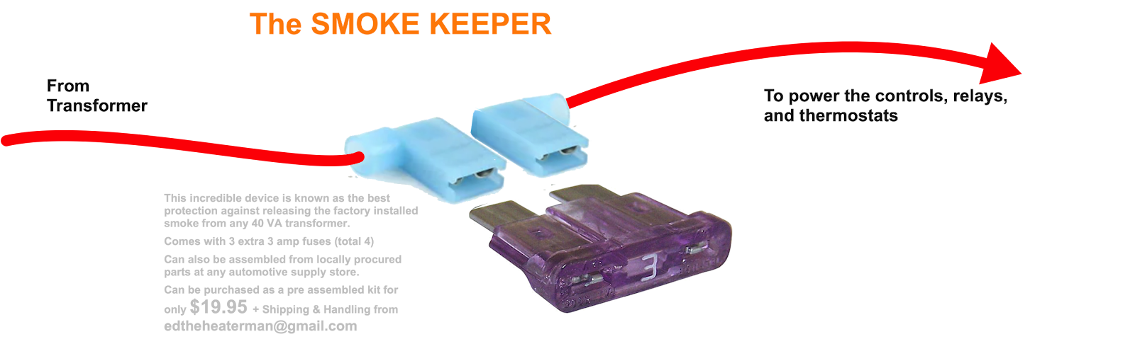
This has been the source of smoke being released from many a transformers across the industry. As a joke I offered this idea as often as I can and one person actually wanted to pay me for the fuse and wires. LOL. I told him it was cheaper at the auto parts store.
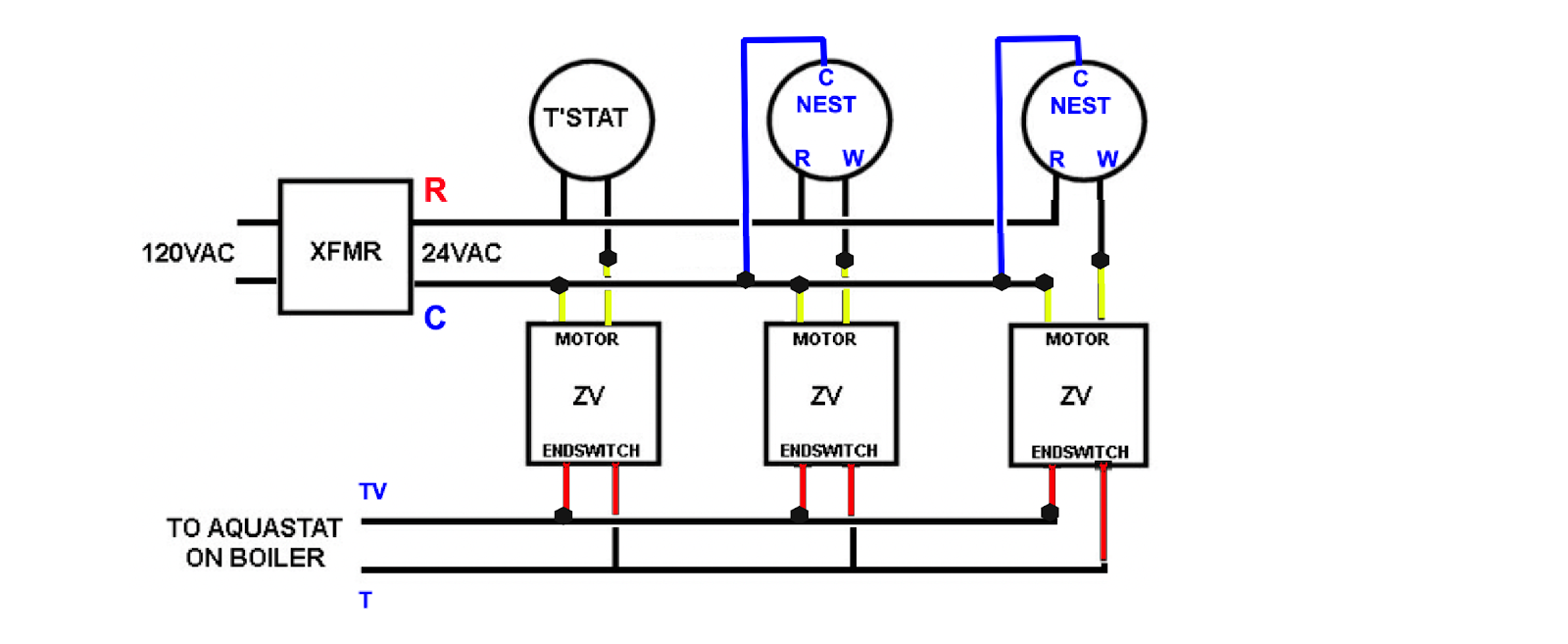
Back to the 3 wire zone valve. This is how it works:
Power from the 24 volt transformer is sent to the thermostat. On a call for heat the power gets forwarded to terminal #1 on the valve head. That is connected to a heating coil that is then connected to terminal #2. Viola a completed circuit.
The heat from the coil will cause wax in a piston to expand and force the valve open. A cam on the valve stem will then close a set of contacts (the end switch) connected to terminal #2 and #3 to complete a circuit. Those contacts can then be used to do what the thermostat on a single zone boiler to do. Make the burner operate and make the circulator operate.
There is the basics that everyone will say they understand in class but when you get to the job with a problem, all that stuff just gets lost.
And here is one of the reasons. There is more than one way to follow the instructions.
All three of these diagrams along with several others, will work by themselves. And as long as you follow the same diagram on all the valves connected to the boiler, you should have no problem. Where the problem happens when is when someone tries to mix and match the different wiring diagrams on the same system. That is when you end up back at the supply house to buy a new transformer. Or even worse, a new expensive control because the transformer in the control lost the fight to the more powerful zone valve transformer.
Here is the diagram on the Taco instruction sheet: Next to it I have added R W and C that I memorized This keeps me on the same page when I troubleshoot zone valve problems. If the valves are not wired this way, I quote the customer a Flat Rate fee to rewire the valves from scratch. If I find a bad transformer or valve that needs to be replaced during my rewire, then I will stop and quote the price for that additional repair. That way I can figure it out during the rewiring and usually solve the problem along the way.
If they are already wired this way, then it is easy for me to find the problem.
Now lets look at what can go wrong when you mix and match the different wiring diagrams. Remember each of the 3 above diagrams will work by them selves.DO NOT USE THIS DIAGRAM FOR YOUR ZONE VALVE SYSTEM Now they are all in the same system. Should be just fine don't you think? But look what happens when you power up that zone valve transformer and the oil burner primary at the same time. The Green Highlighted circuit happens and you let the smoke out of the transformer in the oil burner control because your 40 VA transformer is more powerful than the tiny transformer on that expensive control. DO NOT USE THIS DIAGRAM FOR YOUR ZONE VALVE SYSTEM
When you follow the green lines above, you will basically get this to happen even before you have any calls for heat:
SMOKE
Look at what you just bought for your customer.https://www.supplyhouse.com/Resideo-R8182D1079-Combination-Protector-Relay-Hydronic-Heating-Control-w-High-Limit-10-F-fixed-Low-Limit-Circulator-10F-to-25F?_br_psugg_q=r8182d if it is still available
Wire every zone valve on the system the same way
SO TO SUM UP ZONE VALVE 101
MEMORIZE this:
R on transformer goes to R on thermostat
W on thermostat goes to #1 on the Taco 570 series head
#2 on the Taco 570 Series head goes to C on the transformer
#2 on the Taco 570 Series head goes to all the other #2 on all the other zones
#3 on the Taco 570 series head goes to all the other #3 on the other zones.
All the #2 and all the #3 wires then go to the boiler T T terminals (or wherever the thermostat would go if there was only one zone)
Edward Young Retired
After you make that expensive repair and you still have the same problem, What will you check next?
1 -
Yea. that last one was pretty long, but Taco 570 series valves take lots of mansplaining!
Here is a short one. This is how to take a triple aquastat for Oil Heat and make it work for Gas heat
Not everyone does oil heat BUT having this control on your truck can get you out of a jam three ways.
On the rare chance you have an oil burner call and you need a triple aquastat relay or a cold start relay Then you have what you need
If you come across the rare tankless coil on a gas fired boiler, then you have what you need by adding a 24 VAC transformer to the B1 snd B2 terminals. It also works on millivolt gas valve systems by adding a RIB relaySo you have everything you need without a trip to the supply house to fix
Oil burner on tankless coil boiler for DHW priority
Oil Boiler cold start
Gas boiler with tankless coil for DHW priority 24 VAC gas valve
Gas boiler cold start 24 VAC gas valve
Gas boiler with tankless coil for DHW priority 750 millivolt gas valve
Gas boiler cold start 750 millivolt gas valveThat covers a lot of old boilers out there.
750 millivolt gas valve

24 VAC gas valve

EDIT:
Since this post HydroStat now has a Gas Valve version of this control Hydrolevel 3200. Honeywell does not have the electronic version for gas, so this idea will work on the RESIDEO (Honeywell) L7224U if you need it to.
Edward Young Retired
After you make that expensive repair and you still have the same problem, What will you check next?
2 -
When Vent dampers were introduced in the 1970s It was like open season in the wild west. Everyone wanted to get in on the energy saving bandwagon. Most of those damper manufacturers have gone out of business because they left the safety of the appliance up to the installing individual. Many of the installers were electricians (or wanna bee electricians) that did not understand the safety feature that prevented the burner from operating if the damper was closed. As a result, many consumers experienced serious carbon monoxide problems as a result of improper installation or tampering with the unit when they had a “NO HEAT” call that may or may not have been related to the vent damper. Ultimately the insurance policy for those companies that made the product became too expensive (as a result of too many claims) that there was no longer a profit in it.
Effikal was the winner of the best product but was not a large enough company to stay in business and sold the rights to manufacture that best quality damper to Field Controls. They are pretty much the only vent damper that boiler and furnace manufacturers use today.
Here is the Vent Damper wiring discussion https://forum.heatinghelp.com/discussion/179453/
And my comment about it includes a wiring diagram.
Here is a possible wiring diagram that MAY help you. Post picture of the inside of the L8148E control you have, and the make & model number of YOUR boiler. It looks like a Hydro Therm but I may be wrong
The basic concept (Operational Logic) of an automatic vent damper is to close off a natural draft chimney in order to reduce the down time loss of heat from the boiler and inside the home safely. You don't need Draft Exhaust if there is no flame, because there is no dangerous exhaust when the burner is off.
This must be done Safely by not allowing the burner to operate if the damper is closed. No path for exhaust equals no burner operation.
To accomplish this Safely, the motor mechanism must have 24 V power always. This is to be able to close once the controls and safety devices determine there are no exhaust gases that require venting. The Motor is actually connected to what we call an Actuator. This is the motor and some switches, thermostats, and relays that by design, regulate when the damper may close. In the case of Field Controls and other control manufacturers like United Technologies, and Honeywell, the Molex plug terminal 1 and 4 are the terminals that have constant 24 volts for damper actuator operation. Once it is safe, 24 volts on terminal 1 and 4 will operate the motor until the damper is closed. The internal switches and relays will stop the motor from operating once the damper is in the closed position.
In this closed position the gas valve can not get power to operate the burner as long as the damper is in the closed position.
On a call for heat, IF all the other safety devices are satisfied that it is safe to operate the burner, the #2 terminal on the Molex connector will be energized with 24 volts and the damper motor will start to turn. The motor turns until the damper is in the full open position. Once fully open, the internal relays and switches stop the damper movement and the damper will stay in the full open position. Another set of switches and relays will then energize 24 volts to the #3 terminal on the Molex connector. This then sends power to the gas valve to open and allow the flame to establish. As long as there is a flame or other source of exhaust gasses (or perceived exhaust gasses... by high temperature in the exhaust pipe may be one way to tell) The damper can not close.
Most automatic vent dampers operate on this principle. Some have a spring opening and electric close, but most brands have a damper plate that rotates in the same direction making a 180° revolution every cycle or a 360° revolution every 2 complete burner cycles
Regardless, what ever brand or design of vent damper you have, the safe operation MUST be maintained by proper wiring, and free unobstructed path for the damper plate to open.
All the Professionals on this site fully understand this Sequence of operation (or Operational Logic) for vent dampers. Not all would like to deal with manually wiring of the device and prefer to just "Plug and Play" using a new control on a new damper ... where the now universally accepted "STANDARD DESIGN" makes wiring effortless and fool-proof in most cases.
I hope this helps you with your particular situation. If you feel up the the job, you now have all the information you need. If you are not comfortable with control wiring or do not fully understand the safety and importance of getting this right, then PLEASE GET A PROFESSIONAL that understands how this should work. Where do you find this technician? Go to you local Plumbing and heating or HVAC wholesaler and ask the counter man, "Which one of your customers is good at control wiring?"
They know who they are, because they are the guys that buy lots of controls and never return them because "This darn thing was bad out of the box"Edward Young Retired
After you make that expensive repair and you still have the same problem, What will you check next?
2 -
I love this Guy. Looks like he took a lesson from me on how to make a wiring diagram.

from this discussion https://forum.heatinghelp.com/discussion/195888/
Great detail, and those 3D accents are awesome.
Edward Young Retired
After you make that expensive repair and you still have the same problem, What will you check next?
3 -
I remember reading an article in Fuel Oil News a few decades back that gave specific instructions on how to make a L8124A control on an oil burner with a tankless coil, into a cold start control at low cost to you. That should be done when the plumber disconnects the tankless coil and installs a stand alone electric or gas water heater. Here is the way to do it.
Remove the Blue wire from the B terminal on the LO limit of the control and you will make that L8124A into a cold start boiler control. The required high Limit is still in control of the burner circuit. Back then the control had a stab terminal, so the article mentioned that you need to put a wire nut on the blue wire that you removed. Today's control has an insulated spade connector, so all you need to do is remove it and you are done.
The circulator is still connected thru that LO limit control so you will want to set that LO setting as low as you can get it.
If you want to go a step further, you can just remove the R and the W wires from the LO limit stab terminals and wire nut them together. Then you can leave the blue wire connected. That red and white wire will connect the relay contacts 1K2 directly to the C1 terminal so the LO limit reverse contacts will not keep the circulator from operating. Leaving the blue wire connected to B is just a safe place to keep it since there will be power on it whenever the burner circuit is powered.
Here is the inter wiring from both the L8148A and the L8124A and how they are wired exactly the same for cold start
Edward Young Retired
After you make that expensive repair and you still have the same problem, What will you check next?
2 -
I have made a detailed explanation of Taco zone valves getting connected to NEST and other smart thermostats. This discussion came up in October 2022 regarding honeywell (and other 4 wire ) zone valves. Where do I connect the C wire from a smart thermostat when I have zone valves connected to a L8148 aquastat?
If you have a separate transformer for the zone valves then it is easy.
- R is connected to R on the transformer and all the thermostat R terminals
- C on the valve is one of the yellow wires. It gets connected to the thermostat C and the transformer C
- W on the thermostat is the other yellow wire
- The RED wires are connected parallel to T and TV on the L8148, plane and simple
Then in October 2024 this happened to come in on the same control… But the zone valves use the transformer inside the L8148E 1265. You can only have 2 Honeywell zone valves on that control because all the other stuff already on that control. Here is the diagram and commentary
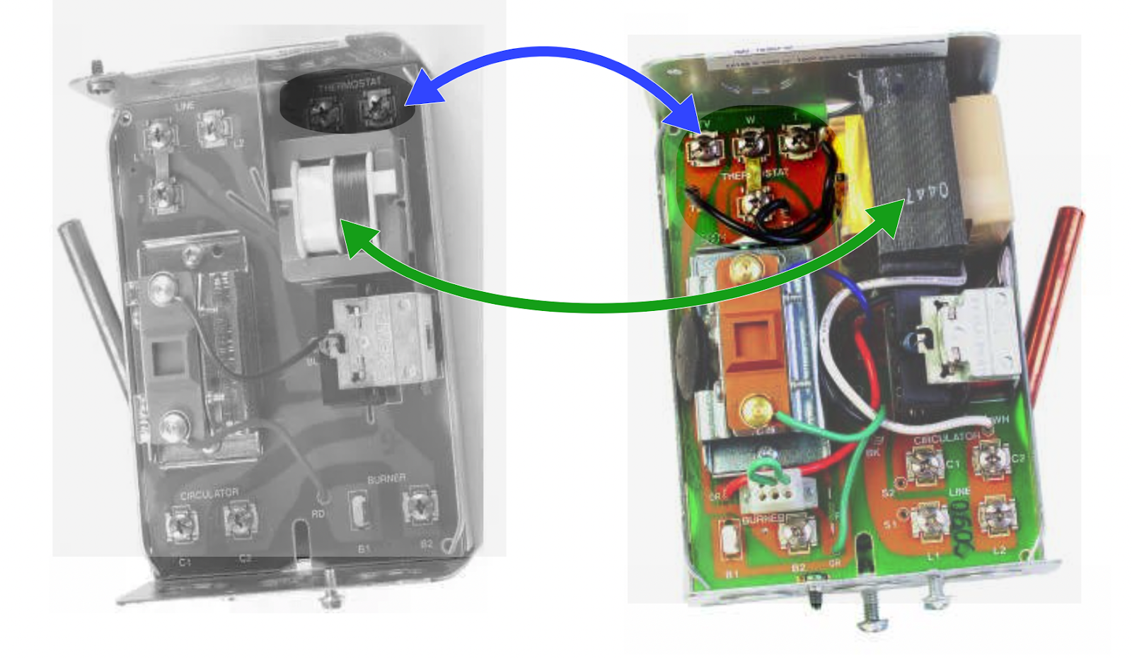
The L8148E has 4 additional numbers after the letter E. This will determine if you have a standard 24 VAC with15 to 20 VA rating or if you have the 24VAC with a 40 VA rating. Also a photo of the inside wiring will also indicate if you have a 40 VA transformer. If you have the larger capacity transformer, it can handle 2 zone valves, and you do not need a dedicated transformer for the zone valves.
These two photos show the difference between the L8148 with a standard transformer and two thermostat terminals marked
T T(black and white photo) and the L8148 with the larger transformer with four low voltage terminals markedT, TV, WandZ. (color photo). See the difference in the size of the transformer? (Green arrow). If you have the control on the right, then you may not need a separate transformer for the zone valves.In order to find the C terminal for your Smart Thermostat, you may need to change the wiring on the thermostat and zone valves. With a 2 wire thermostat (labeled
RandW) it does not matter if you place theRonTorTVon your control in which case theWfrom the thermostat will be placed on aYellow of the zone valves. When using a Smart thermostat it is important to put theRfrom the thermostat on theTVof the L8184 ONLY and theWfrom the thermostat one of theYellow wires of the zone valve, that will make sure that you can use theWon the L8184 as theCfor the thermostat and the zone valve otherYellow wire.It is important to wire both zones identical or you may connect a dead short by accident. I recommend this device to be placed on the
TVterminal of the L8148 control then connect all theTVwires to the other end of the fuse.I do not actually sell these, it was presented as part of another post as a device that does not let the
factory installed smokeout of the control transformerAssuming you have the L8148E 1265 or similar control, here is the diagram for using the internal transformer of the L8148E 1265 to operate 2 zone valves and 2 smart thermostats. That is the maximum load you can place on this transformer. That is because this control transformer is powering 2 zone valves, one vent damper motor, one ignition control, one gas valve, one (burner and circulator)
K1relay coil, and now two smart thermostats.TVon the L8148 is connected to theRof both thermostats and also gets connected to one of theRed wires of each of the zone valves.Ton the L8148 is connected to the otherRed wire of both zone valvesWon the L8148 gets connected aCommon to both zone valve motors and both thermostat by connecting it toCon both thermostats and the otherYellow wire of both zone valves. Leave the factory installed jumper on the L8148 connected toZEdward Young Retired
After you make that expensive repair and you still have the same problem, What will you check next?
1 -
On Tuesday Nov. 26 2024 @epmiller wrote this about a post where a homeowner replaced a Taco SR501 after checking how it operated from the thermostat location. The OP determined that SR501 was the problem and replaced it, only to find that the new SR501 had the same defect. Or was the SR501 defective at all?
Here is what @epmiller was referring to:

Checking the basement control (in this case the SR501) from location A will eliminate the thermostat ONLY from being the problem. Disconnecting the wires at location B will eliminate the thermostat AND any wiring problems between the thermostat and all the wires in the walls to the control, by using a jumper at the control.
Edward Young Retired
After you make that expensive repair and you still have the same problem, What will you check next?
1 -
This was my first post.
Here is an AI video of that post
Hay @MikeAmann, and @pecmsg Let me know what you think of this AI generated video
Edward Young Retired
After you make that expensive repair and you still have the same problem, What will you check next?
2 -
This post from January 2024 has the typical Steam Boiler wiring diagram that uses the "Fan Center" type transformer with a relay socket that is not used, since a steam boiler does not need the relay to operate a circulator (or fan for that matter). The following diagram is the same thing when use on a water boiler that does use the relay to operate the circulator. this one has the vent damper circuit, but it is not the important part of the diagram. the C wire is the important part of the diagram

You can see that the Burnham and the WM are very similar diagrams. The important part of the diagram when you need the C wire is that the R on the transformer is connected to the R on the thermostat that requires the C wire. When the thermostat only had two wires, the labels on the black wires from the R and the G terminals were marked T T because it didn't matter wether the R on the thermostat went to G or R on the transformer. When you introduce the C wire, YOU MUST MAKE SURE the R on the thermostat is connected to the R on the transformer. After that it is easy top get therest of the wires connected.
Edward Young Retired
After you make that expensive repair and you still have the same problem, What will you check next?
0 -
Add isolation relay to a WM steam boiler with LWCO and Vent Damper
The copy and past feature is a little different with the new updated website here. This is how to use a fan center combination transformer/relay to isolate the NEST or other smart thermostats the require a C wire. I will copy and paste the diagrams from the URL links below the post.


Edward Young Retired
After you make that expensive repair and you still have the same problem, What will you check next?
0 -
Here is one that I really liked working on. Someone wanted to connect a TAM7 air handler (American Standard/TRANE with Variable speed fan) with the AS Hydro Coil kit for heat, to a Navien ModCom combi boiler
First diagram I did some crazy relays to operate the two circulator pumps and came up with this in order to prevent the fan from blowing cold air when the boiler stopped the CH circulators for priority on the DHW. this shows only one for the two Taco SR501 relays and the R4222 general purpose relay to stop the two pumps from operating, is also missing

The I looked closer at the Navien NCB wiring and found that the boiler control could handle up to 3 circulator zones. I was able to accomplish the same thing without the Taco Switching relays and made this diagram.

Now the circulators for both air handler zones will stop for DHW priority while the AH terminals stop the fan on each air handler using the general purpose relay (Like an R8222A) And The OP liked the drawing but followed up with the fact that the first floor air handler was 2 zones by way of a duct damper zone control. So there are 2 zones on one air handler and one zone on a second air handler. All connected to a ModCon boiler that has ODR and DHW with a priority. And you don't want to blow cold air thru the duct work on a call for heat while your teenaged daughter takes a 20 minute shower. (yea I know 20 minutes is short for a teenager)
So I came up with this one:

Now connect the thermostats to the zone control for the first floor duct zones. The zone damper will connect to the TAM7 air handler that is turn will connect to the boiler control with the Hydro Coil accessory, using the boiler zone feature to connect the circulators for zone 1 and zone 2. On the second floor connect the thermostat directly to the TAM7 as shown in the diagram in the middle of this post. then follow the same diagram to connect to the boiler zone 2 with the Hydro Coil accessory.
Now if someone does this for their customer and does not make this diagram so that it can be posted with the equipment somewhere, then they are no completing the job properly. How is the next guy supposed to figure this out?
I hope this helps someone with a variable speed air handler that wants to connect to a hydronic heat duct coil using only one thermostat that will figure out everything by just setting the heat/cool switch and setting the desired temperature. That is all the customer wants to do. They don't want to become an electrical engineer in order to switch over from winter operation to summer operation.
Edward Young Retired
After you make that expensive repair and you still have the same problem, What will you check next?
1 -
Just when I thought everything was just perfect, This message threw me for a loop"
“Should have also mentioned, I have this Taco zone controller in between the handlers and the boiler. This is the only device that instructs the boiler to run (currently "Isolated End Switch" on the ZVC404 is wired to the TS_ZONE3 on the Navien
But the OP was mistaken and actually ment to say that this was the control that was between the air handler and the boiler.

This made more sense and so I updated the diagram with one addition. The OP did not want to stop the air handler operation for just a short DHW use, like washing your hands, so I added a time delay from the Navien AH switch to the R8222 relay in order to delay opening the thermostat contacts from the thermostat to the TAM7 air handler. HERE IS THE DIAGRAM

Edward Young Retired
After you make that expensive repair and you still have the same problem, What will you check next?
2 -
What an over-achiever you are Ed! Thanks for all the time you spend on these schematics.
Bob "hot rod" Rohr
trainer for Caleffi NA
Living the hydronic dream 5
5 -
Still not done…. The OP got the time delay and installed it according to my design only to find a flaw. It has to do with the way that the A/H contacts on the Navien operate. They are open when there is no call for heat and close on a call for heat. That presented a problem because there can not be a call for heat unless the A/H contacts are closed.
"Catch 22".
Can't get a call for heat without A/H closed, Can't Close A/H until a call for heat
So I spent some time with Tech Support and had a nice chat with Bill. Explained the Catch 22 and asked him about the set of contacts called "DHW PRI". Turns out he thought that would not help…. BUT IT DOES. By using the DHW PRI contacts that stay open all the time and close on a demand for DHW, I just connected that relay the same way, with the DHW PRI contacts that close to activate the relay and used the NC contacts on the relay to open when that happens. I think this will finally get the OP to a place that works

Here is the close up of the change. (Red Arrow)

Edward Young Retired
After you make that expensive repair and you still have the same problem, What will you check next?
1 -
Here is something that may be needed in order to get your TAM7 variable speed air handler to stop blowing cold air. Your thermostat must be programed to use the green wire to turn on the blower for heat. (I need to check the TAM7 info to see if that is possible) Then a Heat Relay, a Heating Fan Relay and a L6006C Aquastat must be added in order to send the circulator Taco SR502 a signal and the boiler's burner the signal to operate… Along with a second relay to open the G (fan) wire circuit from the thermostat and then compete the G wire thru the L6006C (the shaded area)
This diagram was to solve thesame problem of bowing cold air on a variable speed air handler

This will solve your problem completely without using the Navien A/H or the DHW PRI terminals, as they seem to have some issues when more than one air handler is used.
Edward Young Retired
After you make that expensive repair and you still have the same problem, What will you check next?
1 -
Seems that I have been able to solve some issues with Power Vent controls for several wallies. I wanted to put a couple of those diagrams here so I can find them easier in the future
The link in the following post is for an oil fired furnace with a R8184G or similar 3 wire primary.
The next one is the same furnace with an electronic primary control, like the Honeywell/Resideo R7248U or the Beckett Genesis, or the Carlin 70200.

Some of the Oil Fired furnaces on the market today have a fan timer control like the Honeywell/Resideo ST9103. This control has a 9 pin Molex connector that uses the orange wire from the primary control for the Circuit board software. The orange wire from the primary control does not get connected directly to the oil burner motor. The orange wire gets connected to the 9 pin plug in order to let the ST9103 know that the burner motor is powered thru pin #1. Then pin #2 is connected to the motor. When you come across this setup you do the same thing as you would on the furnaces without that ST9103. Connect the orange wire from the primary control to power T1 on the CK63. Then you connect T3 from the CK63 to the pin #1 on the 9 pin Molex as shown here.

Edward Young Retired
After you make that expensive repair and you still have the same problem, What will you check next?
2 -
Hi @EdTheHeaterMan , I'm thinking you have the bones of a book here… a very useful book! Throw in some of your humor and you'll have a bestseller! All that's needed is a title… or maybe that's already done.🤔
Yours, Larry
4 -
Nice… See that @EdTheHeaterMan , another has suggested that you publish. Really. No BS. I think it would be a great guide and a good read for many.
0 -
This!
Baltimore, MD, USA
Steam, Vapor & Hot-Water Heating Specialists
Oil & Gas Burner Service
Consulting0


Categories
- All Categories
- 87.7K THE MAIN WALL
- 3.3K A-C, Heat Pumps & Refrigeration
- 59 Biomass
- 430 Carbon Monoxide Awareness
- 129 Chimneys & Flues
- 2.2K Domestic Hot Water
- 5.9K Gas Heating
- 122 Geothermal
- 170 Indoor-Air Quality
- 3.8K Oil Heating
- 79 Pipe Deterioration
- 1.1K Plumbing
- 6.6K Radiant Heating
- 396 Solar
- 16K Strictly Steam
- 3.5K Thermostats and Controls
- 56 Water Quality
- 51 Industry Classes
- 51 Job Opportunities
- 17 Recall Announcements