Summer project: DIY Zone Synchronizer + De-Thunker

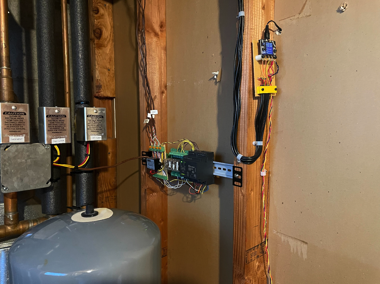
In an attempt to at least slightly improve on these issues, I trimmed and labeled all of the wires, and built a microcontroller-based 'interposer' that sits between the 3 thermostats and the boiler.
- The thermostats are now all wired to 24VAC relays with integrated status LEDs
- The relays each switch a 12VDC signal to the microcontroller, so that it knows which zones are calling for heat
- The microcontroller directly controls each of the three zone valves, as well as a relay wired in series with the TT switch to the boiler. The boiler itself continues to control the circulator and regulate the supply water temperature whenever TT is closed.
The microcontroller can operate in either a 'pass-through' mode where the tstat signals just get directly passed to the zone valves, and the TT_Enable switch is always asserted, or 'fancy' mode, where I can add and test out new features. Currently it does:
- Zone synchronization. Wait for all 3 zones to call for heat, then enable each until the thermostat is satisfied for this cycle.
- "De-thunking" - when a thermostat is satisfied while multiple zone valves are open, disable the TT signal to the boiler to temporarily shut off the circulator. Allow zone valve to close, then re-enable the TT signal and allow the circulator to resume. Ideally this wouldn't occur while the boiler is firing, but for now the microcontroller isn't aware of the firing state.
Comments
-
What circulator are you using? A delta p type nay eliminate the sone valve noise, save power and prevent over- pumping when only one or two zones flow
if you have a fixed speed circulatorBob "hot rod" Rohr
trainer for Caleffi NA
Living the hydronic dream0 -
It's a Taco 007-F5 connected so that it's on the return side of the boiler (while the expansion tank is on the supply side of the boiler, so it's pumping through the boiler and towards the expansion tank). Reducing energy usage of the circulator would be nice, for both overall power savings, and because I wired the boiler with a transfer switch so that it could be run from a 2 KWh backup battery, so lower usage == longer run time without me needing to recharge the battery.0
-
Any issues with air removal or air noise? Changing the expansion tank or circ would sort that out
EcM pumps that size run around 37w, the 007 probably over 75w? Plus the system behaves better, flow wise.Bob "hot rod" Rohr
trainer for Caleffi NA
Living the hydronic dream0 -
I think at the beginning of the season I usually notice 'gurgling'/running water noises coming from the general area of the boiler for a while, but it's never been significant enough for me to bother characterizing it well. The boiler has an automatic air vent coming off of it that I see some signs of mineral deposits on, so presumably something is getting vented from that occasionally. Most of the noise I associate with the heating system is just the 'plinking' noise of thermal expansion and the fins sliding along the plastic guide things (and the 'thunking' noise when a zone valve closes sometimes).
I think running the boiler from the battery seems to draw about 85W, so that lines up well with your estimate (and it would double the runtime if I dropped 40W!). Would swapping in a delta-P circulator without relocating it or the expansion tank perform poorly?0 -
I have one comment, for the benefit of the next person or the next tech.
DOCUMENT EVERYTHING. Wiring diagrams (all wires labelled). Component descriptions, part numbers, equivalents. All possible operating modes. Write it all down and put it somewhere where it can be found.Br. Jamie, osb
Building superintendent/caretaker, 7200 sq. ft. historic house museum with dependencies in New England 2
2 -
@Jamie Hall - excellent point. I need to finish labeling everything and doing a circuit diagram for it. It's intentionally designed to take about 5 minutes to return the wiring to 'normal' (and bypass all of the microcontroller stuff), although I was strongly considerin adding a physical bypass switch to it as well. The microcontroller also boots directly into 'pass-through' mode and has a built-in watchdog timer to reboot it if it hung for some reason.0
-
A pic of the boiler piping would show if you have an air purger or just an air vent.
Are you thinking of waiting until all 2 zones call before running the boiler?
Does the boiler have an outdoor reset control? that can help lessen short cycling, by lowering supply temperature on milder days. Saves some fuel consumption.
This issue explains how the variable speed ECM circulators work with zone valved systems.
There were some rebate programs available for upgrading to ECM pumps, check here.
www.dsireusa.org click on your state.
https://www.caleffi.com/sites/default/files/coll_attach_file/idronics_16_na_0.pdfBob "hot rod" Rohr
trainer for Caleffi NA
Living the hydronic dream0 -
If it’s that grossly oversized, get a properly size boiler!0
-
@pecmsg - as much as the inefficiency bothers me, when the heat loss of my house is so low, any savings from operating cost would be swamped by the installation costs. My boiler only used 325 therms this last season, with an estimated ~50% efficiency. If I could magically install a perfectly matched modcon, it might knock that down to 180 therms or something and save $300-$400/year in the best case. For the kind of money to install a new boiler, I'd rather put in mini-splits and get A/C too.1
-
@hot_rod

- Current control algorithm is just to wait until all 3 zones are calling for heat before closing the TT signal to the boiler. It has a real-time clock, so I could add a 'timeout' that could even operate on a per-zone basis. I'm fine tolerating wider temperature swings in the basement, for instance.
- There's no current outdoor reset control, but I have the SWT set to bounce between 150F-130F, which is pretty much as low as a noncondensing boiler should go. That lengthens the heating cycles, but I think it shortens the burn cycles (at least the initial one when the water is at room temp).
- I wasn't worried about the zone valves, I was curious if the pressure-sensing nature of the circulator would somehow be more poorly behaved if the circulator is pumping into the expansion tank.
0 - Current control algorithm is just to wait until all 3 zones are calling for heat before closing the TT signal to the boiler. It has a real-time clock, so I could add a 'timeout' that could even operate on a per-zone basis. I'm fine tolerating wider temperature swings in the basement, for instance.
-
Not the best of air removal strategies, better than nothing.
These rehab projects always come down to how much time $ to spend for small improvements in performance.
If there were an extra tee near that low water cutoff, the exp tank connection could be moved there, pump stays as is. Now you are pumping away. Fill valve connection would move along with the tank.
Again is it worth the trouble if the system works quietly?
The ECM upgrade would work regardless of the tank location. Air removal is the biggest plus of pumping away.
Looks like a generator plug? I assume it is not hot until you flip the switch?Bob "hot rod" Rohr
trainer for Caleffi NA
Living the hydronic dream0 -
Correct re: generator plug - it's a 3-position switch that's off, connected to house hot+neutral or connected to generator hot+neutral. The exposed plug is never connected to the house hot or neutral.
The LWCO is still connected 'upstream' of the circulator, so how would moving the expansion tank there help?
Speaking of LWCO, while I have your attention, what's up with how rusty it's gotten?
0 -
It takes 15 minutes for a boiler to stabilize.fentonc said:@pecmsg - as much as the inefficiency bothers me, when the heat loss of my house is so low, any savings from operating cost would be swamped by the installation costs. My boiler only used 325 therms this last season, with an estimated ~50% efficiency. If I could magically install a perfectly matched modcon, it might knock that down to 180 therms or something and save $300-$400/year in the best case. For the kind of money to install a new boiler, I'd rather put in mini-splits and get A/C too.You’ll get a payback.You can’t fix bad design with controls0 -
@pecmsg - I'm not expecting any miracles out of my control scheme, but it would be fun if it was a measurable improvement. Re: payback - for what I paid to have the boiler installed ~7 years ago, the payback period would be on par with the lifetime of the boiler. High labor costs in this part of the country make minor efficiency improvements a hard sell, although maybe it will finally motivate me to get some basic plumbing skills at some point
") 0
0 -
Have fun!fentonc said:@pecmsg - I'm not expecting any miracles out of my control scheme, but it would be fun if it was a measurable improvement. Re: payback - for what I paid to have the boiler installed ~7 years ago, the payback period would be on par with the lifetime of the boiler. High labor costs in this part of the country make minor efficiency improvements a hard sell, although maybe it will finally motivate me to get some basic plumbing skills at some point
0 -
Hello @fentonc,
I would think this strategy may make the zone with the highest heat loss have a very wide temperature swing. Since it is waiting for the zone with the least heat loss to cool enough to fire the boiler. If the highest heat loss zone is the basement it may not be an issue for you.fentonc said:- Zone synchronization. Wait for all 3 zones to call for heat, then enable each until the thermostat is satisfied for this cycle.
- "De-thunking" - when a thermostat is satisfied while multiple zone valves are open, disable the TT signal to the boiler to temporarily shut off the circulator. Allow zone valve to close, then re-enable the TT signal and allow the circulator to resume. Ideally this wouldn't occur while the boiler is firing, but for now the microcontroller isn't aware of the firing state.
I would consider a strategy like this;
Only the highest heat loss zone controls the boiler and circulator, since this zone should be calling more often than any other. This could be overridden by your no freeze strategy as needed.
The lower demand zones can call when ever they want but unless the highest heat loss zone is active they will not fire the boiler.
When highest heat loss zone call ends they all do, no thunking.
As far as a no freeze strategy you may want to just have an additional control means to power the circulator and the problem zone valve without firing the boiler. Which may be just adding one more relay as a parallel control path to energize the circulator as needed.
I think I would have an easy means to normalize or disable the additional control so if a HVAC contractor is needed their head does not explode.
National - U.S. Gas Boiler 45+ Years Old
Steam 300 SQ. FT. - EDR 347
One Pipe System0 - Zone synchronization. Wait for all 3 zones to call for heat, then enable each until the thermostat is satisfied for this cycle.
-
I thought maybe the LWC was teed into the pipe above the circ, guess not.fentonc said:Correct re: generator plug - it's a 3-position switch that's off, connected to house hot+neutral or connected to generator hot+neutral. The exposed plug is never connected to the house hot or neutral.
The LWCO is still connected 'upstream' of the circulator, so how would moving the expansion tank there help?
Speaking of LWCO, while I have your attention, what's up with how rusty it's gotten?
The rust is from the relief and maybe the LWC having a leak at some point. Sometimes the rust seals a small seep type leak if it has stopped?
If you enjoy tinkering, have at it. I think @109A_5 logic may be a bit more appropriate. Either is a work around, of course.
Bob "hot rod" Rohr
trainer for Caleffi NA
Living the hydronic dream0 -
Hello @fentonc,
As I'm sure you are well aware with microcontroller-based, PLR, PLC based control you can easily experiment with different strategies, maybe even have a mode switch to easily change configuration modes manually or by some other stimulus.
Also the zones with less heat loss could have an call delay that starts when the zone with highest heat loss calls for heat, thus justifying the zones with less heat loss to heat more towards the end of the zone with the highest heat losses call, may help minimize any temperature overshoot.
National - U.S. Gas Boiler 45+ Years Old
Steam 300 SQ. FT. - EDR 347
One Pipe System0 -
Hello @fentonc,
Building on my last post, and possibly depending which programming language you chose to use with that PLC, you could make the call delay dynamic for the slave zones with some non-blocking code. This would give you almost the exact same thermostat control you had before with the features you wanted to add.
National - U.S. Gas Boiler 45+ Years Old
Steam 300 SQ. FT. - EDR 347
One Pipe System0 -
@109A_5 - Easily making it 'normal' is a big concern of mine, so it boots into what I call "P=oass-through" mode if it gets power-cycled or reset by the watchdog timer, in which case it should be indistinguishable from its original scheme (tstats wired to zone valves, end switches wired in parallel to boiler TT signal). A button on the controller toggles between that and the custom mode, although I'm thinking about adding an actual physical bypass toggle switch.
The code for it is written in C++, so it's pretty trivial to implement any scheme you can come up with. For the three zones, the heat loss for the first floor is highest (lots of windows, which also complicates things as it gets quite a bit of solar gain on sunny days). In terms of the radiation:heat loss ratio, the basement and 2nd floor are pretty closely matched and have about 50% more radiation relative to heat loss than the 1st floor.
Is the motivation for closing them all at the same time just to avoid the stop-close-restart 'dethunking' scheme I proposed (which has at least some risk of interrupting burn cycles)?
For the schemes with initial delays on the other two zones, it seems like it would lead to substantially shorter burn cycles on the initial (and longest) burn because only a single zone would be opened. It probably wouldn't be that difficult to implement the dynamic call delay scheme (with a control loop that changes the delay from cycle to cycle based on if the thermostat was satisified or not at the end of the previous cycle). I'll definitely consider just letting the 1st floor (with the highest heat loss) drive the cycle.
I have pretty good monitoring of both room temperatures and various boiler metrics, so hopefully I can try things out and get some feedback pretty quickly.0 -
Hello @fentonc,
I understand power up defaults and watchdog timers and best intent to make it bulletproof. However it is still electronics and it can fail at the worst possible time. For me if it is 1:00AM and the house is getting cold because it is 10 Degrees Fahrenheit outside, I want a quick easy fool proof way to totally bypass the PLC control. I would utilize the NC contacts (the resting state) of the relays and a few DPDT switches. It should not be too hard to do with careful wiring planning. And then there is the benefit of the ability to normalize the system for a contractor or yourself if needed. PLC goes nuts or is inoperative, flip maybe 3 or 4 switches and power down the PLC, done, normalized until further troubleshooting can be done.fentonc said:@109A_5 - Easily making it 'normal' is a big concern of mine, so it boots into what I call "P=oass-through" mode if it gets power-cycled or reset by the watchdog timer, in which case it should be indistinguishable from its original scheme (tstats wired to zone valves, end switches wired in parallel to boiler TT signal). A button on the controller toggles between that and the custom mode, although I'm thinking about adding an actual physical bypass toggle switch.
OK, I fairly familiar with 'Arduino C++' (as I like to call it) although I have not done any projects with the Opta. So I think you are in a good place as far as programming flexibility as long as you have enough I/O ports. The software could also actually dynamically pick the zone with the highest heat loss (or longest run time), since I suppose it could change throughout the day with changing weather conditions. I just wanted to keep the concepts simple at first.fentonc said:The code for it is written in C++, so it's pretty trivial to implement any scheme you can come up with. For the three zones, the heat loss for the first floor is highest (lots of windows, which also complicates things as it gets quite a bit of solar gain on sunny days). In terms of the radiation:heat loss ratio, the basement and 2nd floor are pretty closely matched and have about 50% more radiation relative to heat loss than the 1st floor.
Yes, your 'thunking' issue (if I understand it correctly) is if a zone valve closes during a cycle that is extended or lengthened by another zone, like a water hammer. I really don't like the idea having to shut down the TT call to just close a zone valve if another zone is still calling. Less wear and tear.fentonc said:Is the motivation for closing them all at the same time just to avoid the stop-close-restart 'dethunking' scheme I proposed (which has at least some risk of interrupting burn cycles)?
Also you wanted to synchronize the zone calls to reduce the wear and tear of the boiler equipment and maybe have better system efficiently too, correct ?
So if you remove the boiler TT call (circulator stops) then close any open (or all) the zone valves, no water hammer, right? The zone sync alignment is at the end of the cycle instead of the beginning. Also I did not like the strategy to wait for all the zones to call before firing the boiler. What if one zone only calls once a day? I think this method may or has the ability to produce very uneven heat.
Sure this method that I have described is certainly more code and time to test and verify. I think it would be worth it with the goals you set.
I assume you are doing something like this, a very simple block diagram. The auxiliary circulator control is for the zone freezing issue.
National - U.S. Gas Boiler 45+ Years Old
Steam 300 SQ. FT. - EDR 347
One Pipe System0 -
Hello @fentonc,
Well I looked at some of the specifications on the Opta. I'm kind of disappointed, only 4 outputs and they are all only Normally Open contacts. And no Expansion modules available yet.
Anyway I would try this, move your output that is presently in series with the TT wires to the Boiler's Auxiliary Limit connection point. This way a TT call will always turn on the circulator and you can independently control the actual firing of the boiler. So whatever anti-freeze strategy you choose you may not have to fire the boiler to just move warm water through the zone with the freezing issue. If the outdoor temperature is above a value of your choosing the anti-freeze strategy could be automatically disabled.
The added relay uses its Normally Closed contacts so not a problem if the PLC is disabled or bypassed. Only disables the fire when needed.
Edit: When I wrote this post I totally forgot you were using an Opta output to control the circulator for "De-thunking" purposes. So maybe @hot_rod's suggestion below would help. Or maybe with all three calls to the zone valves terminating at once (if three were active), for example, like I described before, with the active end switches all opening at almost the same time, shutting down the circulator before the valves have a chance to fully close would also help. You would have to experiment. The number of Opta outputs kind of limits your options and independent functionality.

National - U.S. Gas Boiler 45+ Years Old
Steam 300 SQ. FT. - EDR 347
One Pipe System0 -
The zone valve hammer is a very fixable problem. Some troubleshooters claim un-hooking one of the two springs inside will eliminate the hammer. Basically slowing down the close motion, which initiates the hammer most often. Certainly a simple thing to try. Or the ECM pressure regulated circulator.
Then you could focus on the short cycles with the computer "fix", instead of trying to get two fixes from the PLC.Bob "hot rod" Rohr
trainer for Caleffi NA
Living the hydronic dream0 -
Hello @fentonc,
For projects like this, the beauty of software, if you can dream it and code it, you got it, if you don't like it change it. The hardware is probably already out there, you buy or build it.
With the software monitoring the thermostat activity, the code only allowing the heating of the home during a certain window (zone synchronization), all zones terminate at the same time "De-thunking", dynamic delays to compensate for various heating loads, and burner control for no-fire warm water circulation antifreeze protection, it may work very well.
With the call for heat window, the call starting the window could be any zone, some zones would have a delay. If another calls it may have to wait for the balance of its delay to expire. When any zone is satisfied they all drop out "De-thunking". If one zone was effectively cut short, there is a global delay before the next window can start. Cycles per hour, if you want to think of it that way. This may help even out the overall heating of the home.
Also I don't recall it mentioned before (maybe I missed it), could he master bedroom be easily converted to its own zone ? Sadly the Opta has limited outputs.
Even though the Opta is a nice 'Off the Shelf' PLC type product with the infinite versatility of Arduino C++ the outputs are presently limited. Maybe by the time you add a zone for the master bedroom (if ever) an output expansion module will be available.
Another option in this situation, if I wanted to code with Arduino C++, I may have just built my own PLC type device using an UNO or a Mega, much more I/O.
National - U.S. Gas Boiler 45+ Years Old
Steam 300 SQ. FT. - EDR 347
One Pipe System0 -
@109A_5 - Yeah, the output limitations on the Opta are obnoxious, but 1) I didn't want to have to spin a board or use a flaky stack of shields if I could avoid it, and 2) sometimes limitations help protect you from yourself in terms of getting too ambitious. The design I came up with (3 zone valves and the relay to gate the TT signal) only required 4 relays, so I figured I'd give it a shot. You've convinced me to add a physical bypass switch to make the wiring 'normal' rather than rely on the microcontroller running in pass-through mode.
I'm coming around to the idea of the scheme you're proposing - no waiting for the 1st floor tstat (which has both the highest heat loss, and is the one we're most likely to adjust the thermostat on), and no risk of cutting burn cycles short whenever the other two zones shut off. It has more risk overshooting (rather than risk of undershooting with the other scheme), and it shortens the initial burn when the first zone calls for heat. It's easy enough to implement that I'll probably try out both and see if one obviously works better.
@hot_rod - Do you have a specific recommendation for a replacement circulator? The current one is a Taco 007-F5. I see Taco has the 007e series, but I don't know if that's appropriate.
Thank you for all of your suggestions - this is exactly the sort of feedback I was hoping to get.0 -
Every pump brand has ECM circulators now that have similar functions, pick a color😉
Ive been using Grundfos Alphas since they came out years ago. Not a single failure!
The latest offering has a basic model and this one with more features.https://www.supplyhouse.com/Grundfos-92603108-ALPHA-15-58FR-Circulator-Pump-w-Rotated-Flange-Mount-115V-1-20-HP-GF-15-26?srsltid=ASuE1wTepvnMfx4qAIx4GNNxeHKyuGVBQq0hJpVgPN1TXudDAvqxqGQvgSs
This rotated flange version should be a direct replacement for the pump you have.Bob "hot rod" Rohr
trainer for Caleffi NA
Living the hydronic dream0 -
Hello @fentonc,
Maybe something like this for the hardwired bypass. A single 3PDT or 3 separate SPDT switches could be used. I like the software bypass, I just think it should have a hardware bypass too.
National - U.S. Gas Boiler 45+ Years Old
Steam 300 SQ. FT. - EDR 347
One Pipe System0 -
Thanks to everyone's advice I added a 4PDT toggle switch that completely bypasses the PLC, and I still have a solid 2" or so of space on my DIN rail! It's still wired with the 3 zone valve controls as well as the "TT_Enable" output, although using that for de-thunking vs shifting the heating calls to all end simultaneously will just be software options.

Next up is to post a proper schematic above it.
 1
1 -
Hello @fentonc,
IMO, if you justify the 'zone sync' to the end of the call(s), the "TT_Enable" output functionality is no longer needed and should be repurposed (NC contact of a buffer relay) to disable the burner only, as illustrated in an above post since any software only call to any zone will enable the circulator for the anti-freeze functionality.
Disable burner (open NC relay contact).
Call the freeze prone zone for maybe 40 to 90 seconds (zone valve time + amount of flow time needed).
Release zone call.
Delay for zone valve end switch to open.
Enable burner (close NC relay contact).
With non-blocking code if another zone call becomes active during the anti-freeze functionality the burner could be enabled as needed and the new call processed as normal and the anti-freeze functionality timing would terminate as it normally would. No waiting, delay or interruption of any process.
I would not bother to fire the boiler for the anti-freeze functionality, only enable the circulator, I would think the boiler water would be warm enough for that anti-freeze purpose.
One step at a time, so far looking good.
National - U.S. Gas Boiler 45+ Years Old
Steam 300 SQ. FT. - EDR 347
One Pipe System0 -
It is tempting - I would need to figure out how to wire in an additional limit switch, but I already have a spare buffer relay in that block of relays for the thermstats. It would also allow me to run with a higher differential than the fixed 20F one the boiler controller comes with, or add some kind of fancier 'heat purge' scheme at the end of a cycle (I would probably want to add a temp sensor on one of the water pipes that feeds back to the Opta, but I have plenty of spare inputs).0
-
Hello @fentonc,
See the boiler wiring diagram in the post above a bit, utilizing the boiler's 'Additional Limits' connections to a Normally Closed relay contact should be fairly easy, probably easier than all you have done so far, just add the wire(s) when you are ready.
National - U.S. Gas Boiler 45+ Years Old
Steam 300 SQ. FT. - EDR 347
One Pipe System0 -
Hello @fentonc,
If you can dream it, build it and code it, you got it. If you like to build and find you need more relay outputs, using some older tech you could easily add up to 15 relays. The relay control can be aliased and manipulated in software. There are some off the shelf relay boards too.
An inexpensive example with 5 total output relays (3 with NC contacts too, not drawn);
Or if you use 3 Opta outputs you can control 7 relays for a total of 8 relays.
National - U.S. Gas Boiler 45+ Years Old
Steam 300 SQ. FT. - EDR 347
One Pipe System0


Categories
- All Categories
- 87.7K THE MAIN WALL
- 3.3K A-C, Heat Pumps & Refrigeration
- 59 Biomass
- 430 Carbon Monoxide Awareness
- 129 Chimneys & Flues
- 2.2K Domestic Hot Water
- 5.9K Gas Heating
- 122 Geothermal
- 170 Indoor-Air Quality
- 3.8K Oil Heating
- 79 Pipe Deterioration
- 1.1K Plumbing
- 6.6K Radiant Heating
- 396 Solar
- 16K Strictly Steam
- 3.5K Thermostats and Controls
- 56 Water Quality
- 51 Industry Classes
- 51 Job Opportunities
- 17 Recall Announcements