Understanding the Taco 007e

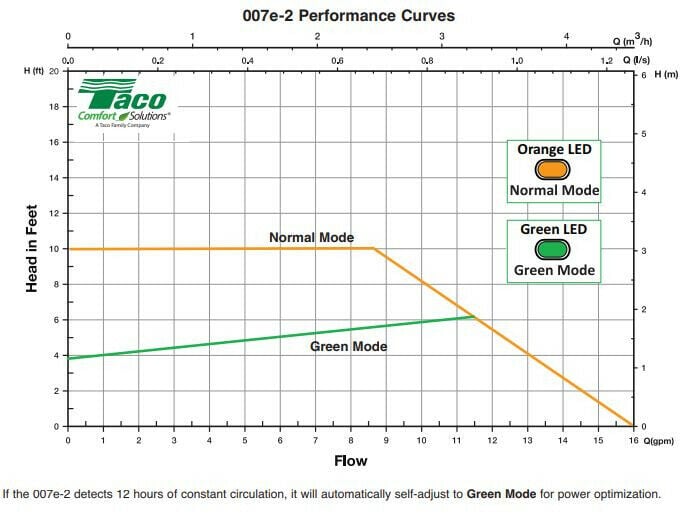
Based upon Uponor's charts, it looks like for 100% water circulating at around 110 degrees F, 10 foot of head will circulate about 1 gallon per minute through 250 feet of 1/2 inch pex at about 2 feet per second. Not asking if this is a good idea just want to understand the 007e pump. So with just one circuit of 250 feet of 1/2 inch pex hooked up to the 007e, it looks like it will push up to its 10 foot maximum and circulate that water as stated above at about a gallon per minute. Is that right? Now if another circuit is added, the pump will circulate 2 gallons per minute total and so on as you add circuits until you add the ninth 250 foot circuit and now the pump will not circulate the same amount of water but slightly less because it will not make the full 10 foot head at this flow. It looks like that at 10 circuits of 250 feet, there is just 8 foot of head available. Going back to Uponor's chart, 8 foot of head divided by 250 foot of 1/2 inch pex is .032 foot of head per foot and at 110 degrees F, that would be about 8.8 gpm moving at about 1.6 feet per second. I understand that this is an approximation, I am guessing an exact interpolation would be a calculus problem just want to know if this is a correct understanding of how the 007e operates?
Assuming this is correct, how does the pump sense the increased demand?
Comments
-
Not a calculus problem at all -- just the way pumps operate. First, step back and look at the basic 007 (without the e). This is a bog standard centrifugal pump, and is notable for (and useful because of!) a remarkably flat pump characteristic at constant speed (60 hz). Now what Taco has done is swap out the older AC motor (which will run until Doomsday, but at only one speed) for a variable speed, electronically controlled motor (hence ECM).
The pump's controls sense the flow or pressure difference, and vary the speed of the motor to reach the desired flow (there are other conditions which can be sensed, such as delta P or delta T). The 8.8 gpm at 10 feet of head is the maximum the pump with the original motor can reach. Below that head, the old pump's flow was greater; above that head, less -- the difference is that the 007e's electronics give a constant head (in normal mode) at any flow up to 8.8 gallons per minute.Br. Jamie, osb
Building superintendent/caretaker, 7200 sq. ft. historic house museum with dependencies in New England0 -
I think 1 gpm in a 250' loop of 1/2 pex @120F would be around 8' head?
1 gpm seems a bit high, the RadPad shows a suggested max. of .6 gpm in a 300' loop of 1/2".
Unless the 1 gpm is just for an example?
This journal take you through the steps of developing a system curve, overlay on the pump curve.
Also how the various delta p functions work.
https://www.caleffi.com/sites/default/files/coll_attach_file/idronics_16_na_0.pdfBob "hot rod" Rohr
trainer for Caleffi NA
Living the hydronic dream0 -
Hi there
you're right, the 007, and 007e are fundamentally variable flow, net flow is dictated by the system resistance. first step in sizing the pump, is knowing the amount of BTU's that have to get delivered to load. Next the piping has to be sized adequately to accommodate the flow rate required based on Load. quick rule of thumb for a 20 degree delta T, is approximately 1 GPM per 10,000 BTUs. the resistance through the selected length of pipe and diameter will give you the two variables necessary (Flow & Head), to size a pump. Here's where your analysis compares, the flow rate through 250 lineal feet of 1/2" pipe is the pressure drop the pump is pumping against and dictates where the pump operates on it's curve. This is true with both types as Jamie Hall so eloquently explains in this tread. There's a great video on tacocomfort.com called understanding ECM circulators. For your convenience, I provided a link.
http://www.tacocomfort.com/products/variable_speed_products/007e/index.html
great way to understand why electronically commputated motors, ECM are more efficient, in comparison to PSC type AC motors.
Please reach out to Taco Tech support at 401-942-8000 is you have additional questions regarding any Taco products.Joe Mattiello
N. E. Regional Manger, Commercial Products
Taco Comfort Solutions
 2
2 -
This weeks Taco After Dark covers this topic0
-
I am considering a Taco 007E to be paired with some zone valves in my home. I watched some videos explaining the features of the 007E, and one person said that it can sense when there is no load and shuts off. Does that mean the 007E can be powered all the time, or does it need to be wired with a relay like a traditional circulator?0
-
Hi Robert, attach is the wiring diagram off the IOM showing you can hard wire the Taco 007e or you can wire through one of our controls ZVC or SR controls. If you have any questions please call into Taco Tech Support Mon-Fri 8am-5pm EST. 401-942-8000
0 -
If I new nothing about circulatory, system head, ecm, or psc and just looked at this graph I would say that anything above 10' of restriction and the pump would move 0 gpm. Anything under 10' and the flow rate would be between 8 and 16 gpm.
Is that right?
The minimum I want going through 3/4" copper would be 4 gpm due to velocity noise. How many pro's out there lie in bed and can hear that noise and every relay etc.
Maximum 4 gpm system, minimum 8 gpm ecm
Not for me, I put one on my house and took it off the next day (velocity noise)
Getting back to work now, I'll watch the video later. Thanks taco
PS these power connections are junk and I've stopped recommending these to customers0 -
In order to understand the circulators performance curve and where it operates is also dependent upon the system curve and where the curves intersect each other. We did a webinar on this very subject a couple of years ago
Dave Holdorf
Technical Training Manager - East
Taco, Inc
0 -
Will it move less than 8 gpm?0
-
Thanks folks, I think I got it now. So wherever the system curve intersects the "curve" will determine the gpm.
Now, how do I shift the system curve left or right to dial in the desired gpm? Ball valves? Bypassing?0 -
How close do you want to get?
0 -
Theoretically a PRV can provide constant head. That pressure provides required flow when all terminal control valves are fully open. As those valves close system curve moves left to decrease flow. Is that decreased flow the flow you want?pecmsg said:How close do you want to get?
I believe that properly chosen circulator is good enough. Need neither smart pump nor my theoretical PRV setup.0 -
A good rule of thumb is 4 or more zone valves on a single speed circ, add a PAB pressure activated bypass valve. It sheds excessive flow back to the boiler or LLH. This prevents excessive flow, noise and erosion wear on the piping.
It is a parasitic valve however, in that the pump runs full speed and the valve sheds excessive flow. Sort of like driving your truck with the foot down on the accelerator, and using the brake to control speed.
A delta P circ, properly adjusted accomplishes the same, and uses less wattage.
You are basically building a flat curve circulation device.
Idronics 16 takes you through the steps to develop a system curve.
https://idronics.caleffi.com/magazine/16-circulation-hydronic-systemsBob "hot rod" Rohr
trainer for Caleffi NA
Living the hydronic dream0 -
Thanks everyone for the feedback. I just couldn't get my head wrapped around the flat portion of the "control" curve. So the gpm is where the system curve cuts through it. I think I knew that but I just needed a little bump up side the head.
I just don't want to be out here "over pumping" loops and causing noise (and errosion). I was under the impression that no matter how much I throttle down (the high side) of the pump that it would keep pushing a minimum of 8 gpm. I see now that it's not the case.
PS I've replaced more ECM circulators and blower motors in the last few years than I have in 40 or so years on the job. I think the technology is a big pain in the butt for guys in the field. But hey, it stream lines the process for the manufacturers and thats what really counts (he said in a sarcastic tone)
0 -
I'd be interested in knowing the failure of those ECM circs? Seems magnetite locks them up more than any other failure? Which isn't the circulators fault. IF they are seizing, I'd add mag seperators. If it's electronics, maybe power surges or brown outs are the failure?Sootmaster said:Thanks everyone for the feedback. I just couldn't get my head wrapped around the flat portion of the "control" curve. So the gpm is where the system curve cuts through it. I think I knew that but I just needed a little bump up side the head.
I just don't want to be out here "over pumping" loops and causing noise (and errosion). I was under the impression that no matter how much I throttle down (the high side) of the pump that it would keep pushing a minimum of 8 gpm. I see now that it's not the case.
PS I've replaced more ECM circulators and blower motors in the last few years than I have in 40 or so years on the job. I think the technology is a big pain in the butt for guys in the field. But hey, it stream lines the process for the manufacturers and thats what really counts (he said in a sarcastic tone)Bob "hot rod" Rohr
trainer for Caleffi NA
Living the hydronic dream0 -
Sketchy power connectors on the tacos. The control modules on the blower motors.0


Categories
- All Categories
- 87.7K THE MAIN WALL
- 3.3K A-C, Heat Pumps & Refrigeration
- 59 Biomass
- 430 Carbon Monoxide Awareness
- 127 Chimneys & Flues
- 2.2K Domestic Hot Water
- 5.9K Gas Heating
- 121 Geothermal
- 170 Indoor-Air Quality
- 3.8K Oil Heating
- 79 Pipe Deterioration
- 1K Plumbing
- 6.6K Radiant Heating
- 396 Solar
- 16K Strictly Steam
- 3.5K Thermostats and Controls
- 56 Water Quality
- 51 Industry Classes
- 51 Job Opportunities
- 17 Recall Announcements