Please help identify temperature sensor and diagnosis/repair

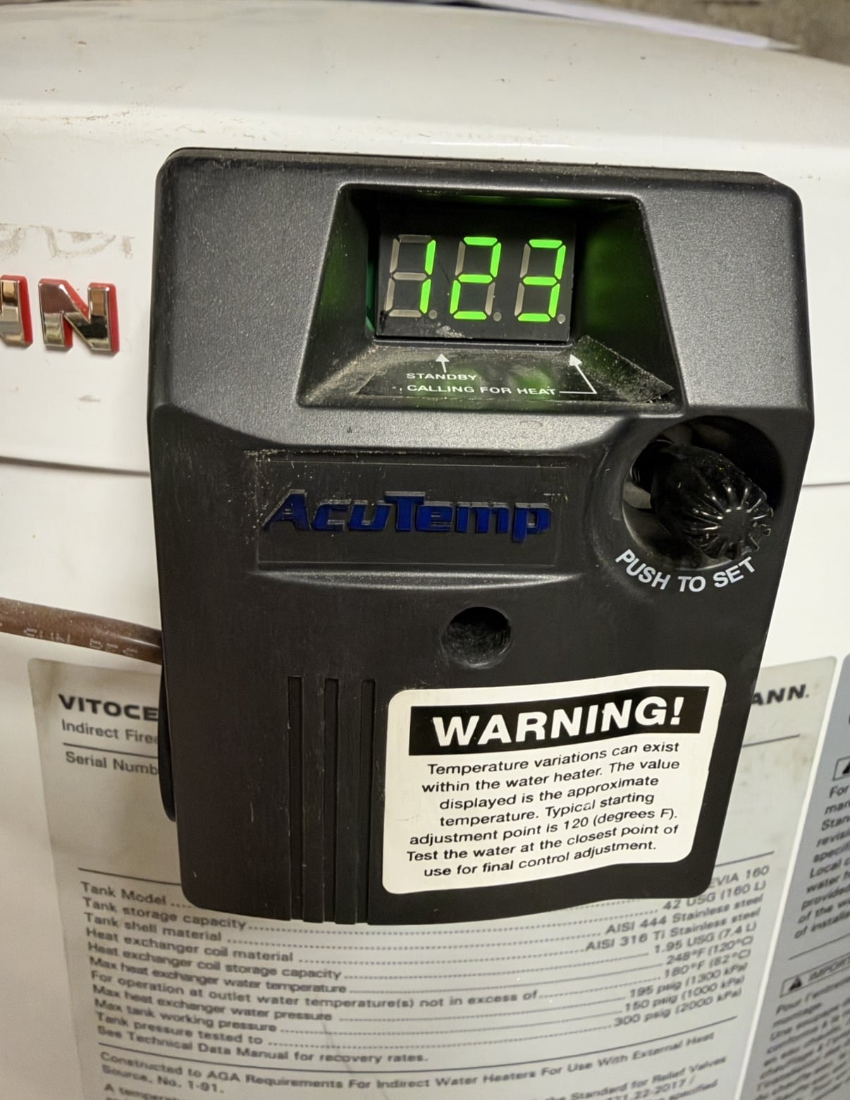
I have a Viessmann Vitocell EVIA 160 indirect water heater.
After taking a quick 7 minute shower and then doing the dishes, the water was not as hot as it usually is. I also did not hear my boiler fire up as I was washing the dishes like I normally hear.
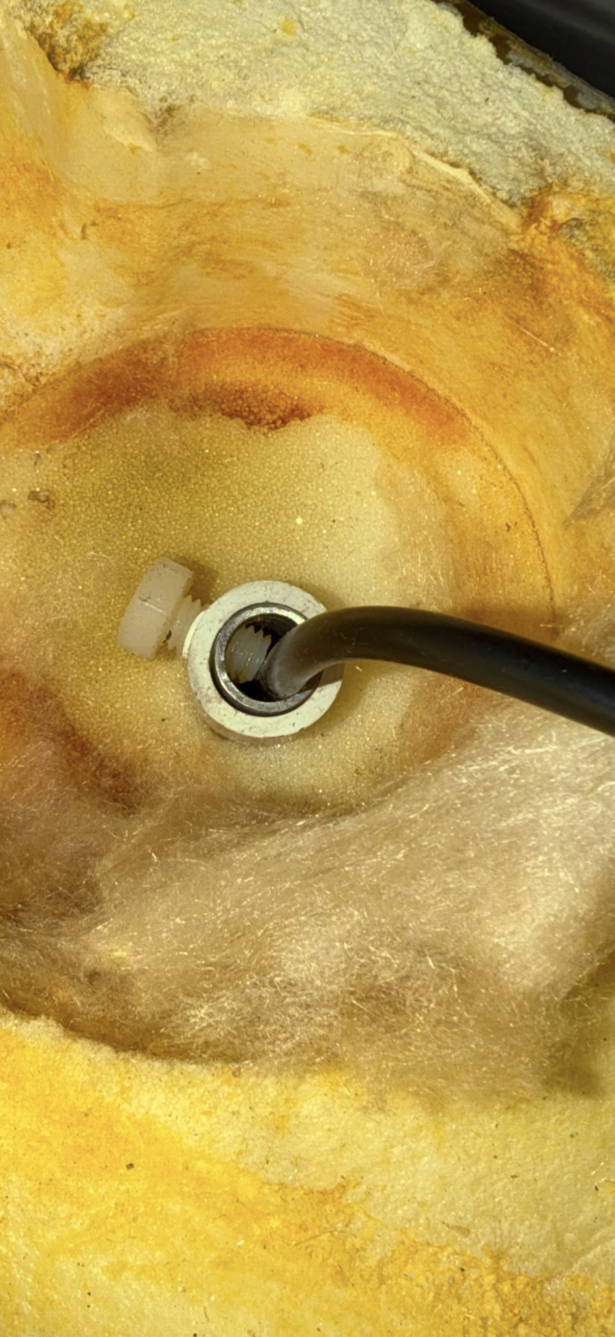
I have pin pointed the POSSIBLE issue to the temperature sensor. I removed the temperature sensor from the TS Well to see what I’m working with. It’s a black cable with a metal cylinder on the tip.
I blew on the metal tip to get it to cool down and then the boiler turned on and the valve opened. I put the metal tip back into the TS Well and the boiler shut off after a few seconds.
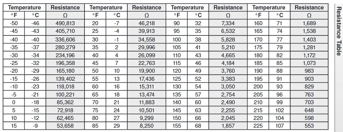
So I believe the temp sensor may just be out of spec or something. Is there a chart for me to measure resistance / temperature? I’d also like to have the part number so I can order the correct replacement.
I also confirmed the boiler was working by turning on my hydronic slantfin baseboard heat.
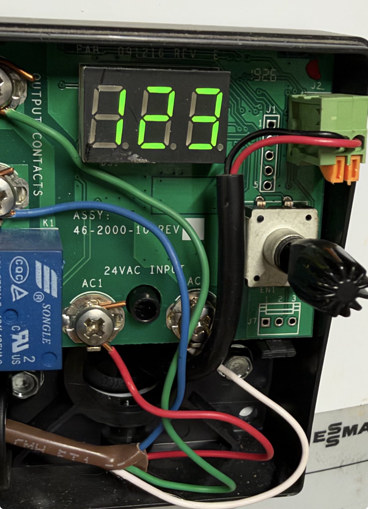
Here are some pictures. I forgot to take a picture of the metal tip.
Thank you
Comments
-
Seems that the sensor has lost its calibration, like you said. You may only need a new sensor (20K?), but here is the whole kit. Doesn't get good reviews.
What make boiler do you have?
8.33 lbs./gal. x 60 min./hr. x 20°ΔT = 10,000 BTU's/hour
Two btu per sq ft for degree difference for a slab0 -
if you don’t have the original manual, find it online
It will have the resistance chart. Do you have an ohm meter?
Hold the sensor against a cup of ice, then against a cup of boiling water to test both ends if the range
If the boiler display reads out check temperature there as you warm and cool the sensor. Then you don’t need the ohm meter
Bob "hot rod" Rohr
trainer for Caleffi NA
Living the hydronic dream0 -
Boiler is buderus g115. Thanks for the link, maybe I will try a different brand of sensor
0 -
i found the manual for my water heater but it does not state the recommended temperature sensor.
I did not know what model temperature sensor is until the previous poster found it
0 -
Hydrolevel's AcuTemp Installation Manual is impressively lame where it concerns the temperature sensor testing or replacement. Often NTC sensors 20 K or 10 K are 20,000 or 10,000 Ohms at 77 degree Fahrenheit or 25 degree C, it could be a digital sensor too.
Maybe call them.
 National - U.S. Gas Boiler 45+ Years Old
Steam 300 SQ. FT. - EDR 347
One Pipe System0 -
If the sensor is actually the issue, one like this may work, however there is not enough information to be sure.
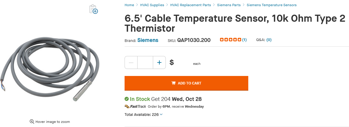
https://www.supplyhouse.com/Siemens-QAP1030-200-6-5-Cable-Temperature-Sensor-10k-Ohm-Type-2-Thermistor
National - U.S. Gas Boiler 45+ Years Old
Steam 300 SQ. FT. - EDR 347
One Pipe System0 -
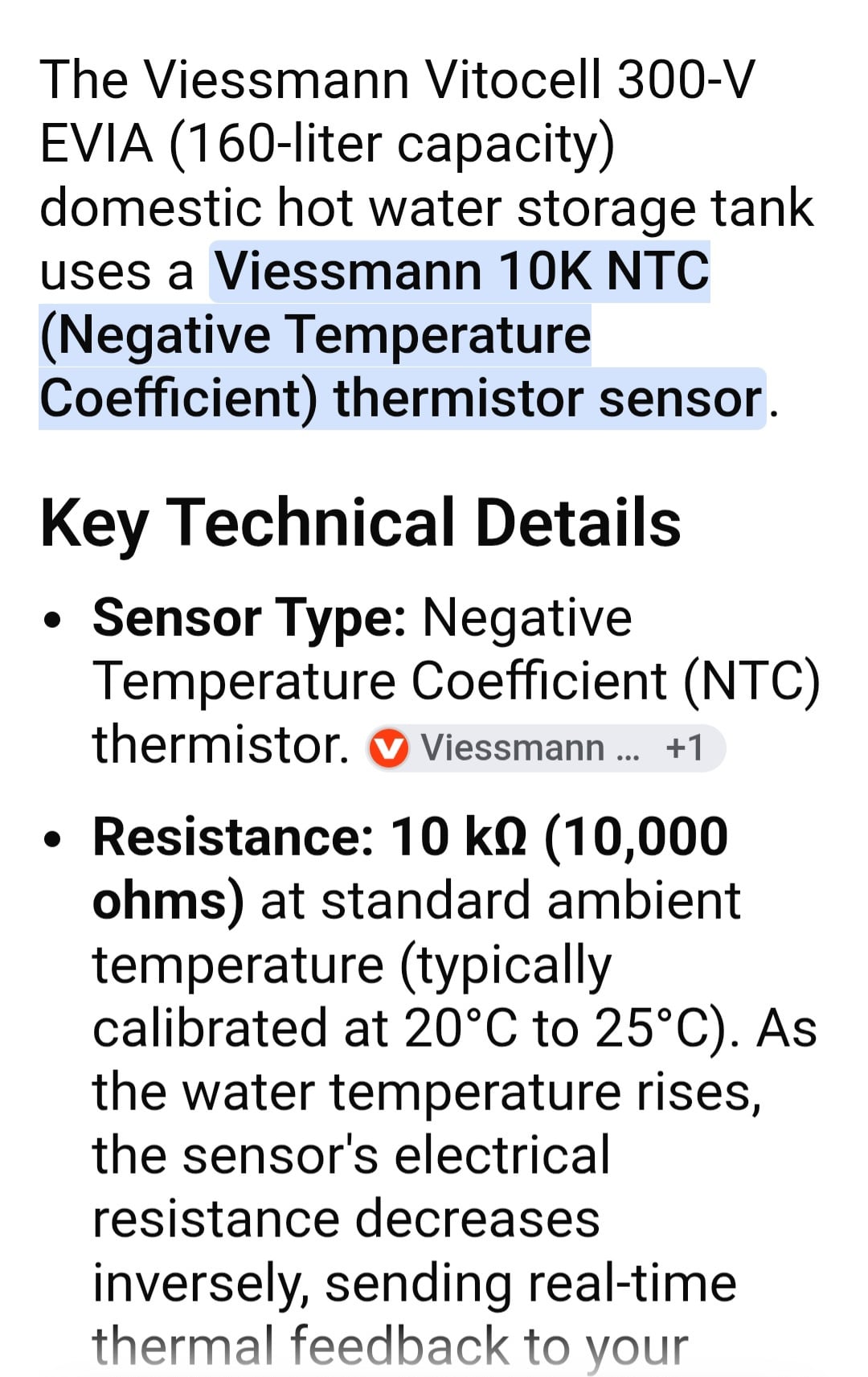
AI says its a 10K thermistor. Crank the heat to 77° and check it.
 0
-
Do these type of temp sensors only work with air temperature or can I place it into a cup of water to confirm?
Also, this test will only tell me if it’s 10k ohm or 20k ohm, correct? It wont tell me if it’s necessarily out of calibration at other temperatures other than ambient temperature?
0 -
You can put it in water and it will give you the temp with good accuracy and you can search "10k resister charts" for the numbers
Miss Hall's School service mechanic, greenhouse teacher, dog walker and designated driver
0 -
I don’t think that sensor is an immersion type. It needs to be in a well and it reads through conduction. It wants to be in contact with the well, or fastened tightly to the tank
sometimes heat transfer grease is used
It will read air temperature also
Bob "hot rod" Rohr
trainer for Caleffi NA
Living the hydronic dream1 -
However you can get the sensor to 77F, either by direct contact with water or air, it should read either 10K ohms or 20K ohms or something close. If it's off, replace it as it's lost its calibration.
You can also test it at room temperature and look up either the 10K table or 20K table to see if the reading is accurate.
8.33 lbs./gal. x 60 min./hr. x 20°ΔT = 10,000 BTU's/hour
Two btu per sq ft for degree difference for a slab0 -
have any of you actually seen a thermistor "lose its calibration"? It is just a passive component, unless it got cooked from overcurrent or an external flame there isn't much to go wrong with it other than a broken or loose wire.
10k or 20k tells you nothing other than the resistance at 25c. it tells you nothing about the curve, you either need a chart for that specific part or the thermistor constants for that part.
1 -
"10k or 20k tells you nothing" It tells you that they are NOT interchangeable for proper operation.
National - U.S. Gas Boiler 45+ Years Old
Steam 300 SQ. FT. - EDR 347
One Pipe System0 -
I don’t think there are universal sensors, best to get the correct one from the manufacturer
Bob "hot rod" Rohr
trainer for Caleffi NA
Living the hydronic dream0 -
I ordered and installed the AcuTemp model. I replaced the temperature sensor and the control unit thing.
The old temp sensor measured good according to the 10k ohm chart you guys posted. It matched the new one. But I just replaced everything.
Thanks.
 1
-
I assume that corrected the issue. It may have been the unit at fault and not the sensor probe. Although I have heard of thermistors having odd behavior at certain temperatures which makes them no longer fit for use.
National - U.S. Gas Boiler 45+ Years Old
Steam 300 SQ. FT. - EDR 347
One Pipe System1 -
I have no idea, I don't have any concrete evidence of any failure. But I already bought the thing so I figure just install it. The large amount of bad reviews stating frequent failures just made me install it as it is already 6 years old.
0 -
Well you could keep the old stuff as questionable spares. If you are adventurous the AcuTemp unit could be tested / exercised with a 20 K (20,000 Ohm) Potentiometer (like an old type volume control, a variable resistor). 20 K would get you a test range of about 50 to 225 degrees Fahrenheit.
The Potentiometer is a test substitute for the thermistor sensor probe.
From another thread, here is another way of looking at the Thermistor resistance curve.
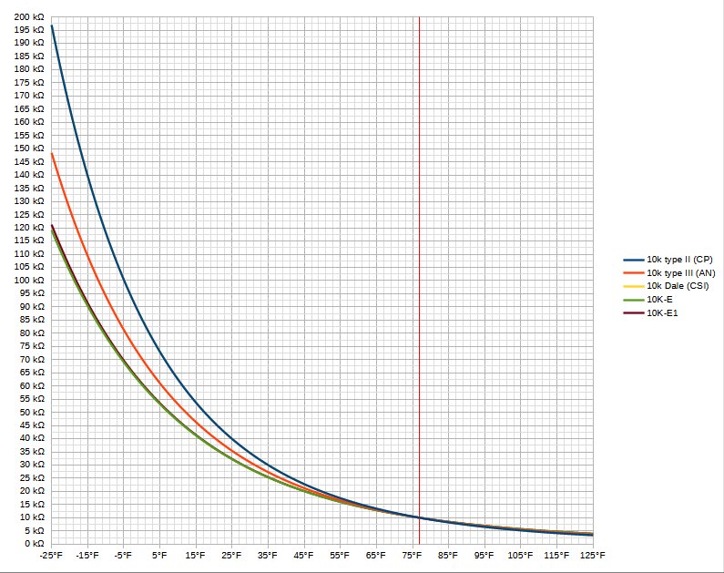 National - U.S. Gas Boiler 45+ Years Old
Steam 300 SQ. FT. - EDR 347
One Pipe System 2
-
Awesome chart there, @109A_5!
The 10k is just part of the specification, the further away from that specified point (usually—but not always—77°F/25°C), the more error you'll have. For a thermostat sensing air temperature, you'll see at most a few degrees difference using any of the 10k sensors, but for hot water you can get pretty far away from the truth. This error can't be calibrated away, a single-point 'calibration' just moves the curve around.
You said the old sensor still reads 10k at 77°? Tape the new sensor to it, put 'em in a plastic bag, and measure them both in an ice bath and a hot water bath. If they measure pretty close to each other, you're good. You can also measure the old one at several temperatures and try to guess the curve, many (but again. not all) 10k thermistors are type 2 or type 3 (other names are II / III or CP / AN).
Also, it could have just be a lousy connection that got better when you removed/replaced the sensor. That's a thing, too.
2 -
I tested the new and old sensor together a cup of warm water at around 100 degrees and 120 degrees. They read the same resistance.
I did notice that "user adjustable temperature/values" printed on the new unit is wider than the old. I forgot the exact numbers but I think the old one was something like 80F - 140F. The new one was something like 50F - 180F.
0 -
The wider temperature range is probably just a embedded software update. More data points in a look up table to compare with the ADC (Analog to Digital converter) data.
National - U.S. Gas Boiler 45+ Years Old
Steam 300 SQ. FT. - EDR 347
One Pipe System0 -
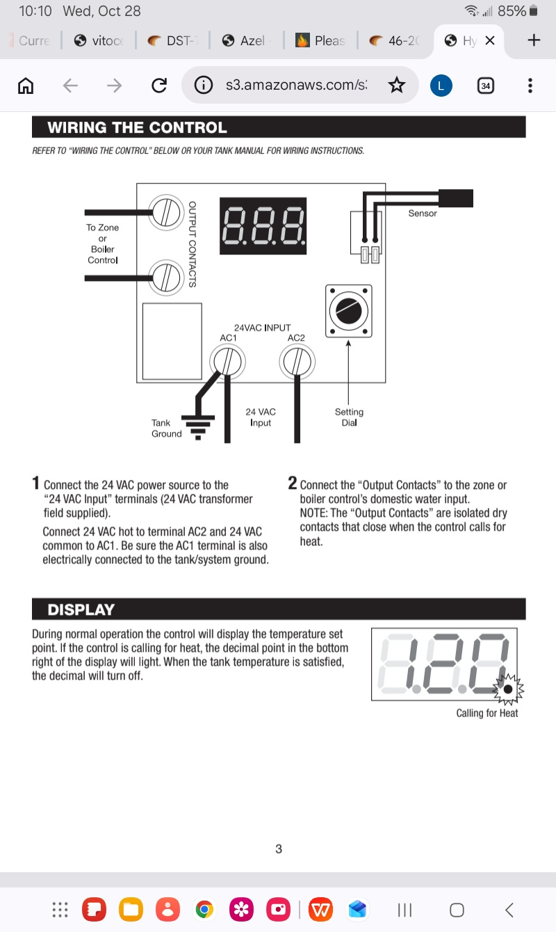
A few years back, I took over maintenance for a property that had about 28 of these controls on Weil Maclean indirect water heaters. About once a month , we would have these controls fail or just plain act odd , and I would have to replace them. So I called the manufacturer, And what I was told , these controls are very fussy on power supply. Terminal AC1 has to be connected to the C terminal of the transformer. Terminal AC2 has to be connected to the R terminal of the transformer. Tech support also told me this control should be the only item on the transformer. And the AC1 terminal should be grounded to the tank. If the transformer terminals are not marked, Take a voltage reading on the transformer terminal to the ground and the one with the lower voltage should be the C terminal. I discussed this with my electrician, he said it sounded right , but he didn't like the idea of grounding it to the tank. I put every control on its own transformer wired to the terminals as directed and haven't had a problem since. ( Never done the tank ground though)
 0
-
@Lyle {pheloa} Carter Building something that is that fussy and/or flaky and selling it to the public should be criminal. AC1 or L1 is most often the Ungrounded Hot wire, AC2 or L2 is often the Neutral or grounded side of the 120 / 24 VAC power source.
So even their resolution is goofy.
National - U.S. Gas Boiler 45+ Years Old
Steam 300 SQ. FT. - EDR 347
One Pipe System0 -
@Lyle {pheloa} Carter Curious, maybe it was not tried, once they failed was the power cycled on any of them ? If so what happened ?
National - U.S. Gas Boiler 45+ Years Old
Steam 300 SQ. FT. - EDR 347
One Pipe System0 -
Yeah, I recognized it right away. There's a few others, in more useful ranges, too.
One of these days I'm going to make a graph that shows the error when the wrong sensor is used. It's a pet peeve of mine, "10k" is not enough to get the right sensor unless it's only going to be used at 77° ± a few degrees.
0




Categories
- All Categories
- 87.9K THE MAIN WALL
- 3.3K A-C, Heat Pumps & Refrigeration
- 60 Biomass
- 430 Carbon Monoxide Awareness
- 135 Chimneys & Flues
- 2.2K Domestic Hot Water
- 6K Gas Heating
- 124 Geothermal
- 170 Indoor-Air Quality
- 3.9K Oil Heating
- 80 Pipe Deterioration
- 1.1K Plumbing
- 6.7K Radiant Heating
- 397 Solar
- 16.2K Strictly Steam
- 3.5K Thermostats and Controls
- 56 Water Quality
- 51 Industry Classes
- 51 Job Opportunities
- 18 Recall Announcements