Picking up after my Pa (a one pipe hydronic loop).

I lead with my questions followed by the context. (Apologies, I find it next to impossible to be brief.)
Here is where I need help:
- My risers & return drops are approximately 9 feet. Will it suffice to use one venturi tee on the return side of each rooms circuit?
- Do I need a cast venturi tee? Some are rough castings everywhere except the pipe sweat surface. (I expected at least the reduced opening would also be machined for predictable performance). Perhaps I'm too particular!
- I'm tempted to use 3/4 x 3/4 x1/2 Tee w/ a NIBCO venturi insert. Anyone have experience opinions about this option? If I go this option I'll be scribing the standard tee to indicate the insert & it's direction.
- I have pipe chases where the supply and return for adjacent circuits are co-located. I put the return venturi tee 16 inches prior to the pipe chase and the next room's supply tee (3/4 x 3/4 x1/2, no venturi) 16 inches after the pipe chase. -Is this much separation necessary (advisable)? Alternatively, is it better to place the venturi at the pipe chase and the supply some distance downstream? What is the recommended separation distance?
- I'm working up circuit distances in pipe equivalents…
- These distances will inform decisions about whether more than one venturi is required in a circuit, right?
- The circuit distances are from the boiler supply manifold to the boiler's return manifold, correct? (not just the 1/2" branch and the radiator length)
Would really appreciate some experienced guidance. Thanks in advance for weighing in!
Context:
I'm in the midst of adding the 2nd floor zone to the heating system in my childhood home here in New England. There were 3 bedrooms, a half bath and seven of us on that floor(and more down below). In the winter the interior of the double pane windows would ice up as there was either a Tilly kerosene heater, or a shoe box sized electric heater to supplement convection up the stairwell to "moderate" the temperature. -We all survived.
I've found my Dad's plans for a proper heating system (boiler size, radiator placement (cast iron Base-Ray), riser & down flow locations as well as piping (3/4" copper -main loop, 1/2" copper branches) etc.
I also found some of the difficulties he ran into which certainly contributed to the system never being completed. (He mounted some of the Base-Ray radiators, installed underfloor piping, dropped some risers to the basement, then stopped.)
His design called for a 12 ft. run of radiator in each of the bedrooms. Two of the rooms are 11' x 12'. Hence no room for valves or fittings to pipe those radiators.
Now 60 years later I'm finishing up. Fortunately he purchased all the radiators for the system. Unfortunately 16 ft. of uninstalled sections of radiator were left outdoors and had to be scrapped. Also unfortunately, but predictably, the Base-Ray castings have changed so old & new won't mate to each other. But, you can plumb old & new end units together (just not intermediate units).
To solve the space issue, I plan on placing a 24" panel on the adjacent exterior wall and using Burnham's 10.25" 90 degree compression piping to connect the remaining 10 ft.
It seems to work (in my head and on paper). But, I don't know what I don't know. A somewhat precarious position. If you can reassure me that I'm walking parallel to a cliff and not toward it, I'd be most grateful !!
Jack Spade
Comments
-
There are quite a few steps. Perhps you Pa did that for the original design?
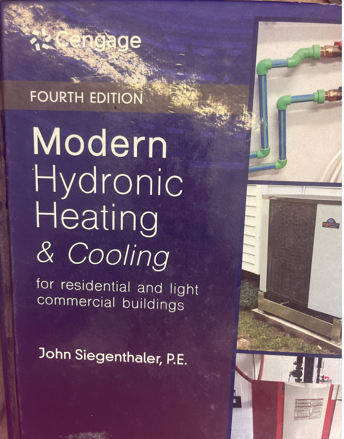
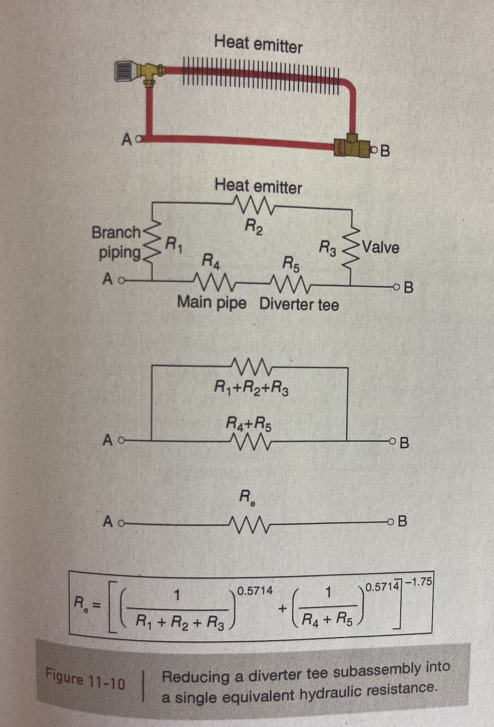
Maybe get a copy of this on Amazon and give it a read to avoid a system that doesn't do what you expect.
 Bob "hot rod" Rohr
trainer for Caleffi NA
Living the hydronic dream1 -
Is there any reason you couldn't pipe the second floor as a separate zone off the boiler with separate supply and return? If you do separate supply and return or home run it will eliminate a lot of variables and a separate zone will allow the first and second floor to be independent since they will never have the same heat loss at the same time. You could put balancing valves in the basement if you don't have room for fittings at the baseboard. You could also feed them with 1/2" oxygen barrier pex fished up through the building.
0 -
Mattmia, Yes the plan is the second floor as a separate zone. Not sure if what you suggest "do separate supply and return" is different from existing plan which has a dedicated 3/4" copper loop in the basement (adjacent/parallel to the black iron loop that serves the 1st floor), it's own thermostat, and four branch circuits for each 2nd floor room.
0 -
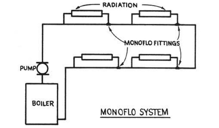
if you are going to pipe a whole new zone, use a layout that is more forgiving of not getting the math exactly right. monoflo saves some pipe but you have to get the math right for it to be even or even for it to all heat at all.
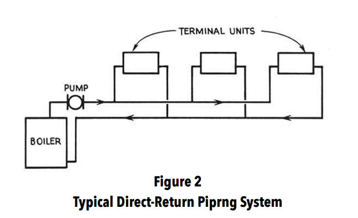
pipe the new zone as direct return:
or reverse return:

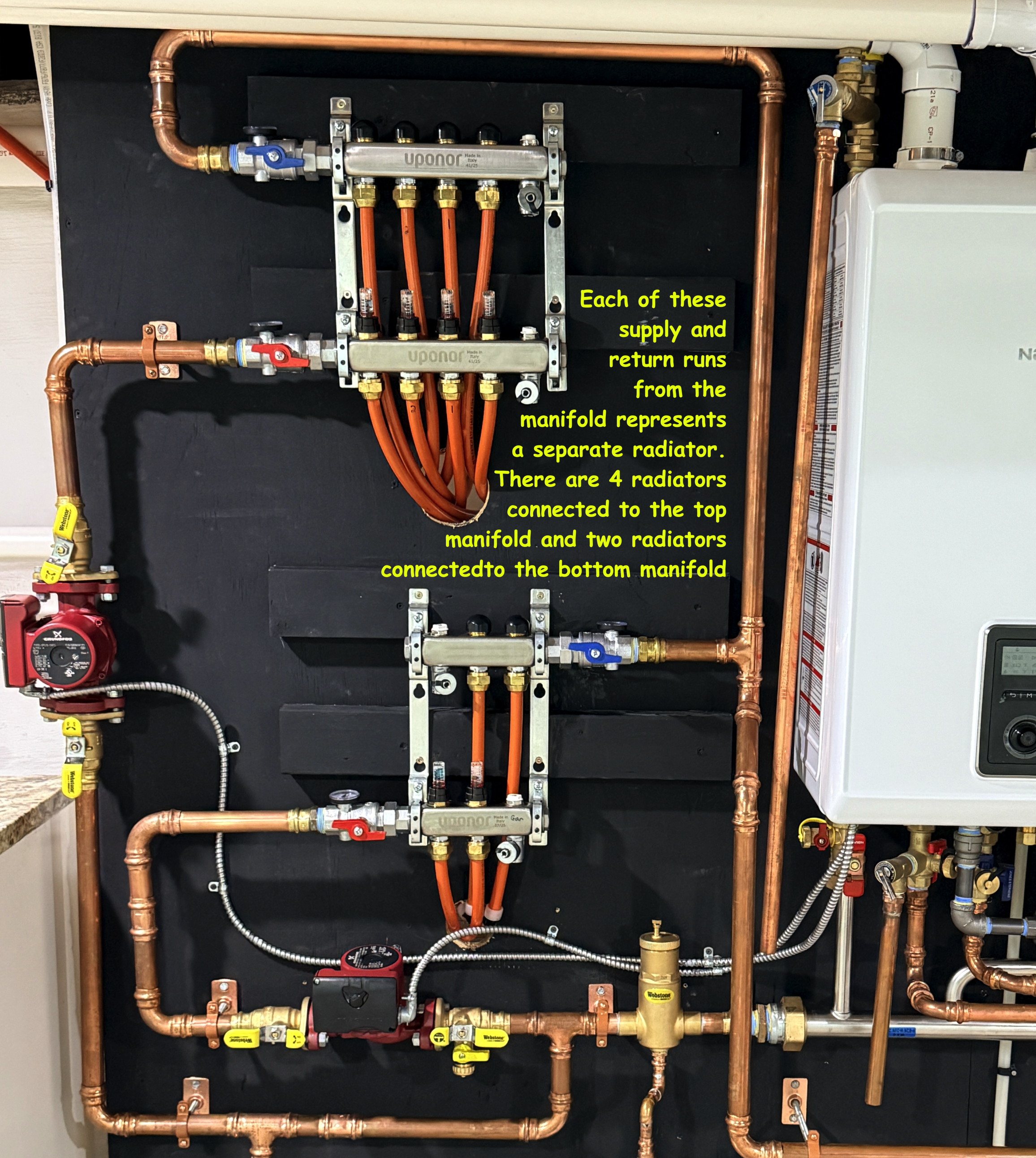
or a home run system to a manifold:
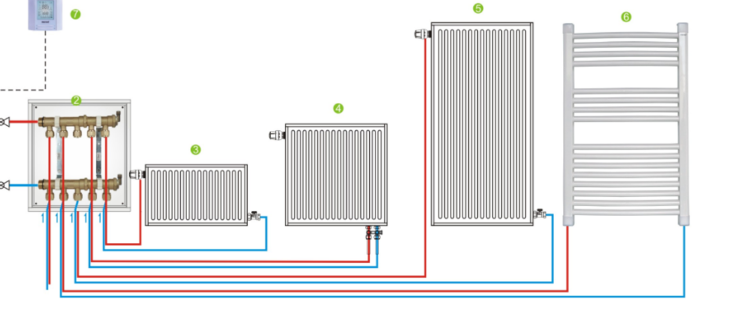
instead of monoflo:
 0
0 -
A two-pipe parallel system eliminates many of the variables that need to be overcome when designing a one-pipe Monoflo® system. There is also a much simpler series-loop design if your radiators are 3/4-inch copper tube with aluminum-fin baseboard radiators.
The other option is a home-run system, which is somewhat like a parallel system, except the main supply and return piping is very short and the individual branch runs to each radiator are relatively long.
Sometimes it is easier to understand the differences by looking at a simple visual diagram.
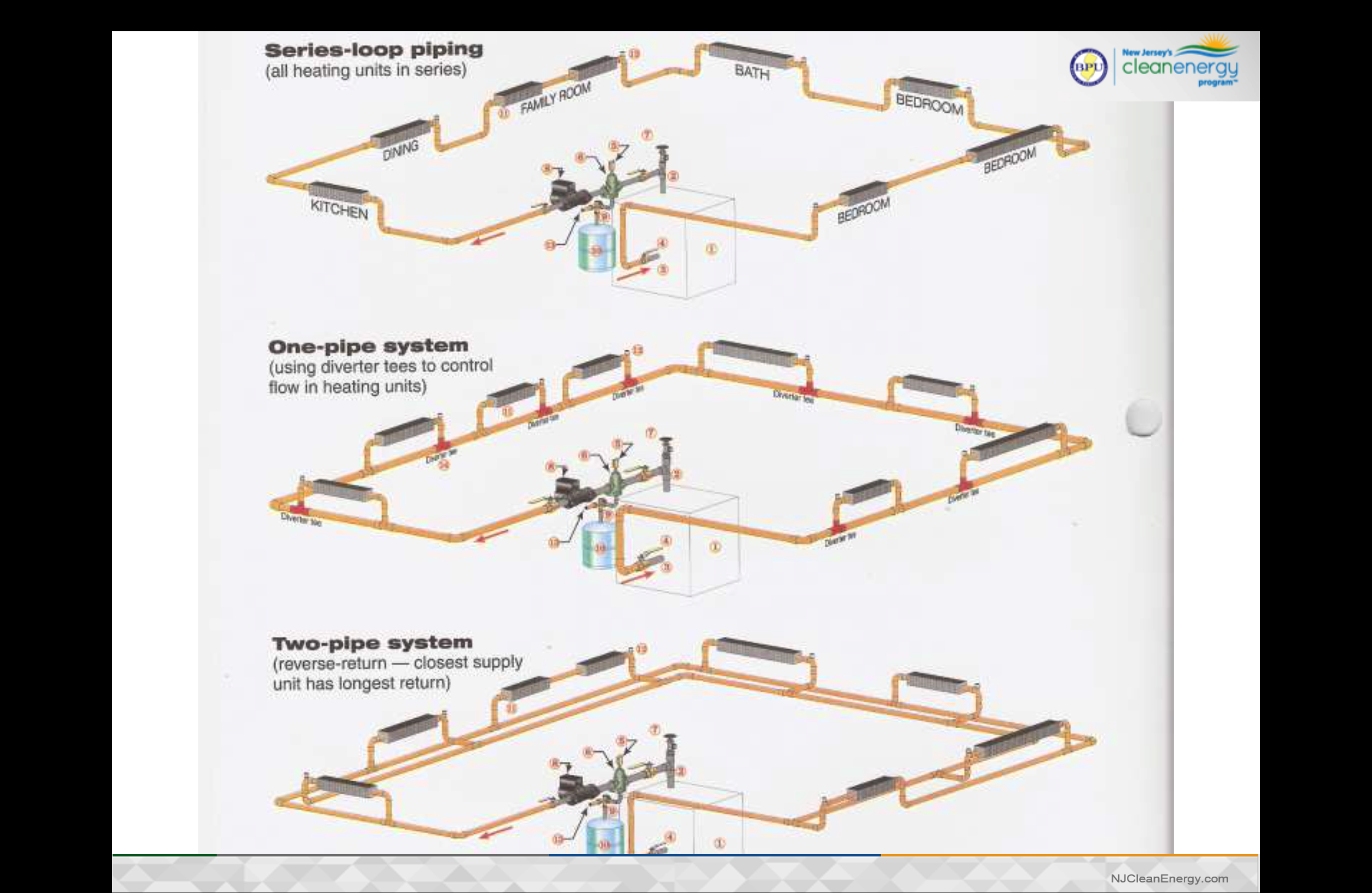
Top is a series-loop system.
The middle is the one-pipe Monoflo® design, where one main pipe circles the basement and returns to the boiler. All of the supplies and returns are connected to that one main pipe, with a diverter tee on each return. The diverter tee creates a restriction that directs some of the heated water through the radiator, while most of the flow continues straight through the main.
The bottom is a two-pipe parallel system, where all of the supplies are connected to one pipe from the boiler supply, and all of the returns are connected to another pipe that goes back to the boiler return.
The system shown in the illustration is a reverse-return system, but there are many systems with a direct-return design, where the first supply connection off the boiler is also the first return connection back to the boiler.
This is how many older gravity heating systems, which operated without a circulator, were designed. Once you add a pump to move the water through the system, that type of piping can become unbalanced.
The home-run system has the supply and return manifolds located in the boiler room near the boiler. All of the individual supply branch piping is connected to the supply manifold, and all of the individual return branch piping is connected to the return manifold.
Each radiator or heating circuit has its own separate supply and return run back to those manifolds.
Edward Young Retired
After you make that expensive repair and you still have the same problem, What will you check next?
 1
1

Categories
- All Categories
- 87.8K THE MAIN WALL
- 3.3K A-C, Heat Pumps & Refrigeration
- 59 Biomass
- 430 Carbon Monoxide Awareness
- 133 Chimneys & Flues
- 2.2K Domestic Hot Water
- 6K Gas Heating
- 124 Geothermal
- 170 Indoor-Air Quality
- 3.8K Oil Heating
- 79 Pipe Deterioration
- 1.1K Plumbing
- 6.7K Radiant Heating
- 396 Solar
- 16.1K Strictly Steam
- 3.5K Thermostats and Controls
- 56 Water Quality
- 51 Industry Classes
- 51 Job Opportunities
- 18 Recall Announcements