Two pipe buffer - Placement of Large Pipe ?

System schematics are one thing, placements and piping is another.
What are the drawbacks of placing the Large Pipes somewhere other than directly onto the buffer tank ports ?
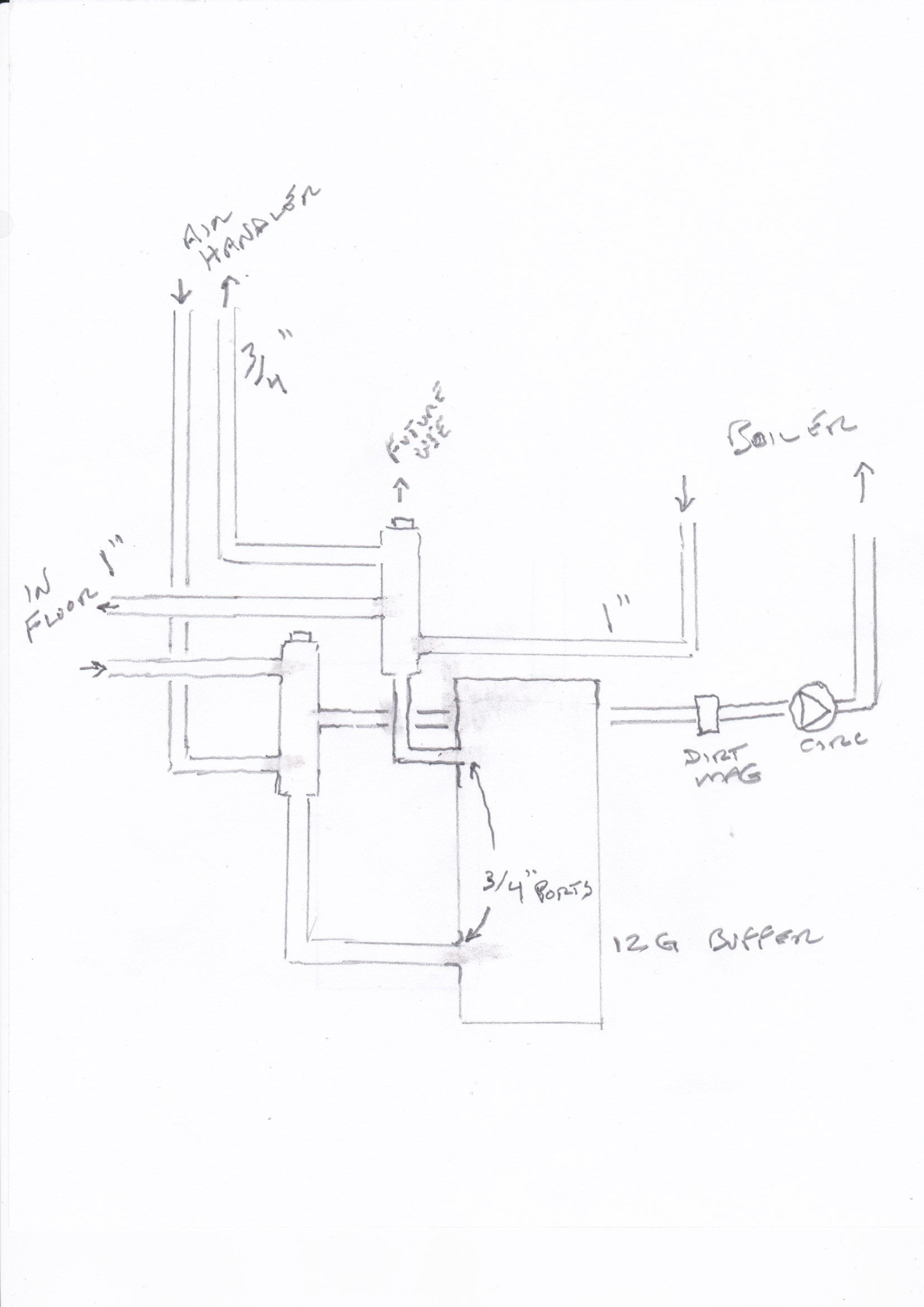
I would prefer to mount my Large Pipes vertically and closer to the wall. This would reduce stress on the buffer tank ports as well as leave the piping a bit more open to future changes of buffer tank. Planning on using 1.5" tees for the Large Pipe.
Currently in building maintenance.

Comments
-
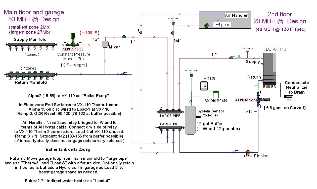
Well… in your sketch it appears that the "large pipes" are manifolds; they could — in principle — be placed anywhere. The idea is that they allow separating the flow from one pipe into many — or vice versa. In the more complete diagram (which I presume is the designed system) I see several problems with the overall arrangement, and I'm rather led to wonder if perhaps you have misunderstood the function of the "large pipes" in other systems, where they are not only manifolds, but hydraulic separators allowing the flow rates in the boiler loop to be decoupled from that in the heating loops although that will happen as the buffer tank is connected between the supplies and the returns.
The expansion tank should be on the line from the return manifold to the boiler, as close to the pump on that return as is reasonable.
Br. Jamie, osb
Building superintendent/caretaker, 7200 sq. ft. historic house museum with dependencies in New England 1
1 -
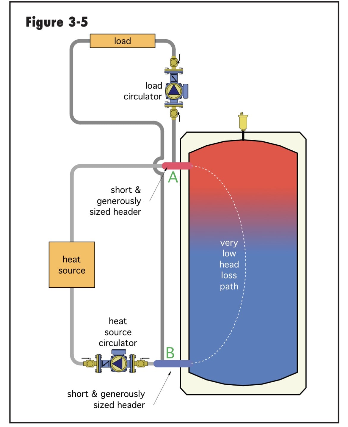
Maybe a better definition of "generously sized header. The goal is very low flow velocity in that short large section of pipe. Ideally less than 2 fps. So that close to tank piping and the tank itself presents very little head loss.
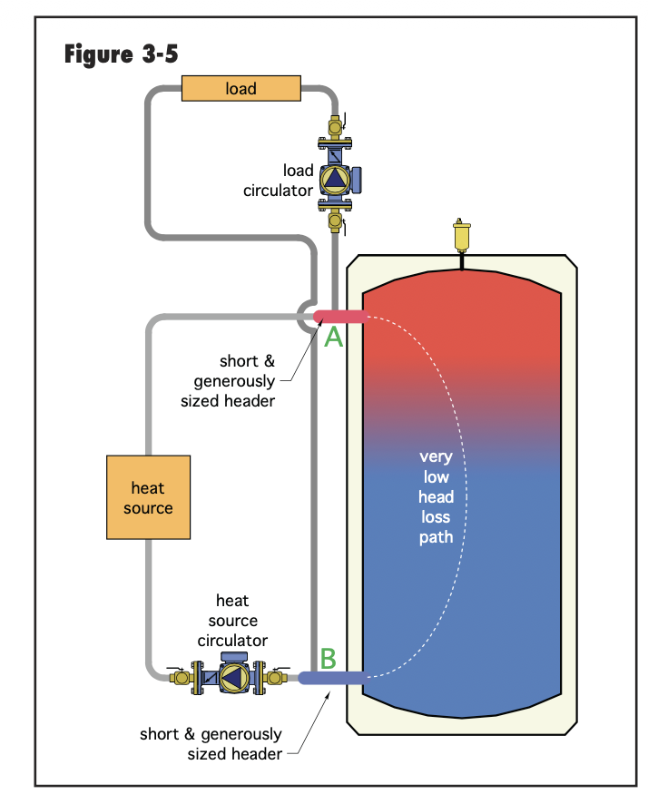
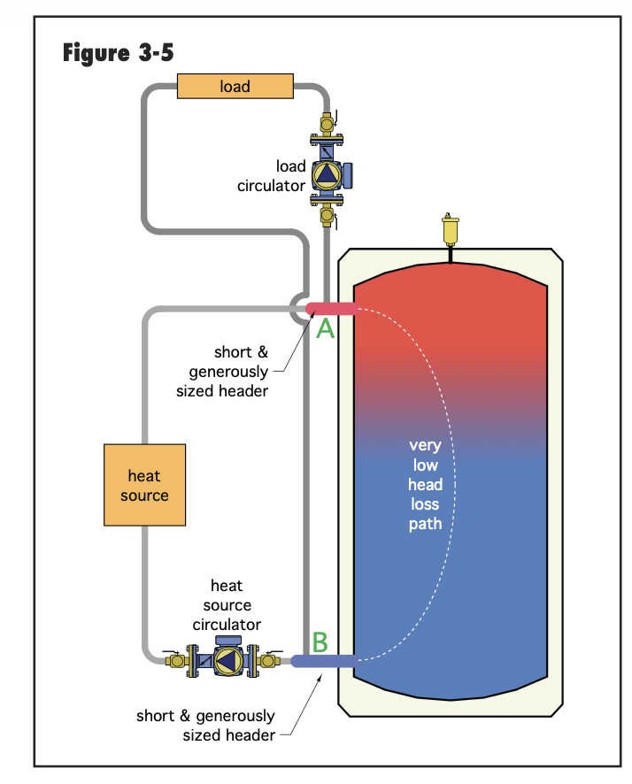
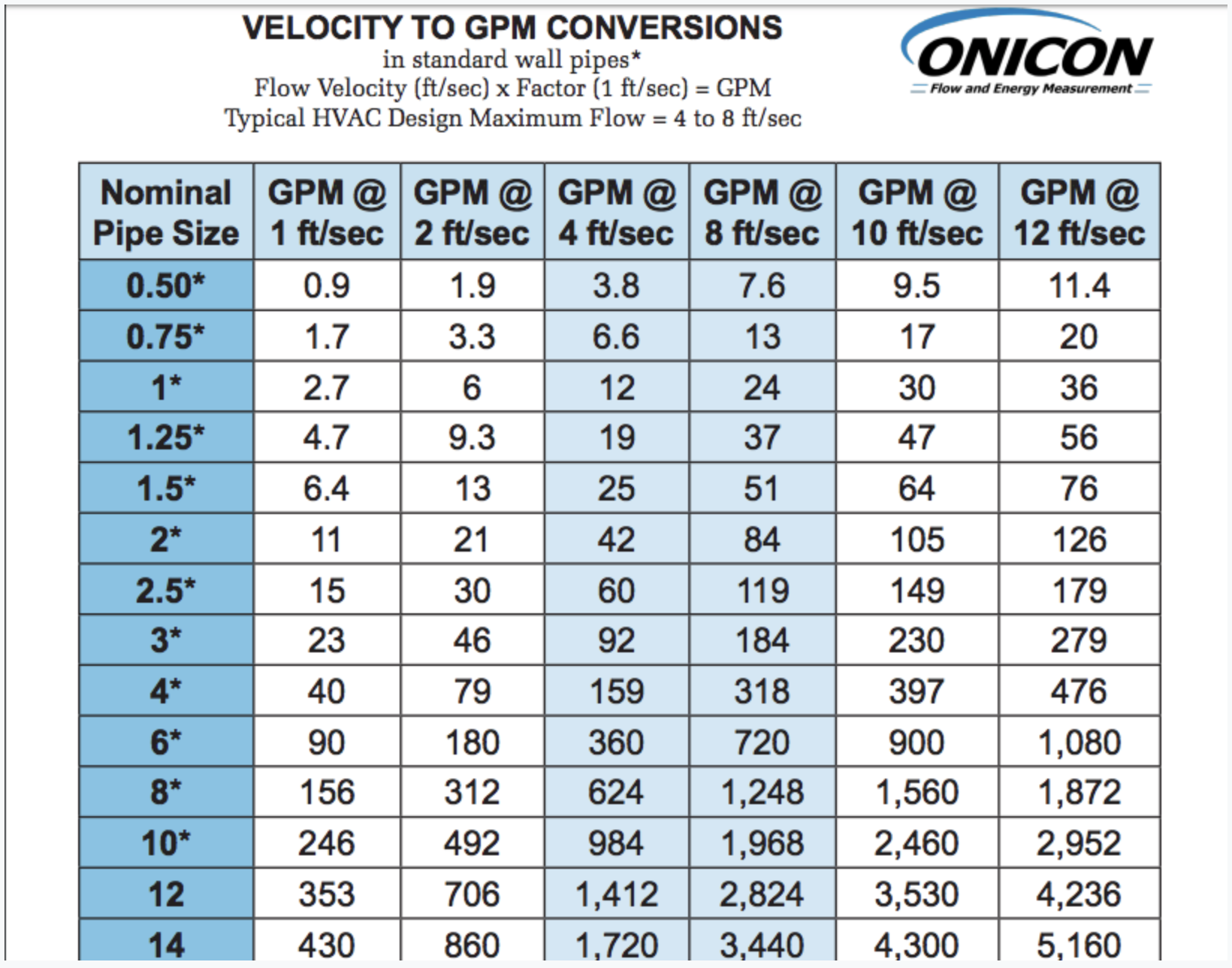
So determine the total gpm at that point. Then look at the flow tables for pipe, or tube.
Lets say you have a total of 8 gpm. You could flow up to 9.3 gpm in 1-1/4 pipe and stay in that 1- 2 fps window. No harm in going larger.
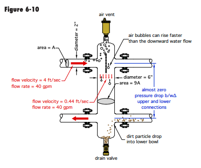
Caleffi hydraulic seps are designed to keep the flow velocity in that chamber, "generously sized pipe" below 2 fps.
This assures flows from various pumps and variously sized pumps do not interfere with flows.
 Bob "hot rod" Rohr
trainer for Caleffi NA
Living the hydronic dream0 -
@Jamie Hall I think I had originally thought to attach the expansion at the buffer as it is the point where all three circs are pumping away from. I can alter the plan to attach it and the Axiom fill box to the return line before the Dirtmag if that seems like a better location. The vent is probably best on top of the buffer, I think (reusing the top anode port).
@hot_rod My boiler loop will flow 6-7 gpm and the load loop would be anywhere from 0.5 to 4 gpm. At 4 , the excess flow (unused boiler flow) would be 2-3 gpm. If only one zone was open at 0.5, the excess would be 5.5-6.5 gpm. Hopefully Im looking at this the right way ?
So if I made the Generous Header with 1.5" tees and placed them on the back board across from the buffer ports, then stung out to the ports with <12" long 1" pipes, it might be close to workable ?
30+ yrs in telecom outside plant.
Currently in building maintenance.0 -
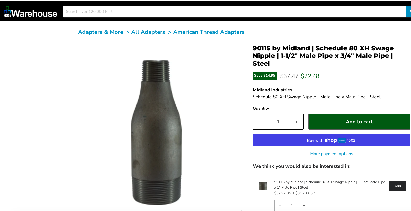
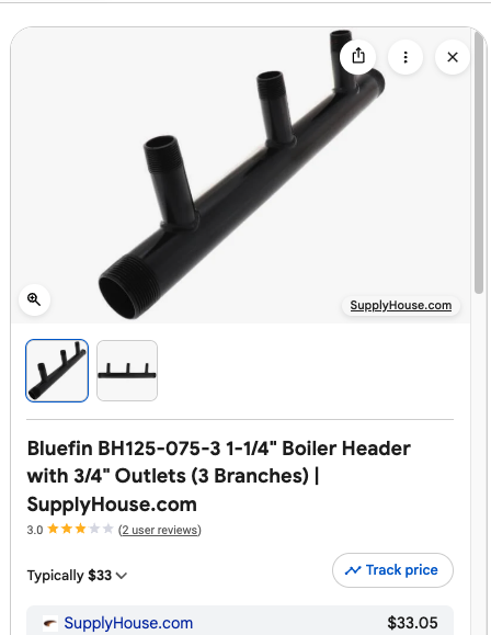
Ideally a tank with a 1-1/4 or 1-1/2 ports.
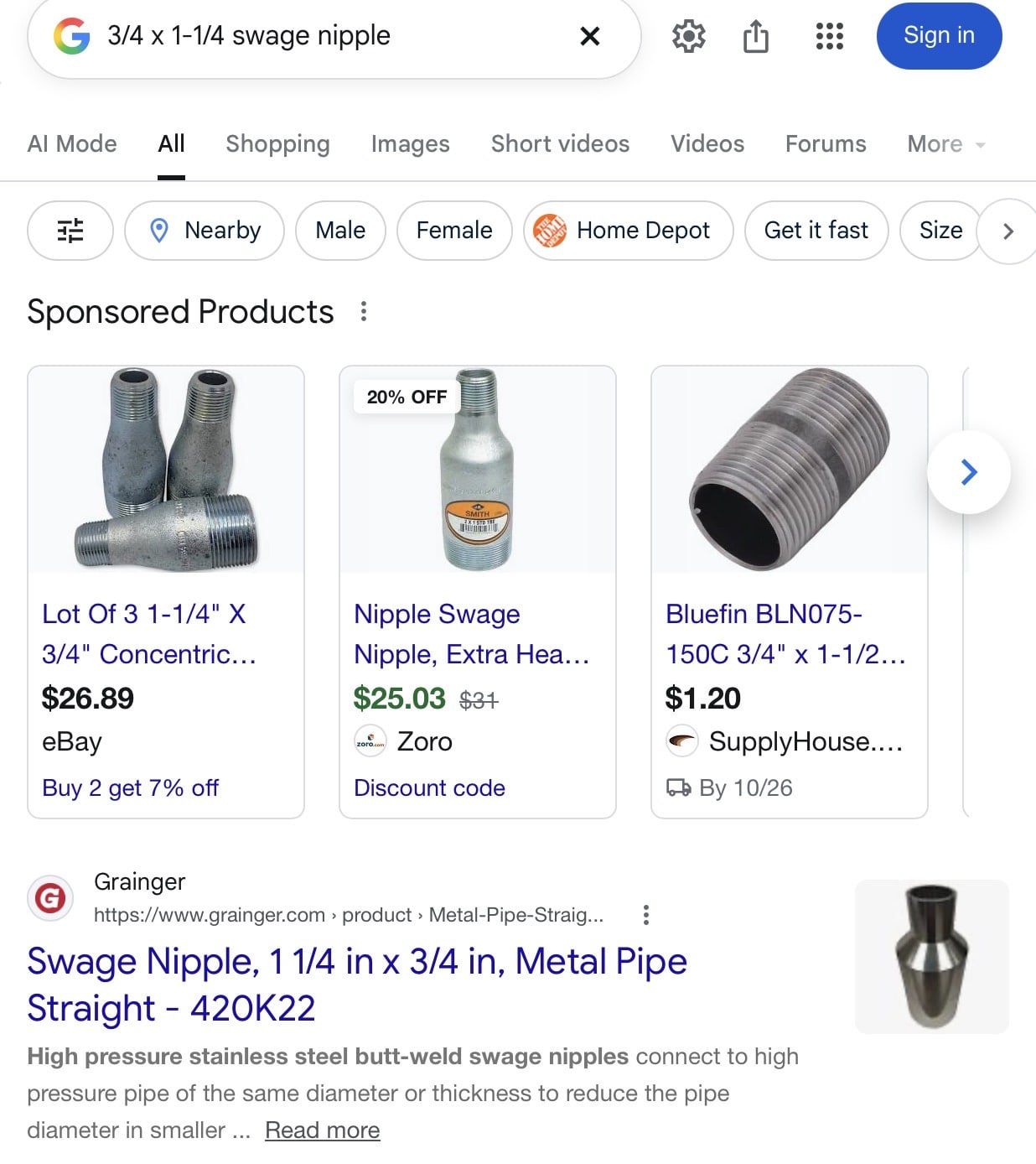
If not these swage nipples make a nice increaser. Screw the 1-1/2 tees right onto it, close nipples between them, it for a short, fat header.
Connection for the HP, air handler, radiant, maybe a spare.
Expansion tank could be on any of the 3 ports as the whole tank becomes the PONPC. On the upper header where the pumps locate works well.
The tank can mount anywhere, just the connection needs to be at the manifold, pex to the tank location.
I doubt you can build a header with tees and nipples for the price of a "speedy header"? They come in an assortment of sizes.
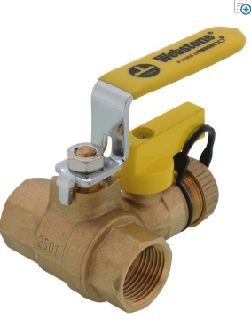
Connect the header to the swage nipple on the return with this valve. It becomes a coupling and the purge/fill port for all zones
 Bob "hot rod" Rohr
trainer for Caleffi NA
Living the hydronic dream1 -
No luck on swage nipples around here. 1.5" tees and a coupler will have to do , but at least I'll hang it off the tank. I'll find a wall bracket to hold the weight of the Large pipes.
Took the heater/buffer out of the box today. Lo and behold it has both top and side ports.
I briefly thought of the "3 pipe" approach, but I think it might not work due to the 2ft long dip tube on that Cold top port.
Also discovered that the T&P hole, where my buffer sensor is going, it at the same exterior level as the side Hot port. (the diagram showed it closer to halfway down the tank). On the upside, the side Hot port apparently has some bent tube internally to keep the pickup at the very top of the tank.
So, the sensed setpoint is going to be physically higher in the tank. Is the solution to bump the setpoint T up a bit ?
30+ yrs in telecom outside plant.
Currently in building maintenance.0 -
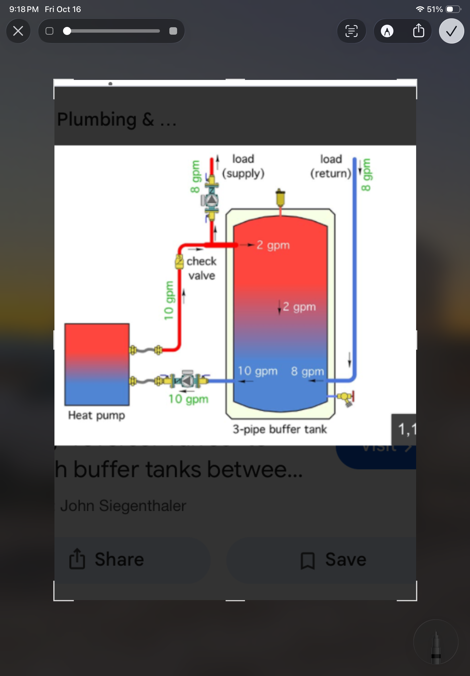
You just need 3 side connections for a 3 pipe arrangement. It doesn’t need to be on the top if the tank.
While a sensor in a well is ideal, you just need the sensor pressed against the side of the tank, if there is any opening mid way?
Is it a foam insulated tank? I have taped a sensor to a wire rod and slid it down to mid point.
 Bob "hot rod" Rohr
trainer for Caleffi NA
Living the hydronic dream0 -
Ok, I'll stay with the 2-pipe method in the 2 side ports and forget about that extra top port.
I might be able to tunnel a fiberglass rod down from the T&P skin opening, then work a sensor down in there. That will be my plan B - once it gets cold out, Im going to track data points with strap-on pipe sensors and the info from the boiler itself, while experimenting with different things. I could get a second sensor to push down there and compare the two temp readings concurrently (using an ohmmeter).
30+ yrs in telecom outside plant.
Currently in building maintenance.0 -
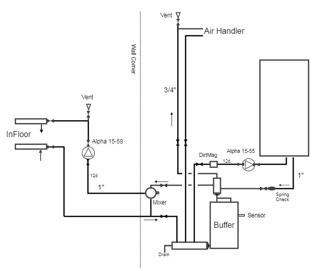
BTW, thx for posting that last graphic. I forgot to allow for a spring check on the supply line between boiler and buffer. The supply house I use should have them. I see some with a 0.5psi 'crack' rating which should be good.
In Idronics 17 fig 4-1 , they show a buffer with a sensor close to the top/hot ports. I think they indicate that this makes the most of your heat as it doesnt restart the boiler until the outlet is about to run out of desired supply temp ? I plan on a 25deg delta, plus this boiler control can modulate on a target rise of degrees/hr, the mass of water / gpm / min modulation dependant of course. It measures the f/hr between input temp and buffer temp, I suspect.. although you can select both "water from" and "boiler from" sources in config. Gonna be learning about this machine for a while I bet.
BTW - wife says the other day - why cant we just have a normal heating system like everyone else ?
Some people dont want the Science, they just want to watch the Rocket.
So, when you use a water heater as a buffer, would they not possibly include check valves (anti heat loss) ?
My side ports are pex lined (yay.. smaller water tubes) and I see no checks. I stuck a pencil in and can feel a distinct curve upward on the upper port and downward on the lower port. Could there be checks on the inside end of those curved pipes ? That would be crazy, no ? I would expect a check to be right up front.
Do I have to cap the upper port, attach garden hose to the drain fitting, and see if water flies out of the bottom port ? Im going to put unions on the 6 pipes going to the buffer, so not impossible to fix as issue later.
30+ yrs in telecom outside plant.
Currently in building maintenance.0 -
I think most all water heaters have some sort of heat trapper nipples. At least the top feed ones.
The tanks with both top and side taps, the side taps are generally just connections, no special nipples.
Depending on wherein the tank the side ports are, they may have a curve up and down tube. You should see with a flash lite, or the manual may have a picture descriptionThe drain port is usually at the lowest point also.
If you have an electric tank a 1” male NPT will fit the element port.
Which brand and model number tank do you have?
Bob "hot rod" Rohr
trainer for Caleffi NA
Living the hydronic dream0 -
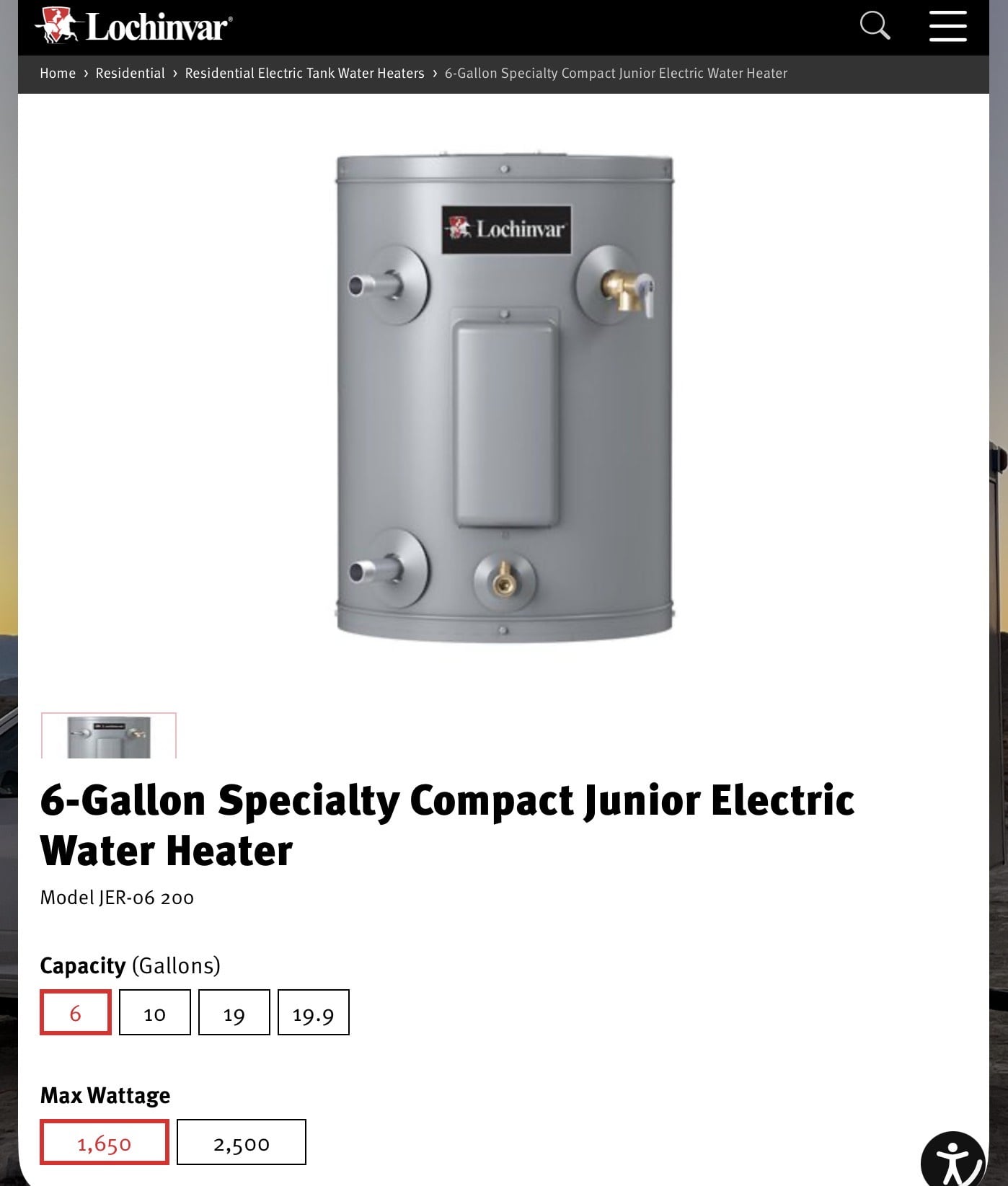
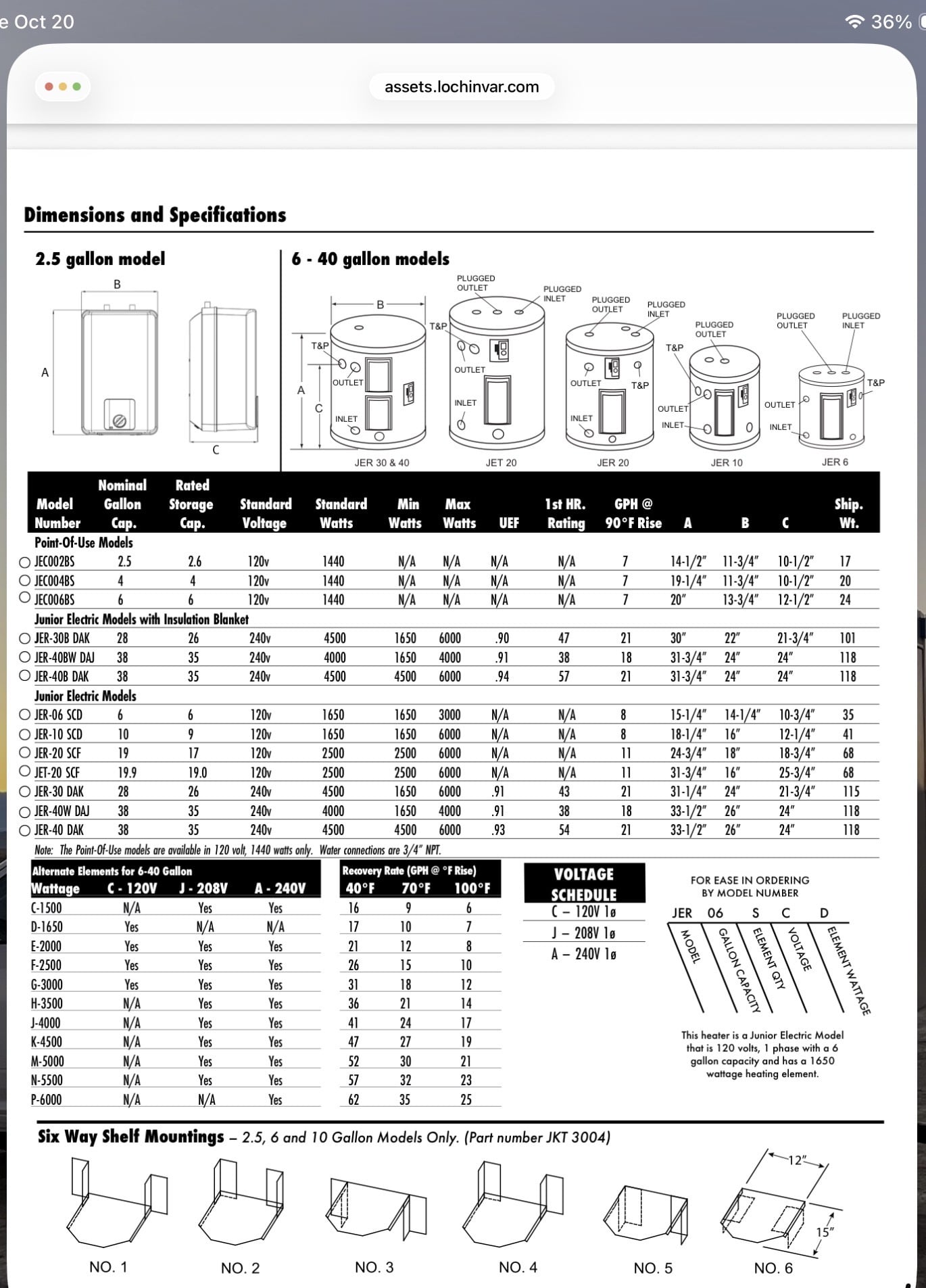
here is the tank I have used, both 6 and 10;gallon.
Other piping options are the drain and T&P port. Those will not have dip tubes.
Anode rods are typically on top, that could be removed for a top 3/4 connection. Now you have a text book 3 pipe option😏
 Bob "hot rod" Rohr
trainer for Caleffi NA
Living the hydronic dream0 -
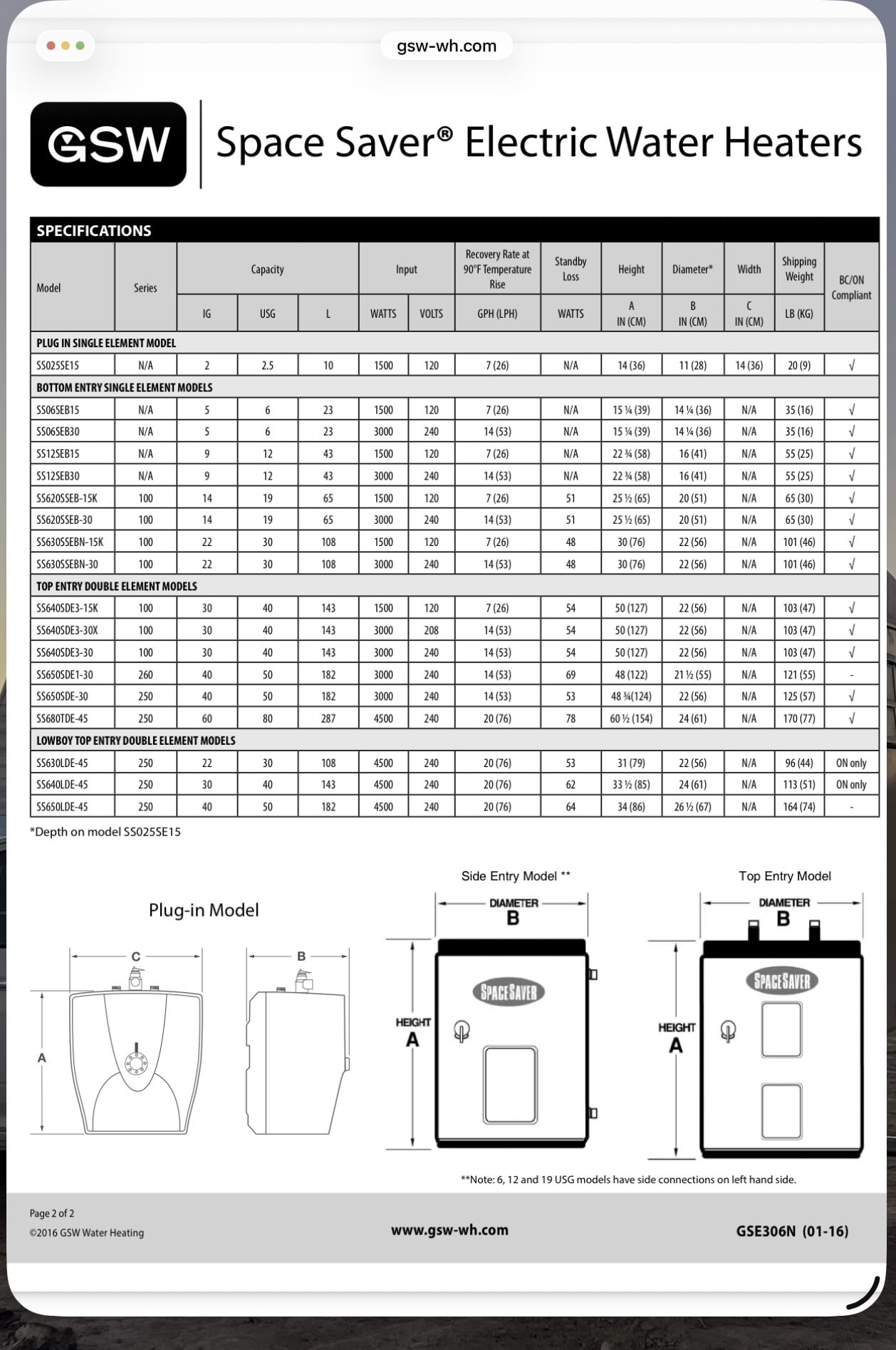
Its a GSW SS12SEB15.
The element port is about 2" above the lower cold port.
There is a drain maybe 2" below the cold port.
Potentially a 3-port buffer if I utilize the lower side main port for my Load returns and the drain port as the return to the boiler. I could tee off a new drain port from that boiler return. I should pull the drain valve off to see if that's a 3/4" or 1/2" port.
30+ yrs in telecom outside plant.
Currently in building maintenance.0 -
If you can exchange that tank, the dual element version would be a lot simpler. That gives you two 1" NPT ports at the right location, what I used for my DIY indirect tank.
Otherwise I would connect to the drain and the T&P port. No dip tubes or thermosyphon valves to deal with.
0 -
it looks like the model number that ends in 30,
SS12EB30, is the 12 gallon dual element version. That would be a better option as @Kaos mentioned.
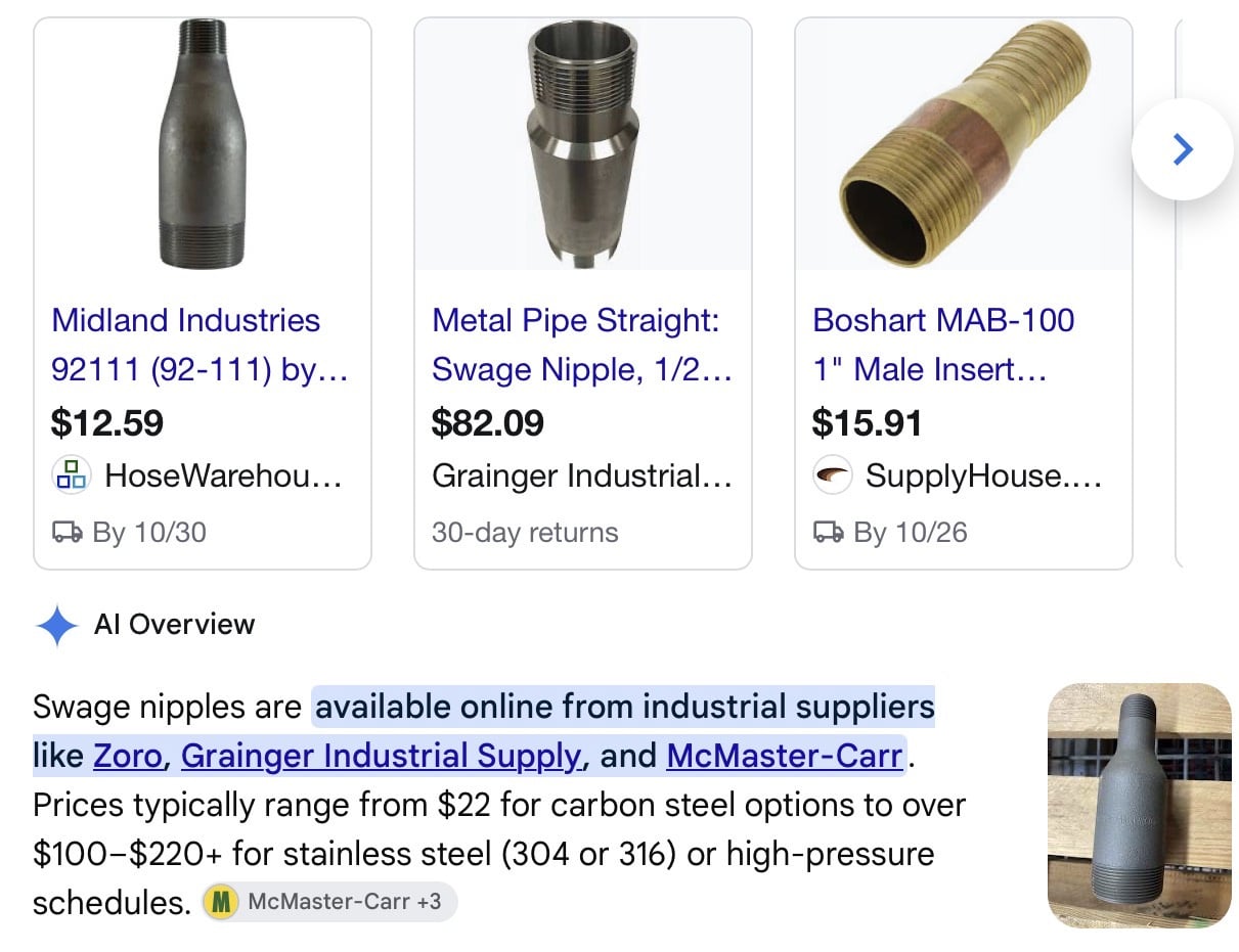
Also I see a lot of options for 1x swage nipples online
 Bob "hot rod" Rohr
trainer for Caleffi NA
Living the hydronic dream0 -
Cant return it.
I measured things instead of eyeballing.
Top of unit - 23"
Upper main port - 16.75" with a curved "J" pipe that bends upward
T&P - 16.75" (looks higher when looking down on it on the floor lol)
Element - 7"
Lower main port - 3.5" with a curved "J" pipe bent downward
Drain - 3"
——So.. how about:
Upper Main - out to loads
T&P - to Boiler supply
Element hole - Sensor well
Lower Main - to Boiler return
Drain - in from Loads (plus a drain point)
I did kinda want to do a 2-pipe, but maybe a 4-pipe would help with my narrow buffer ports ?
30+ yrs in telecom outside plant.
Currently in building maintenance.0 -
4 port is worse in this case as you have push all your flow through the 3/4" ports and dip tubes on the tank.
Stick with 2 port, this way only the difference between secondary and primary flow rate has to go through the tank. Generally, if a couple of zones are calling, this won't be much, so it port size won't matter much.
I would still go with the T&P and drain port with an adapter to bring it up to size as quickly as possible. This avoids the extra restriction of those dip tubes.
Also find a spot for an auto air vent on the top, maybe the anode port. It will make getting the air out of the system much easier.
0 -
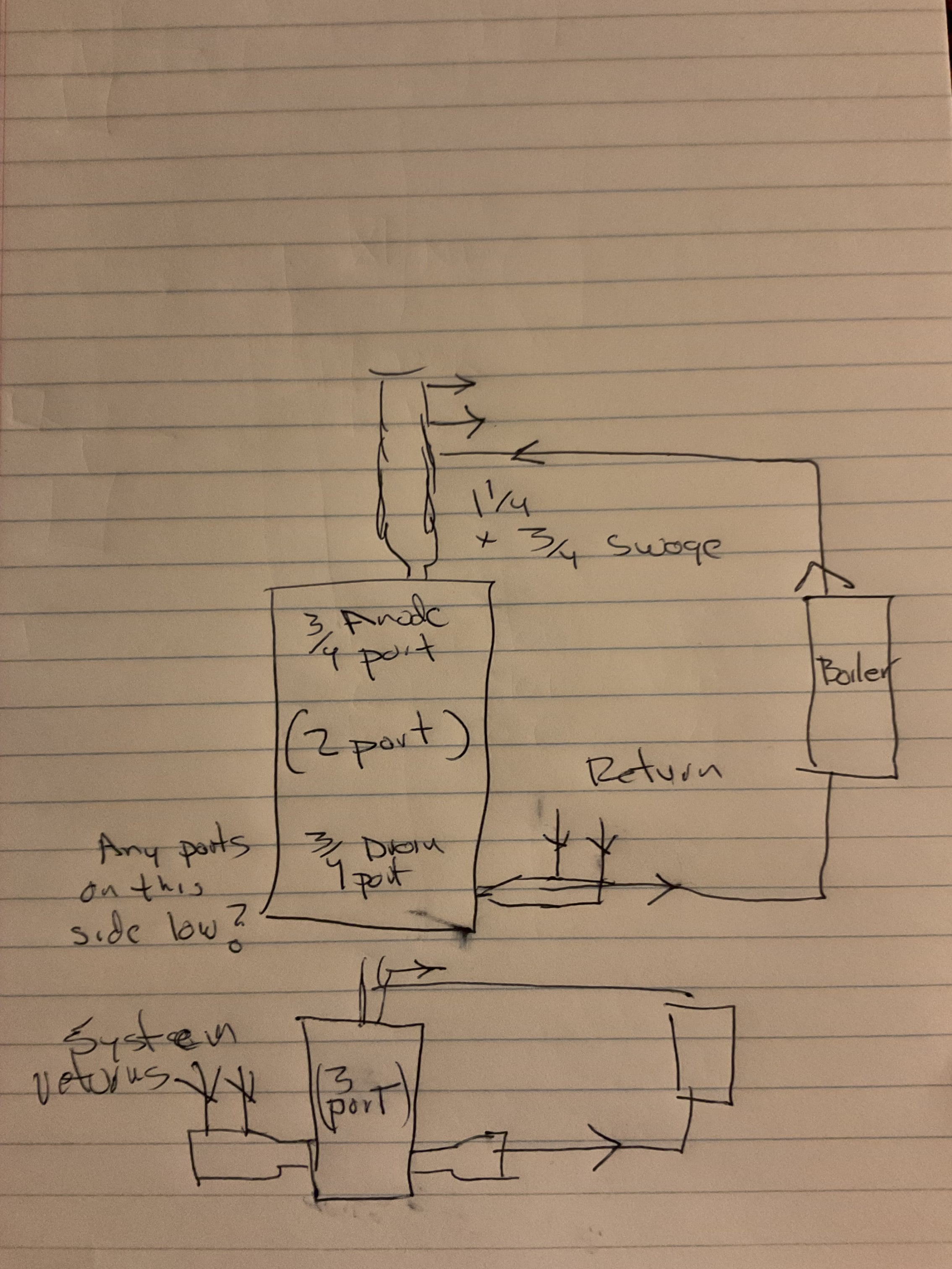
if you have a good airpurger in the piping, use the anode port for one connection.
If you have 2 ports at the bottom you can do a 3 pipe.
Here is a 2 and 3.
Do you have access to e bay, Amazon, Grainger, Amazon? Find 3/4 x 1-1/5 swage nipple. It is a nice flow friendly transition fitting
 Bob "hot rod" Rohr
trainer for Caleffi NA
Living the hydronic dream0 -
Regrets, I have a few.. (Sinatra)
The T&P and Drain ports stick out at different angles. To use them as a 2-port, it would be super ugly. I would have to bring the pipes way out away from the wall, or the tank further away from wall, or have both ports sticking out the wrong side (gas line, neutralizer and drain on this side, plus my 60gal water heater is right there).
Back to square one.. At most, I would have just over 5gpm flowing thru those pex lined 3/4" H/C ports. Would the restriction in the ports "J" tubes be enough to f-up the separation of pri/sec ?
I was going to use 1.5" tees and nipples with a 1.5 x 3/4 coupler on the ports.
When I struck out locally sourcing those swage nipples, and considering we're already hitting freezing mark here at night, I just switched to couplers plan. Had I ordered swage on amazon or such at the time, they'd probably be here by now. Regrets..
On a happy note, I've found that 3:! of deionized and my well water fits the bill for boiler specs for hardness/ph/etc . $7/gal for the deionized is tolerable. System vol is maybe 20 gal ? (1300 ft of 1/2" pex and a 12g buffer).
On a side note, I read that deionized when exposed to air becomes more acidic and the ph level isnt necessarily neutral in the container . The brand I have didnt lower the ph of my well water when mixed in and tested. I'll track that and add conditioner to the Axiom fill stn as needed.
30+ yrs in telecom outside plant.
Currently in building maintenance.0 -
the hydraulic separation is in the large pipe you are building, the tank is just a container.
When you reduce you will get a velocity increase through the smaller opening. At the flows you are talking it will not be an issue. But I rather not go through a section of 1/2 which is what those dip tube I’d may be.Can you use the top anode port, then any side port will put you in the position you need?
The anode may be under a plastic plug up top. The anode and drain ports would be my choice.
DI water is hungary water, the di process strips most everything from the water, it will be a low ph. It will buffer itself when exposed to air or once in the system. Ph will increase, it is trying to get to a neutral condition.
. But the conditioners are still a good addition to hydronic fluid, they have other important ingredient in addition to the ph buffer. The buffers may take it to a high ph, use the test strips they provide to know the condition.
Bob "hot rod" Rohr
trainer for Caleffi NA
Living the hydronic dream0 -
On top, there are two more H/C ports plus an anode port (where I was going to have vent). Would top port not mix the tank more aggressively and raise the return temp at the bottom port (and sensor in the element hole ) ?
What if I yank the side H/C oem nipples out and use regular nipples.
If I use black for the large pipe and entrance nipples ,that should be fine entering a steel tank I assume. I was going to use brass between the large pipe tees and the copper pipes.
30+ yrs in telecom outside plant.
Currently in building maintenance.0 -
Don’t worry about an air vent on the tank, the proper buffer connections allow you to use as much as the tank as possible. So the wider the connection spread the better.
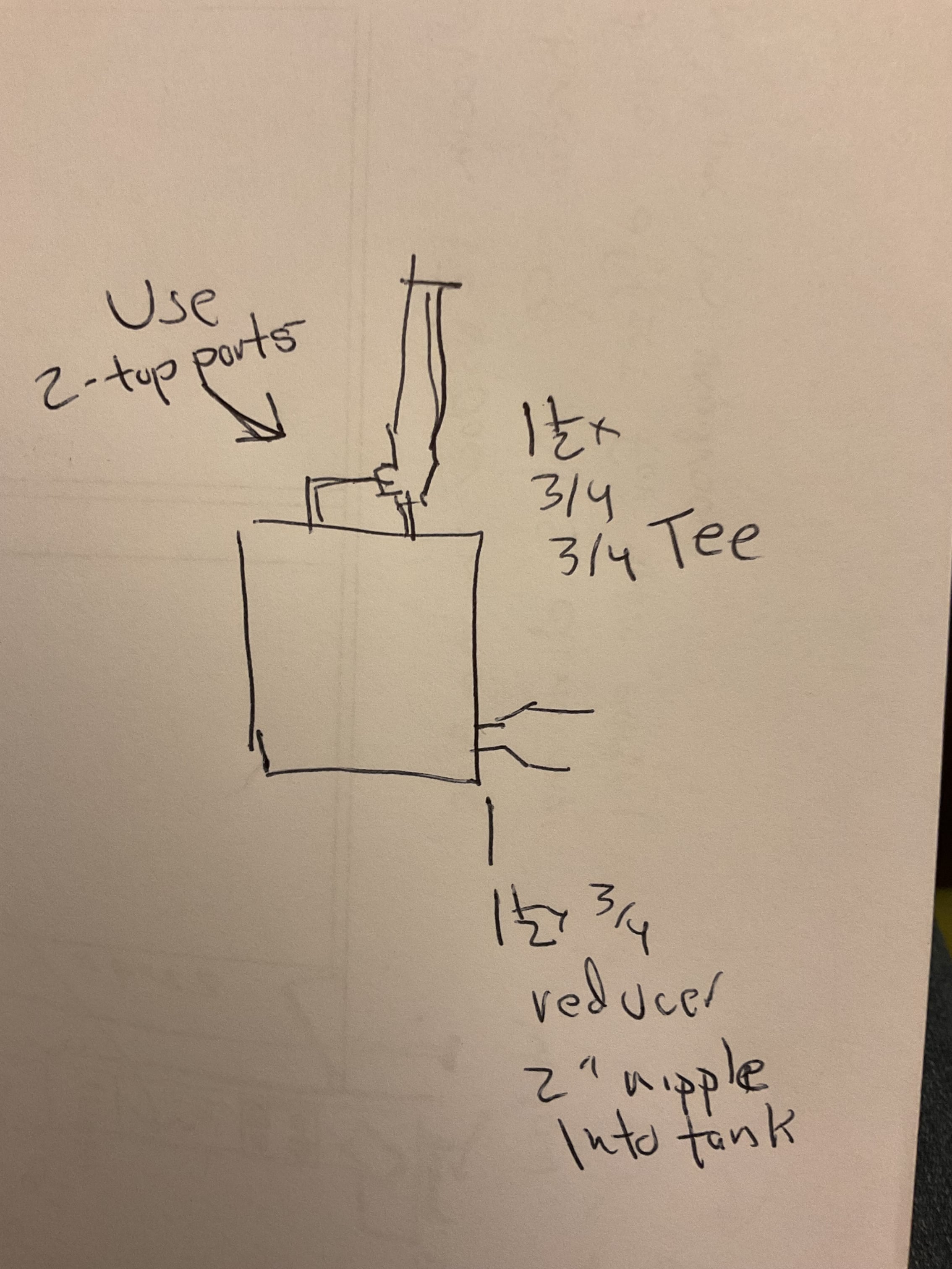
Are there two top connections and an anode rod up top?
on one install I connected the 2- 3/4 top ports together. This spreads the flow into the tank, lessens the velocity effect. 1-1/2 x 3/4 x 3/4 tee,use reducing couplings instead of bushings on the other port for a smoother flow.
 Bob "hot rod" Rohr
trainer for Caleffi NA
Living the hydronic dream0 -
Your flow rate is not that high, with a two port setup, 3/4 is more than enough. I would pull the OEM nipples (those have have anti syphon valves in it, so have to go no matter what) on the side ports, remove the dip tubes and connect to there. Nice clean install and it just looks right. You can use black pipe for all of it as is flowing passivated water, a brass nipple would make it easier to take apart if you ever need to though.
Something like 3/4 short nipple→ 1 1/2" to 3/4" reducer→manifold. If you want to go fancy, do a bit of port/polish on the reducer/nipple connection so it flows better.
With such a small tank mixing doesn't matter as the tank will mix very quickly no matter what you do when the system runs.
1 -
Ideally that element port on water heaters used a square o-ring to seal an element in.
I have use a standard NPT nipple with a few wraps of thick teflon tape and they seal.
I did weld a large washer on a 1" nipple to squash the o-ring, but it was a bit overkill.
Bob "hot rod" Rohr
trainer for Caleffi NA
Living the hydronic dream1 -
I like the idea of the bridge pipe across the 2 top ports, but how would that get assembled ?
Seems like a union might be involved ? My top ports are 8" apart.
Something like this ?
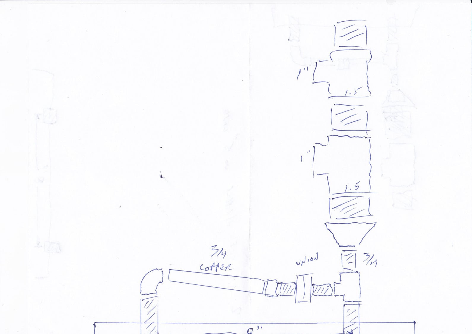
I messed up my sketch, but would the side port of a 3/4" tee be parallel with an elbow on the other port ?
Also, I can mix and match materials black/copper/brass except for the bits that need to be soldered to the copper of course (they would have to be copper or brass) ?
Edit : Or I suppose I could sweat that whole lower assembly. (no union)
30+ yrs in telecom outside plant.
Currently in building maintenance.0 -
If you use the top connections you need to remove the nipples that are in the tank, they most likely have checks in them.
Then sweat 3/4 copper to male adapters on some tube, screw it into the tank and build up from there. No need for unions if you work with sweat or press copper.Copper into the tank is fine on a hydronic system, no need for brass or dielectric unions.
If you are using threaded nippled, yes you will need a union.
Bob "hot rod" Rohr
trainer for Caleffi NA
Living the hydronic dream0 -
This is going to lay out nice in my space ! The top port assembly ends up closer to the wall and the return lines with the dirtmag and 15-55 come away from wall for a bit easier servicing.
The top ports have square drive plugs in them, but I will verify nothing else stuck in there.
I think the expansion and fill station are going to have to go into the anode port on top. Im already really close to the floor pipes on the left at the drain end.
Im going to try the sensor in the T&P port. If that doesnt work out, I can switch to a probe under foam. When the boiler is heating there should be enough mixing to not trigger the sensor too early, but once the boiler pump stops and the tank starts to stratify, the sensor should remain satisfied until the heat is nearly gone.
I appreciate the help guys.
 30+ yrs in telecom outside plant.
Currently in building maintenance.0 -
With a tank that size don't worry too much about the sensor placement. If the tank was 5' tall it would be more critical. That short tank temperature will be pretty well blended.
Are you going with copper piping or threaded? Or a blend of the two.
Copper would be clean and easy but crazy $$
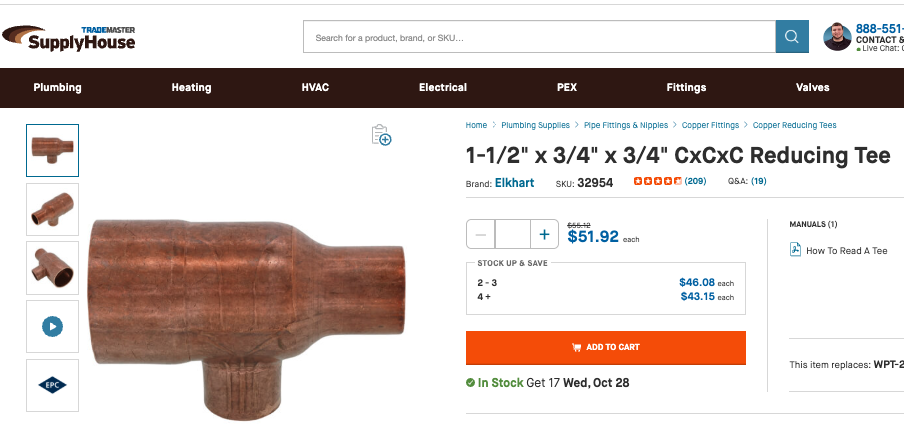
This tee would be ideal, but if you want to stack threaded fittings start 3/4 copper from the tank then bush into a threaded steel large tee.
T tee- drilled section would take a lot of fitting cot out if you go copper.
 Bob "hot rod" Rohr
trainer for Caleffi NA
Living the hydronic dream0 -
I have a converted water heater for my buffer tank and hooking the top 3/4" ports together is where pex really shines. Use 3/4"mip x 1"pex adapters and use 1" oxygen barrier pex from there on. You can get the anode port hooked in to the "header" with little added extra work. I'll admit, you're not going to flow enough for a big boiler but my smallish mod-con with in-floor radiant works fine with no flow noise.
0 -
0
-
I have the copper/brass/black parts now, but the pex thing has me wondering.
Does all the flow into the buffer from a 'fat header' have to flow out the same point of the header ? Could you do one end plus say half way up the header , both going into the buffer ? (or out of the buffer depending on what phase of cycle is happening).
Perhaps there would be too much turbulence when the boiler and load circs are both running.
30+ yrs in telecom outside plant.
Currently in building maintenance.0 -
short, fat header. You want connections close to one another, the fat header close to the tank
In a perfect world this might be a round ball. Little to no flow resistance between any connections
You would need to be far off from the best practices for it not to work at all, however
Check valves are your secondary protection against unwanted flow. I think most any circ you buy today has checks in it or in the box with it
While they are in the worse possible location, the turbulent discharge of the pump, they maybe do more good than harm
 Bob "hot rod" Rohr
trainer for Caleffi NA
Living the hydronic dream0


Categories
- All Categories
- 87.9K THE MAIN WALL
- 3.3K A-C, Heat Pumps & Refrigeration
- 60 Biomass
- 430 Carbon Monoxide Awareness
- 133 Chimneys & Flues
- 2.2K Domestic Hot Water
- 6K Gas Heating
- 124 Geothermal
- 172 Indoor-Air Quality
- 3.9K Oil Heating
- 80 Pipe Deterioration
- 1.1K Plumbing
- 6.7K Radiant Heating
- 397 Solar
- 16.1K Strictly Steam
- 3.5K Thermostats and Controls
- 56 Water Quality
- 51 Industry Classes
- 51 Job Opportunities
- 18 Recall Announcements