Shshs

Hey everyone, I’m chasing down a persistent hydraulic issue on a residential radiant setup and could use some expert eyes.
System Configuration:
Heat Source: Navien combi boiler configured with primary/secondary piping.
Circulators: Dual Grundfos UPS15-58FC wet-rotor pumps (multi-speed).
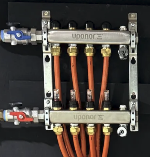
Distribution: Uponor radiant manifolds with built-in flow meters.
Controls: Tekmar 519 thermostats managing zone calls.
The Symptom:
The system exhibits a bizarre hydraulic "run-out-on-the-curve" behavior on the secondary loop. When the manifold balancing/ball valves are fully open, the Grundfos circulator appears to stall or lose its grip entirely—flow drops to near zero across the manifold flow meters, regardless of whether the pump is set to Speed 1, 2, or 3.
However, if I partially throttle a downstream ball valve to artificially introduce head pressure, the pump instantly catches, flow stabilizes on the meters, and the system circulates properly.
What's Been Tried:
My plumber has already swapped in three brand-new pumps trying to solve this, and the exact same behavior happens on all of them. Changing pump speeds (1, 2, 3) has zero effect on the stall behavior when the valves are wide open; the pump acts identical across all speeds.
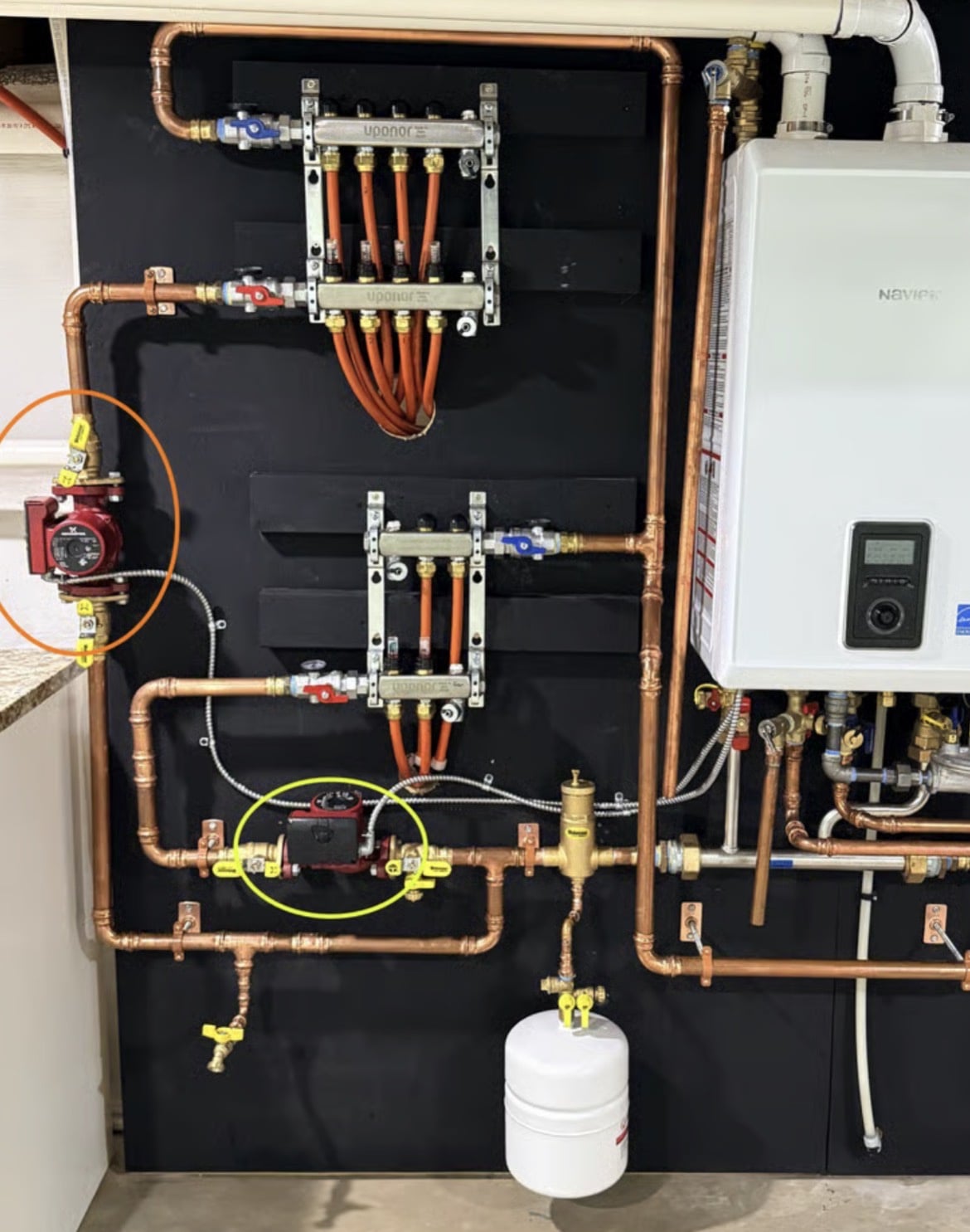
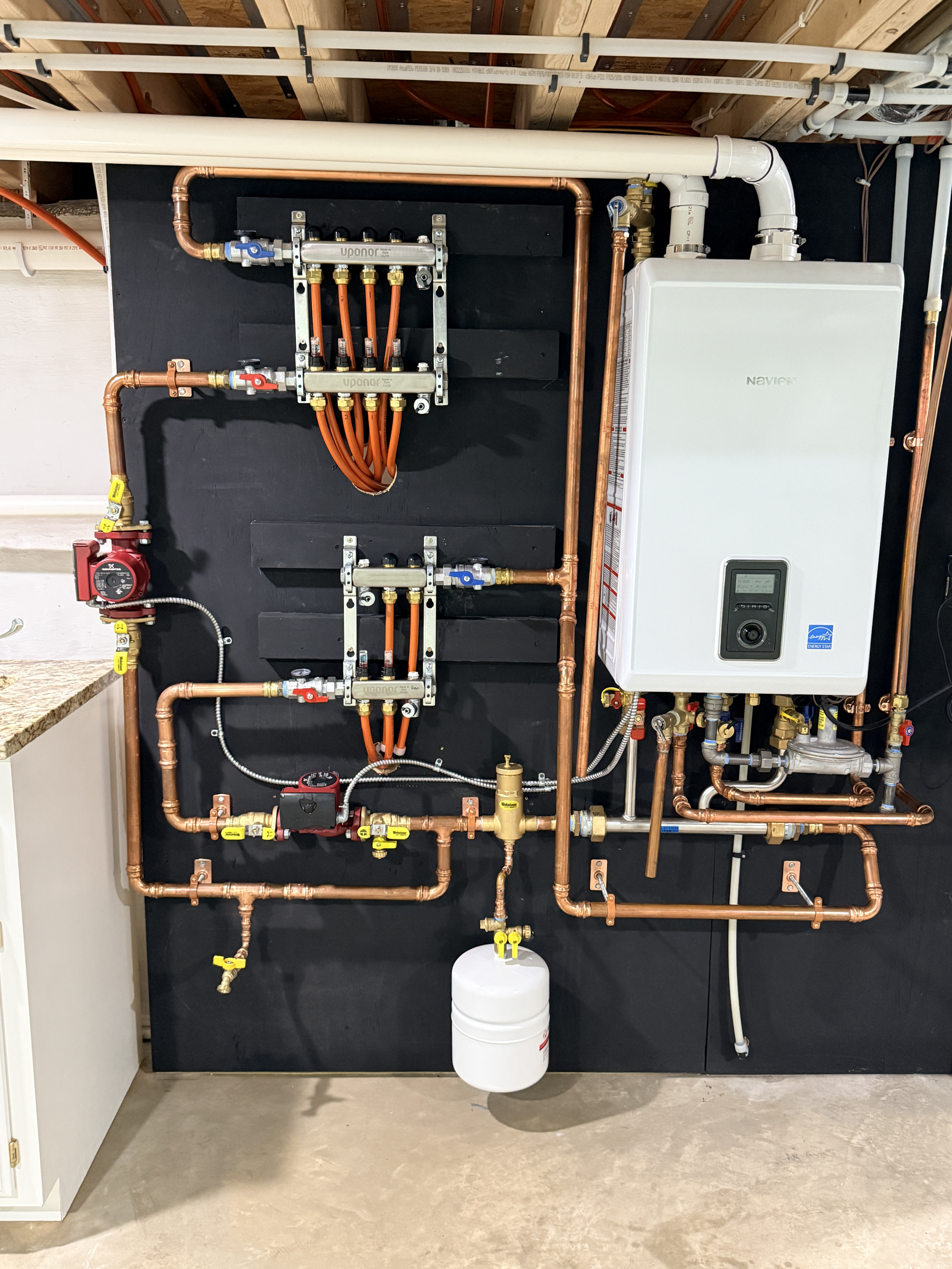
Here is a photo of the mechanical board layout:
(Attach the photo here)
Has anyone run into a similar scenario where a Grundfos circulator on a low-resistance loop requires added downstream head resistance just to maintain its vector flow? Any insights on whether this points to an air-binding quirk, a primary-secondary hydraulic decoupling issue, or differential pressure across the circuit would be greatly appreciated.
Comments
-
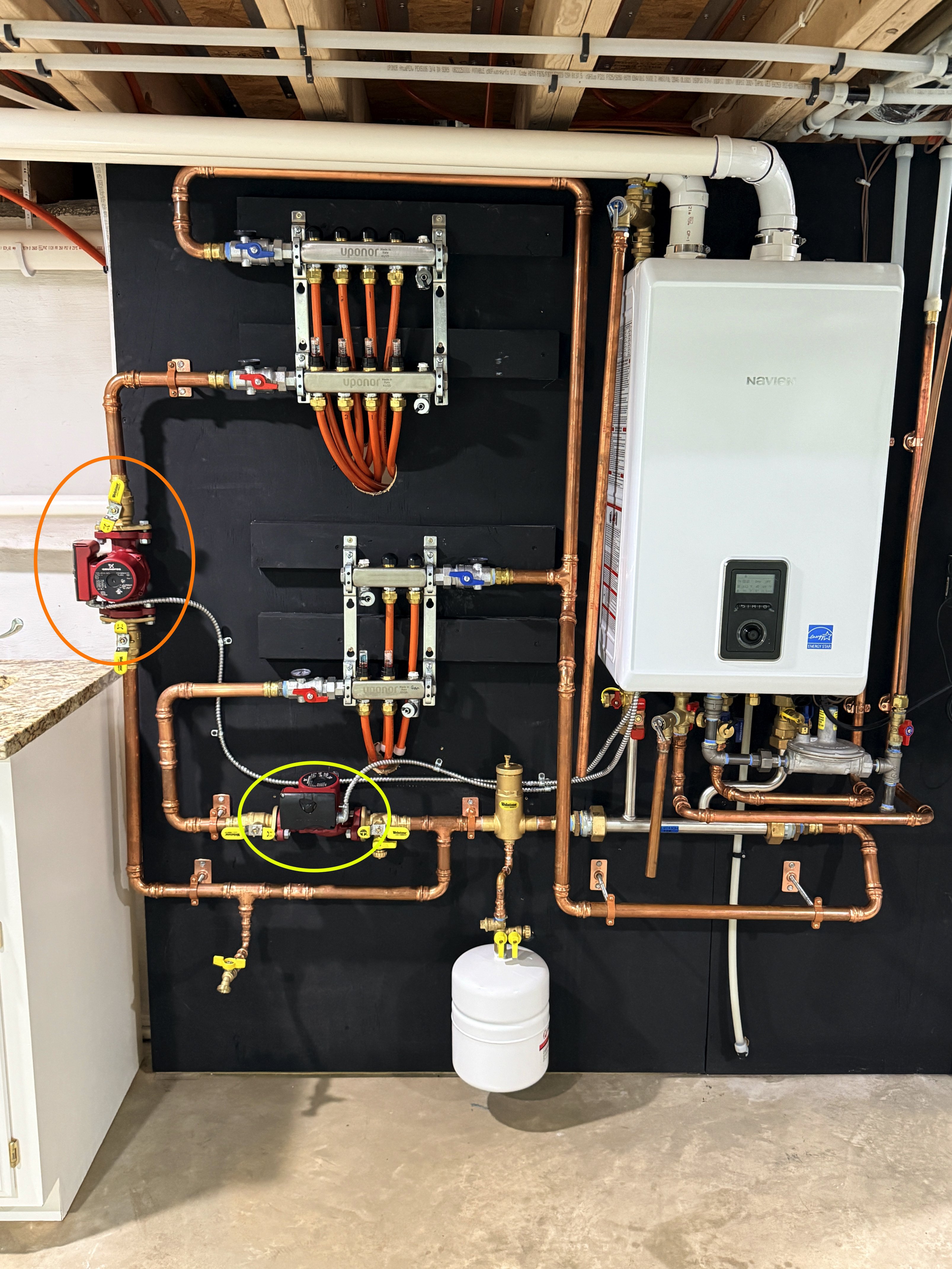
Does this happen on both zone pumps? Yellow or orange of both?
Edward Young Retired
After you make that expensive repair and you still have the same problem, What will you check next?
0 -
There is a reference to a pump failing to start under some conditions. it refers to the bearings not having sufficient water pressure to lubricate the water lubricated bearings.
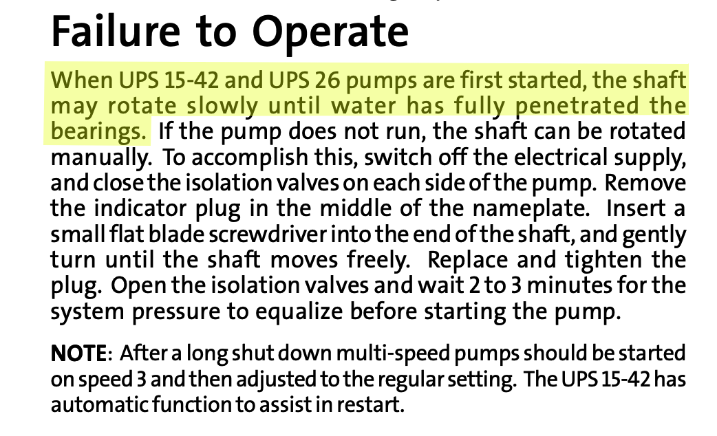
Perhaps this is the reason for the slow operation without the artificial head or pressure resistance you cause with the partially closed ball valve. Seems weird that you are having the problem you describe, but I can't think of any other explanation.
Edward Young Retired
After you make that expensive repair and you still have the same problem, What will you check next?
0 -
Hello Ed, thanks for the response.
It only happens to the pump you circled in orange. The yellow one works normally. I’ve had three local plumbers, HVAC, and hydronic people over, and none of them have an explanation—including the guy who installed the system this spring and Ferguson (who engineered/designed it).
Regarding the 'failure to operate' scenario: I can leave that pump running for 12 hours straight without an issue if the valve is throttled. But the second I fully open the ball valve, it immediately stops moving water. Because it moves liquid just fine under restriction, I have to assume the impeller and motor are completely fine. It's strictly acting up when the system resistance drops away.
0 -
checks working in both pumps?
Flowing the correct direction?
System purged adequately?
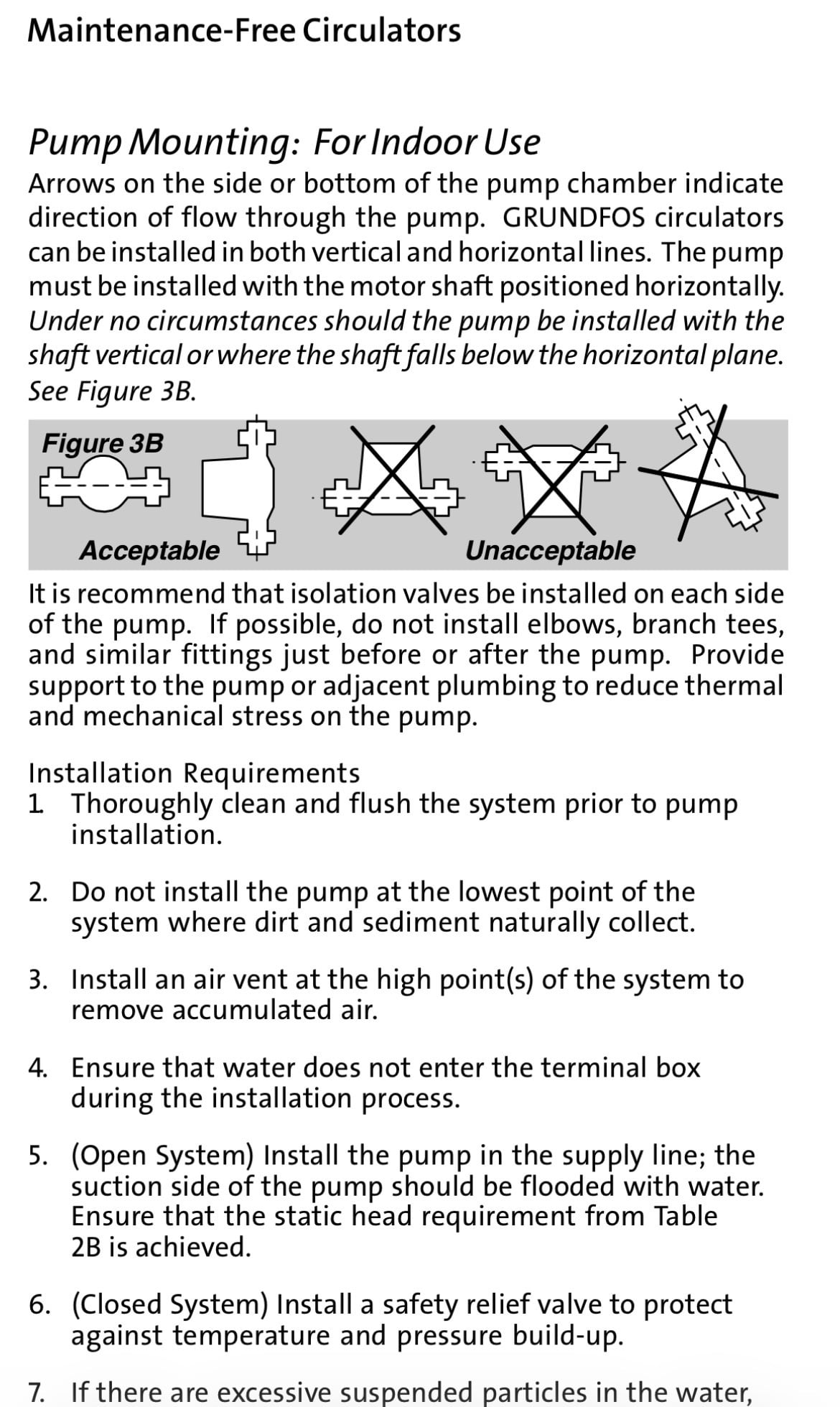
Lower pump should be rotated so motor is horizontal
With a 3-31/2 gpm flow requirement maybe a single pump and two zone valves with a delta p circ is a better option. Even on speed 1 you are probably over pumping.
But it should circulate on any speed setting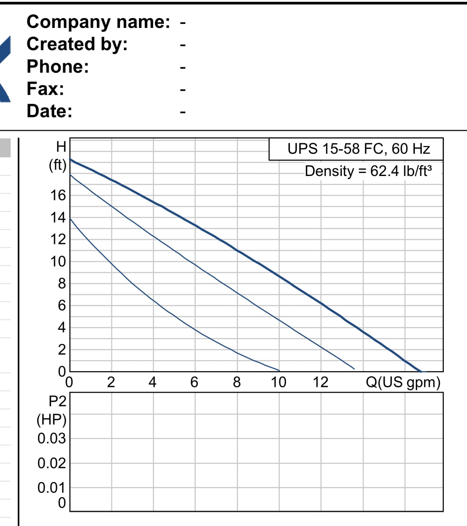 Bob "hot rod" Rohr
trainer for Caleffi NA
Living the hydronic dream0 -
-
Thanks for taking the time to respond and help Hot Rod! I appreciate it very much! To give a bit more background: I actually paid to have this system professionally installed about 6 months ago. It ran for a few days before it froze up and stopped working completely. I called the installer back, and he finally came out to fix it just last week—and it still isn't working 100% the way it should. He can't explain why this is happening, so I'm having to take the initiative to figure out what's going on and how to fix it myself.
While reading through all the instruction booklets that came with the equipment, I agree that the garage pump orientation is wrong, and I'm going to make him fix that. However, that garage loop actually works fine.
Before I talk to him again, I am trying to get a solid understanding of what is causing the house loop to only work when the valve is partially cracked. To test this, I went into the Navien boiler settings, turned on test mode to run the 4-loop zone pump, and shut off the valves to the garage and the boiler loop. Even isolated like that, it still has to be throttled down to move water.
For more context on the layout that I probably should have mentioned initially: the 4 loops add up to just shy of 1,200 feet total, the boiler is down in the basement, and the radiant tubing is run up in the wood floor joists above the system.
0 -
As for the checks, my plumber initially thought a stuck check valve might be the culprit, so he pulled the original pump and found it didn't even have one installed. He temporarily swapped in a smaller-head spare (I believe a 15-55 model) that had a check valve, but experienced the exact same issue. He then warranty-replaced the original pump, and I personally saw the check valve built into that new replacement.
0 -
Which way is the flow through that pump? If the flow is downward, it may be cavitating, as @Steamhead suggested. If it is, it won't pump much (it will pump a little) and closing the outlet valve partly will allow the impellor to fill and work.
Br. Jamie, osb
Building superintendent/caretaker, 7200 sq. ft. historic house museum with dependencies in New England0 -
turn the isolation valves off on the small loop and try it
Also bleed the upper manifold at the bleeder screw as it runs, and maintain 12-15 psi as you do
Bob "hot rod" Rohr
trainer for Caleffi NA
Living the hydronic dream 1
1 -
Hi Jami and Hot rod, I do agree that the pump is too powerful for the amount of resistance it sees in my pipes. I am going to contact the installer about getting the pump switched to one with a variable ECM so it can go low enough to have no cavitation. Thanks much for the help, especially the graph—it appears my current pump pushes 8–12 GPM, and my loops only need 3–4 GPM total.
0 -
What Happens in Your House Loops
1. Designed for Resistance: Pumps are engineered to work against a certain amount of natural friction and restriction (head pressure) from piping, valves, and fittings. That resistance acts like a brake, keeping the pump operating safely in the middle of its curve where it maintains a steady, controlled flow.
2. The "Wide Open" Trap: Because your house loops have low natural resistance and wide-open parallel paths, there isn't enough friction to act as that brake.
3. Sliding to the Bottom Right: With no resistance holding it back, the pump's operating point slides all the way down and out to the extreme bottom-right edge of its curve (hence, "running out on the curve").
When it gets pushed out there, two bad things happen simultaneously:
Maxed-Out Volume: It tries to shove way too much water (~8–10 GPM) through pipes that can only handle a fraction of that.
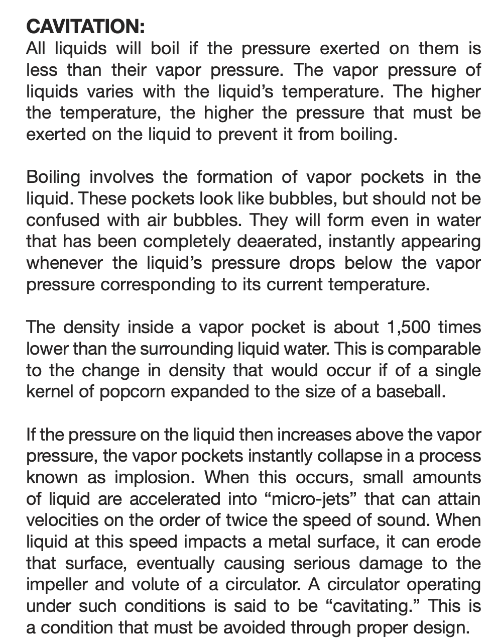
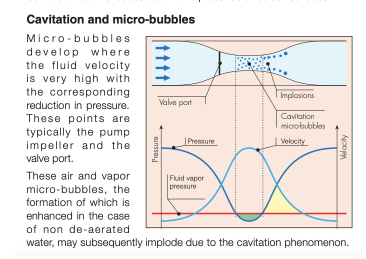
Zero Backpressure & Cavitation: The pressure at the impeller drops so low that the water literally vaporizes into microscopic vacuum bubbles, causing that "gravel in a blender" noise and stalling the flow.
When you partially close your ball valve, you are manually forcing artificial resistance back into the system. That "brake" pushes the pump's operating point back up and to the left, right into its happy, quiet zone. A variable-speed pump does that automatically by electronic magic instead of needing a closed valve.
 1
1 -
Does it only happen when the pump circled in yellow operate at the same time as the other pump is running?
There is no hydrolic separation between these two pumps??
Why is one pump mounted vertically?
0 -
I can shut the valves off to the lower pump to make the system like a “1 zone system” and it still occurs. There is nothing wrong with a pump being positioned vertically?
0 -
The arrow on the pump body is pointing towards the manifold?
All the manifold valves open?
 Bob "hot rod" Rohr
trainer for Caleffi NA
Living the hydronic dream0 -
Yes they are flowing proper way. And yes the one pump is wrong, going to get it fixed.
0 -
Are the valves embedded under the flowmeters open fully ? Perhaps they need to be for your design output, but closing them a smidge (or more) might buy the head you seem to need ?
30+ yrs in telecom outside plant.
Currently in building maintenance.0 -
I tried messing with them didn’t seem to fix I truly think the pump is wayyyy to big for the amount of pipe.
0 -
I would stary with a good power purge. Without a fill valve you will need a hose of pump to get a good flow to shove air. one loop at a time. Purge right on the manifold valves to assure you are going through thr loops.
The plastic caps on the upper, return manifolds are shut off valves. Are the caps loose, the open position is with a loose or removed cap.
Or take a pump out on the four allen screws 4mm or 5/32 allen, and assure it spins when powered/
 Bob "hot rod" Rohr
trainer for Caleffi NA
Living the hydronic dream 2
2 -
BTW where is your water MU for the heating system? I am not seeing that or a PRV to feed city water?
I agree with @Steamhead that it is cavitating. Too large of a pump. I think your way over pumping
I would also remove the expansion tank and/or isolate it and check the air charge. Iffy expansion tanks can cause strange issues
0 -
no fill valve because system is full of glycol. Had a pump, pump glycol through for about 45 minutes each zone I’m very confident no air in system. Yes the caps are loose would fall off if you touched them.
0 -
Air in the impeller can be burped by loosening the flange bolts.
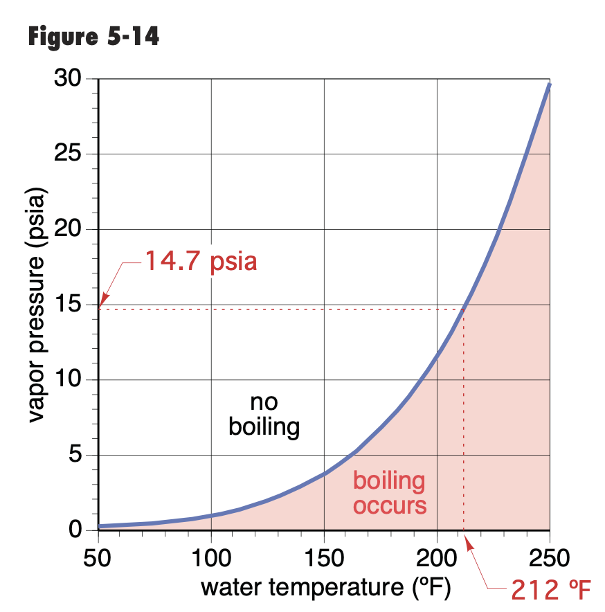
It's tough to cavitate those small circs, To get below vapor pressure you need either very low pressure or vacuum conditions or very high temperature. Or both.
Wood boiler pumps often cavitate, low pressure and 200° plus temperatures.
You can cavitate in a fitting however, by chocking it way down. You generally hear a rice krispy sound when you get a cavitation condition. Chocking down the valve should make it worse, not better?
If the pump body get very hot, 10 or so above the glycol in the volute, the motor heat can eventually boil the fluid. An air locked pump, or stuck impeller for example.
A glycol mix needs to get above 212 to boil, plus the pressure condition raising the boiling point. Maybe 230or more. Which would be very hot pump body!
 Bob "hot rod" Rohr
trainer for Caleffi NA
Living the hydronic dream0 -
That appears to be 1/2" pex. What are the loop lengths for 1 thru 4 circuits? What is the flow indicators set at?
There might be air trapped somewhere in the sys. I can see high spots in your photo, maybe needs an air vent or a high pressure purge, which you say you've done.
Those 2 circs have check valves in the volute? Did you bleed air out of the manifolds?
You can get a pump with a reverse flange.
What is the solvent that the PVC venting is put together with, looks black. ABS??? Should be purple primer with clear PVC or PVC & ABS green cement.
0 -
1- 12 psi is typical, but if it is air free it will circulate at 0 psi.
Could the loops be connected incorrectly. Did they confirm supply and return on every loop?
Another loop by loop air purge would be the first simple step. Pull the pump, check rotation.
What do the flow indicators show? Typically .5 gpm or more per loop..
Bob "hot rod" Rohr
trainer for Caleffi NA
Living the hydronic dream0 -
If the circ. Is in the basement but tubing goes to first or second floor, if the static pressure isn’t high enough wouldn’t the pump have similar issues?
0 -
@Brent H. , good point. Where is the cold water feed ( I think I found it)? Sys pressure should be about 15 psi, I would think.
With a glycol sys I use an Axiom fill tank which circumvents a reduced press backflow preventer. It maintains sys pressure that matches Extank bladder air pressure. Low sys pressure can lead to cavitation.
0 -
Your pump is fine. Even if you wanted to push 1 gpm per loop at 300' of 40% glycol it looks like this, 15.3' head.
so 4 loops= 4 gpm at 1 gpm per loop 15'. Speed 3 gets you there.
Generally .5- .65 gpm per loop is design for 1/2 pex.
Hopefully the loops are 300' or less? And glycol 40% or less?
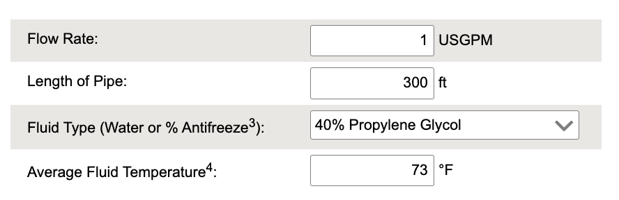
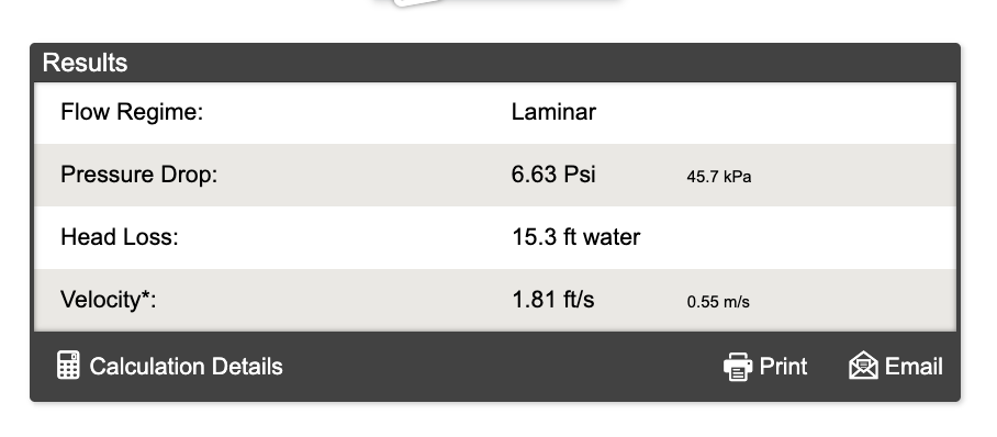
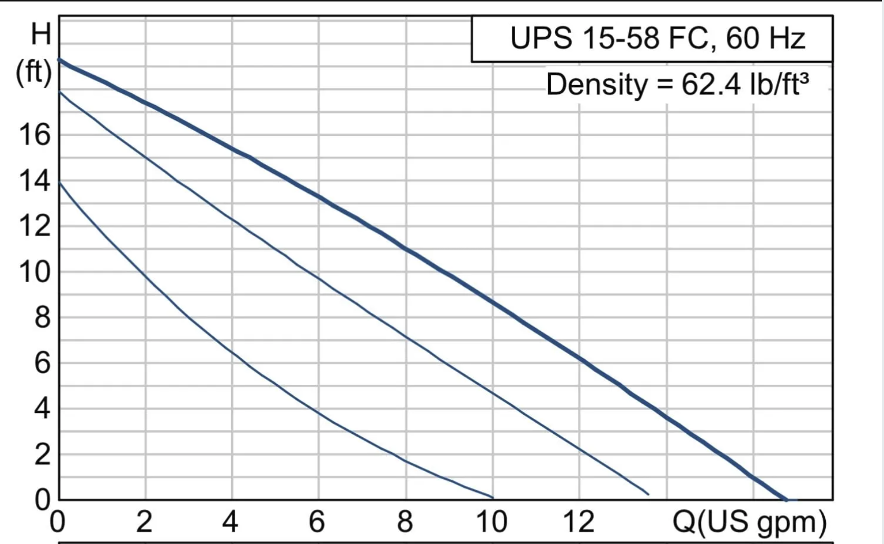
A more realistic .65 gpm per loop, see below, 2.6 gpm for that manifold, = 6.25' Speed 1 covers that nicely.
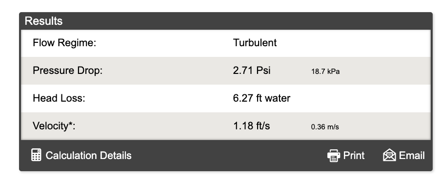
All 6 loops flowing @ .65 gpm each= 3.9 gpm @ 6.25', still within that 15-58 reach.
As glycol warms above the 73° I used, it flows easier, so numbers get better, pump-wise.
Bob "hot rod" Rohr
trainer for Caleffi NA
Living the hydronic dream0 -
The Navien combi boiler displays system pressure on the home screen, and will change to a red screen in error mode if pressure drops too low. However, I still suspect low pressure in this situation, especially without a system feed. The pressure will drop in a new system as the oxygen is gradually purged out over many heating cycles. Also in a 2-story application, I would think you would want your system pressure to match your expansion tank pressure. If it's too low, sometimes a circulator MIGHT work simply by creating negative pressure on the suction side of the circulator. But this is when you open up a can of worms. You can suck air into the system through your air separator, etc. Make sure pressure is up around 12-15 psi, and let us know how this shakes out. We've got several systems out there very similar, so we're interested in your outcome.
0 -
To confirm… the expansion tank internal air pressure, when disconnected from the system, must be set at the desired cold static pressure of the entire system. It cannot be set correctly while the tank is connected to the system.
It should be around 12 to 15 psig for a typical two story residential application.
And yes indeed. Depending on the piping configuration and the location of the pump in relation to the expansion tank, it is quite possible for a pump under high flow conditions to drop the inlet pressure below the required net positive suction head, cavitate, and stop pumping. It's rather astonishing — and a credit to the pump designers — that this problem doesn't happen more often…
Br. Jamie, osb
Building superintendent/caretaker, 7200 sq. ft. historic house museum with dependencies in New England0 -
The Navien has a internal feed valve for system pressure, at least they use to . A second feed is recomended for a better air purge ..
There was an error rendering this rich post.
0 -
If 4x 300' loops of pex is too small for a 15-58 then every radiant job in my area should be cavitating. I think something else is the cause personally. 3 local plumbers and the sales people and not one of them even noticed the other pump is installed wrong? Whats the pressure on that expansion tank? almost looks like a dhw version. I would be investigating if a check valve maybe came out of a pump somewhere because its acting exactly like a stuck check, I know they swapped and supposedly added one. Where are they checking static pressure? whats the required static pressure for this job? typically i like to see 15psi but taller buildings may need more.
 3
3 -
Depends entirely on the relationship of the pump to the expansion tank. If the expansion tank is in reasonable proximity to the pump, and there are no big losses in between, there won't be a problem. On the other hand if the constant pressure is on the outlet side… you can get into problems. It's purely a matter of what is the actual absolute pressure at the inlet eye of the pump.
Br. Jamie, osb
Building superintendent/caretaker, 7200 sq. ft. historic house museum with dependencies in New England0 -
With the manifold near the boiler I assume it is one level home? Whatever the highest point above the boiler gauge X .433 is how much pressure you would have without adding pressure. That the pressure a columne of water exerts.
Many of the mod cons have pressure switches, mine needs 8 psi or it will not fire. 10- 12 psi fill is a good number to shoot for. It will go up some as it heats.
Grundfos UP series cics do not need much pressure to avoid cavitation at 140° you want 1.8 psi. You may only be running 120° or less for radiant?
As the chart indicates, higher temperature= higher inlet pressure required.
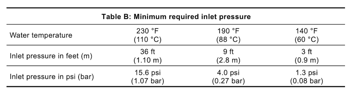 Bob "hot rod" Rohr
trainer for Caleffi NA
Living the hydronic dream0 -
Wow guys so many response so much information it is gonna take me a while to get through understanding all of that. A few things i can answer right here right now. The expansion tank came ore charged 12 psi, the system is set at 12.5 psi cold, jumps to about 22 psi warm, the boiler is on a graph for heating temp, hottest water is 120 degrees and lowest is around 85 degrees. The 4 house loops are real close to 300 ft each but not exact 320 ft, 300ft and two at around 270ft.
0 -
there is no auto fill or auto feed set up on this system is that bad?
0 -
the loops all flow around .7-.9gpm on the manifold gauges. The loops are all connected correctly, I know this cause when I watched them fill, they did 1 loop at a time.
0 -
you do not want a fill water system if it is glycol
One of these is an option.
On a small system like that, and the boiler has low pressure protection, its a big spend however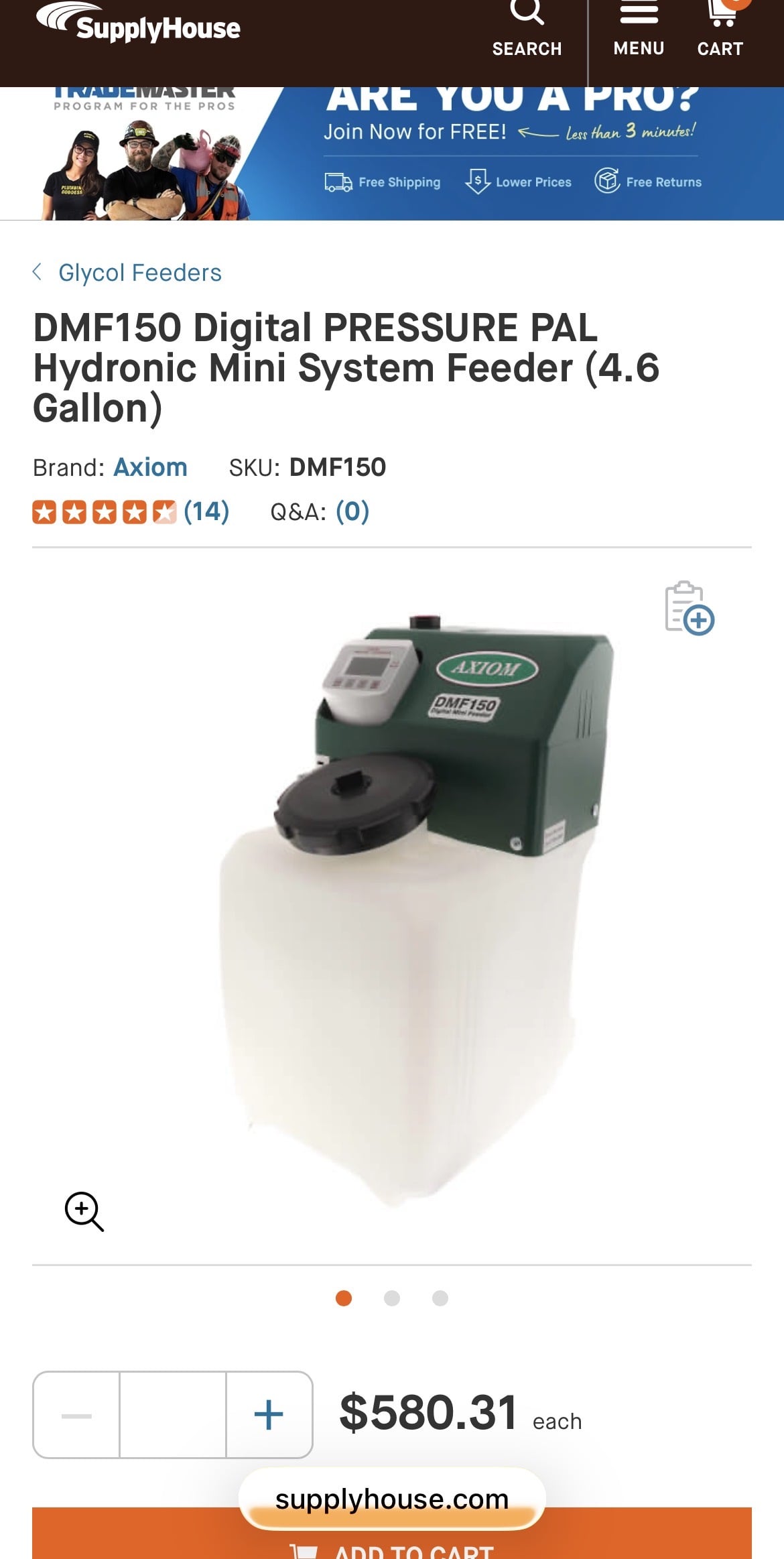 Bob "hot rod" Rohr
trainer for Caleffi NA
Living the hydronic dream0 -
And yes indeed. Depending on the piping configuration and the location of the pump in relation to the expansion tank, it is quite possible for a pump under high flow conditions to drop the inlet pressure below the required net positive suction head, cavitate, and stop pumping. It's rather astonishing — and a credit to the pump designers — that this problem doesn't happen more often…If something like Jamie says here was to happen how would you even go about testing that theory?
0 -
from what I see in this pic you are pumping away from the expansion tank. If you have 12 psi on the system, I don’t see how it could be cavitation
An air locked pump maybe, how hot does it get?
 Bob "hot rod" Rohr
trainer for Caleffi NA
Living the hydronic dream0 -
Even though yall say the pump is fine. Would putting variable speed pumps on be a good idea?
0








Categories
- All Categories
- 87.8K THE MAIN WALL
- 3.3K A-C, Heat Pumps & Refrigeration
- 60 Biomass
- 430 Carbon Monoxide Awareness
- 133 Chimneys & Flues
- 2.2K Domestic Hot Water
- 6K Gas Heating
- 124 Geothermal
- 170 Indoor-Air Quality
- 3.9K Oil Heating
- 79 Pipe Deterioration
- 1.1K Plumbing
- 6.7K Radiant Heating
- 397 Solar
- 16.1K Strictly Steam
- 3.5K Thermostats and Controls
- 56 Water Quality
- 51 Industry Classes
- 51 Job Opportunities
- 18 Recall Announcements