NTI TRX150 Wiring Help Needed

I Just installed an NTI TRX150 that has a 2 zone controller built in. It is set up with one circulation pump which goes to a manifold with 2 Honeywell V8043F zone valves with the 5 screw terminals (no leads). It is wired as shown in the NTI instruction manual (I think). One lead from the 24 V transformer (load contact) is connected to zone 1 contact 1 in the Line Voltage Junction Block on the boiler and the other lead goes to TH/TR on the zone valve; then wire goes from zone 1 contact 2 from boiler to the TR contact on the zone valve. Only 2 wires are connected to the Honeywell zone valve. The thermostat wires are connected to Zone 1 TT1 on the boiler's Low Voltage Wiring Block. It seems to work but when the thermostat is not calling for heat I am measuring 13 volts from the 2 leads being used on the zone valve; I am measuring 27 volts on the zone valve when there is a call for heat.
For those in the community with experience on NTI TRX's - do I have it wired correctly and are these voltage measurements ok? Thanks in advance for the help.
Comments
-
How about posting some pics and a diagram of how you wired it?
You cannot connect a 24v thermostat directly to the boiler.
Bob Boan
You can choose to do what you want, but you cannot choose the consequences.0 -
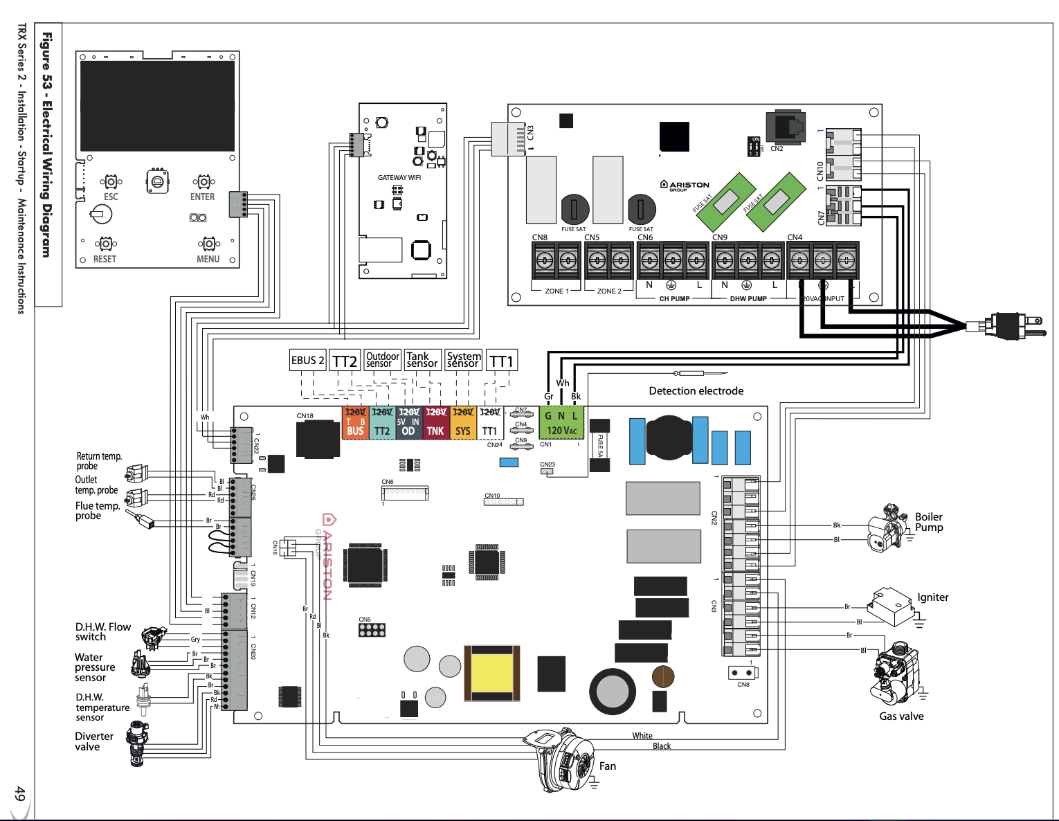
If this is the wiring in your TRX manual? You can hook two thermostats directly to the boiler, TT1 and TT2 and that enables two outputs up top Zone 1 Zone 2. Those look to be dry contacts so you need to supply 24V. If you are running zone valves.
If you are using 24V zone valves a separate relay box would be your best option.
Thermostats wire to the relay box, the relay box powers zone valves, the relay box connects to TT1 to call the boiler and pump on
But it depends on your piping, how many pumps, is it primary secondary piping?
 Bob "hot rod" Rohr
trainer for Caleffi NA
Living the hydronic dream0 -
Looking at the Manuals, NTI TRX150 and Honeywell V8043F zone valves, this is what I get out of your situation.
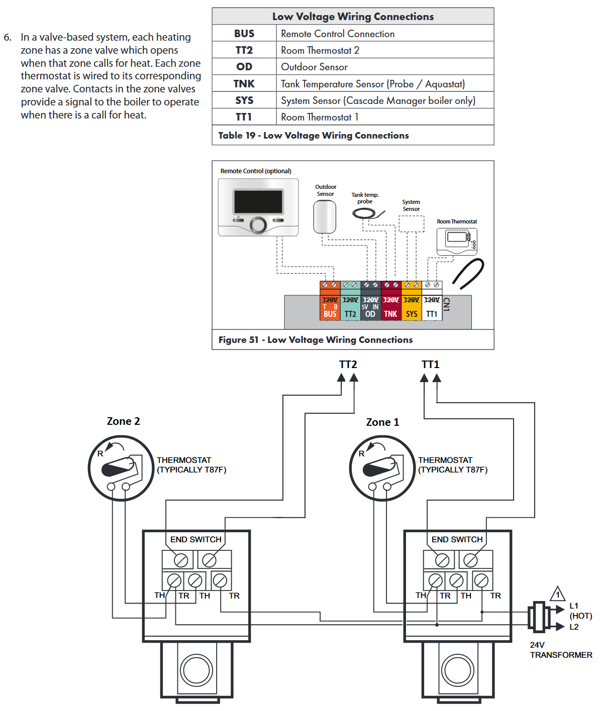
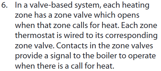
The NTI TRX150 manual (IMO) is super confusing, it shows an illustration of one thing then in text (#6 below) it explains how it should be, which is different from the illustration.
The way it should be; The added external 24 VAC transformer powers the two thermostat circuits, which includes the zone valve's motor. When a thermostat calls for heat it energizes the zone valve's motor for that zone, this opens the zone valve's valve. Once the zone valve is fully opens it closes its End Switch which activates TT1 and/or TT2 of the boiler's low voltage control, activating the boiler.
BTW the End Switch circuit has no electrical connection to the thermostat / zone valve motor circuit, they are isolated from each other.
 National - U.S. Gas Boiler 45+ Years Old
Steam 300 SQ. FT. - EDR 347
One Pipe System
 2
2 -
To explain " I am measuring 13 volts " I suspect you have the motors of the two Zone Valves effectively wired in series (which is wrong). So when both sets of contacts of the Line Voltage Junction Block are open the voltage divides by 2, for 13 VAC across each zone valve motor. If that is so the bad thing is if both zones are active at the same time it may short out the transformer, causing the transformer to fail.
The thing is you want to confirm the zone valve has actually opened so the water can flow before firing the boiler and energizing the circulator. The confirmation is the Zone valve's End Switch closing. The Zone valve's End Switch closing controls the boiler. (See the wiring diagram in my previous post)
So:
When wired as shown below you should never see 13 volts, just 27 Volts (24 VAC nominal) or 0 (Zero) Volts across a zone valve's motor, just On or Off, not half On (13 volts). And not 0 (Zero) Volts because closing both sets of contacts shorted out the transformer. In any functional or idle state the transformer should always have 24 VAC nominal at its output terminals or wires.
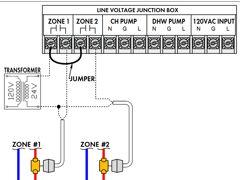
Anyways, in this wiring illustration (which is electrically correct for what it is intended to do) it provides no confirmation that the zone valve has opened, I would not do it this way, even if wired as shown here:
 National - U.S. Gas Boiler 45+ Years Old
Steam 300 SQ. FT. - EDR 347
One Pipe System0 -
Well I tried to draw this circuit you described.
"One lead from the 24 V transformer (load contact) is connected to zone 1 contact 1 in the Line Voltage Junction Block on the boiler and the other lead goes to TH/TR on the zone valve; "
" then wire goes from zone 1 contact 2 from boiler to the TR contact on the zone valve. Only 2 wires
are connected to the Honeywell zone valve. "This description does not seem to produce a valid circuit. Since TH terminal (one of the motor terminals) is not connected to anything.
For example " other lead goes to TH/TR on the zone valve " The TH/TR terminal typically goes nowhere inside the zone valve assembly, it is just provided as a convenient connection point for two other external devices.
The terminals on the zone valve that goes to the motor inside are TR and TH.
Also you did not describe how the Zone 2 is wired.
National - U.S. Gas Boiler 45+ Years Old
Steam 300 SQ. FT. - EDR 347
One Pipe System1 -
Thanks for the replies, I am digesting the info Hot Rod and 109A-5 provided. All of the diagrams you posted above are exactly what I have in the manual.
The plumbing is primary/secondary and there are 2 pumps. The primary pump is inside the boiler and then there is a second pump that pushes water through the zones. The secondary pump is wired directly to the boiler along with each thermostat (simple Honeywells with a mercury switch that don't require power) and the pump works as it should.
I have the zone valves and transformer wired as shown in the diagram posted by 109A_5 but I know this is wrong because it doesn't work and doesn't really make no sense based on the Honeywell diagram.
I have never wired a boiler before and feel like a ****. Can someone draw me a sketch on how this should be wired. I don't believe a relay should be required. I called NTI Tech support but they were no help on the wiring.
Here is how it is currently wired, your help is greatly appreciated!
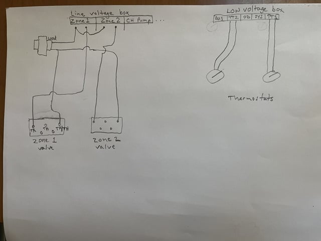 0
0 -
First, if you wired it like your drawing I find it hard to believe you are getting 13 VDC anywhere, ever. Unless it is just some odd ghost voltage your meter is seeing.
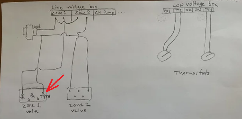
Second, as far as I can tell the TR/TH terminal (Red Arrow) is just a convenience connection point, often used to connect the transformer to a thermostat wire instead of using a wire nut, it does nothing inside the zone valve. So effectively you have only one wire going to the zone valve, look at the zone valve manual. Which it why the pigtail wired version of the zone valve only has 4 wires.
There is proper sequence of operation when using zone valves. It is #6 text below, it is in the boiler manual multiple times, however the paragraph number changes. The thermostat call for heat, zone valve activates, when the zone valve opens all the way it activates the boiler. Your present wiring does not support that operational sequence. The wiring diagram below supports that sequence of activity.
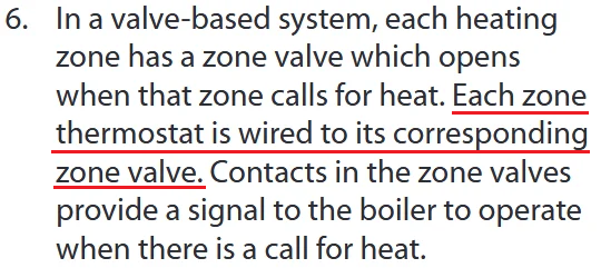
Your thermostats are wired to the boiler, they should be wired to the zone valve(s).
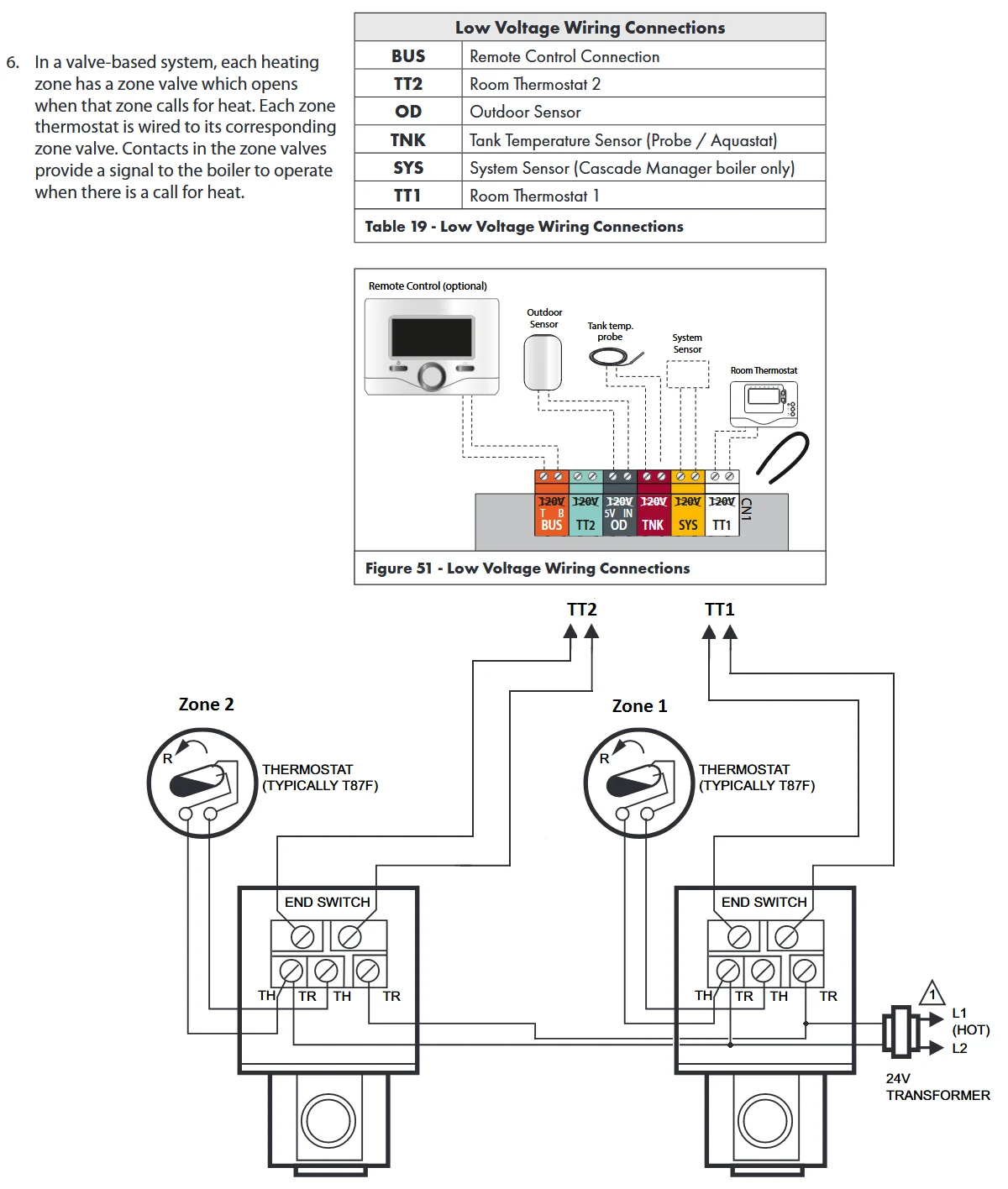
" Can someone draw me a sketch on how this should be wired. " this wiring diagram directly above is not clear to you ? This is the second time I posted it.
Hint: you need to abandon the connections to the line voltage terminals and only use the low voltage terminals.
National - U.S. Gas Boiler 45+ Years Old
Steam 300 SQ. FT. - EDR 347
One Pipe System2 -
when you say its piped primary secondary what method are you using to hydraulically separate the 2 loops, closely spaced tees, a low loss header, or a buffer tank?
0 -
109A_%, Sorry, I did not look at it close enough and thought it was from the Honeywell manual. Thanks for the help. So does anything get connected to the Line Voltage Junction Box? Manual shows a dry connection to the transformer per the diagram you posted above.
0 -
I believe the boiler's line voltage contacts are actually for (or better suited for) when the zoning is done with circulators and not with zone valves.
" Manual shows a dry connection to the transformer per the diagram you posted above. " I do not know what exactly you are referring to.
All this wiring shown below (line voltage contacts stuff) would be abandoned, it is not applicable for what you are trying to do. As per the text in the paragraph from the manual about zone valve use. The transformer would get repurposed to power the thermostat circuit and the zone valve motors.
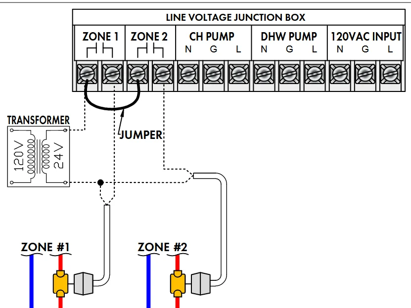 National - U.S. Gas Boiler 45+ Years Old
Steam 300 SQ. FT. - EDR 347
One Pipe System1 -
@109A_5 does a great job of explaining the wiring. But sometimes a picture is better. in the diagram from #6 in the I/O manual I have made the circuit a little simpler.
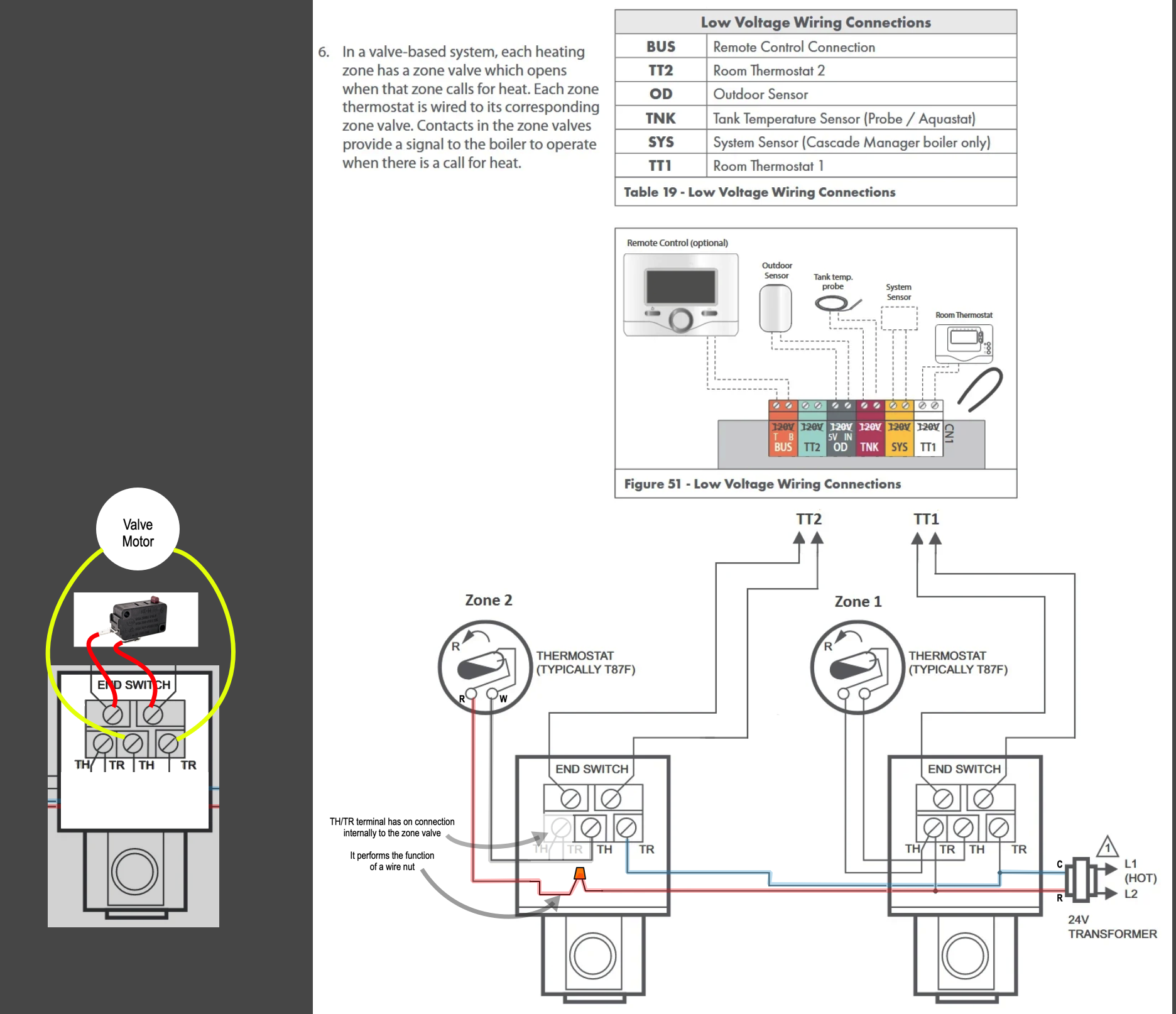
The illustration to the right of the #6 diagram shows what the other side of each terminal is connected to inside the box.
TH is connected to a yellow wire that goes to the motor. TR is connected to the other yellow wire going to the motor. When 24 volts is applied across the TH and TR terminals, the motor will open the valve. connecting only one wire to the TH/TR screw will accomplish nothing
On the other side of the end-switch terminal screws are two red wires connected to a switch. That switch closes, much like a thermostat closes on a call for heat, connecting the two terminals together—just like closing a switch to turn on a light bulb.
In this case, you would run two wires from the end switch and connect them to either 1TT or 2TT on the boiler.
What you show this drawing as the wiring you have:
This is troublesome to me because you have a line voltage zone output connected to a low voltage transformer. and the arrow that @109A_5 added to your diagram is basically connecting only one wire to a wire nut, like this:
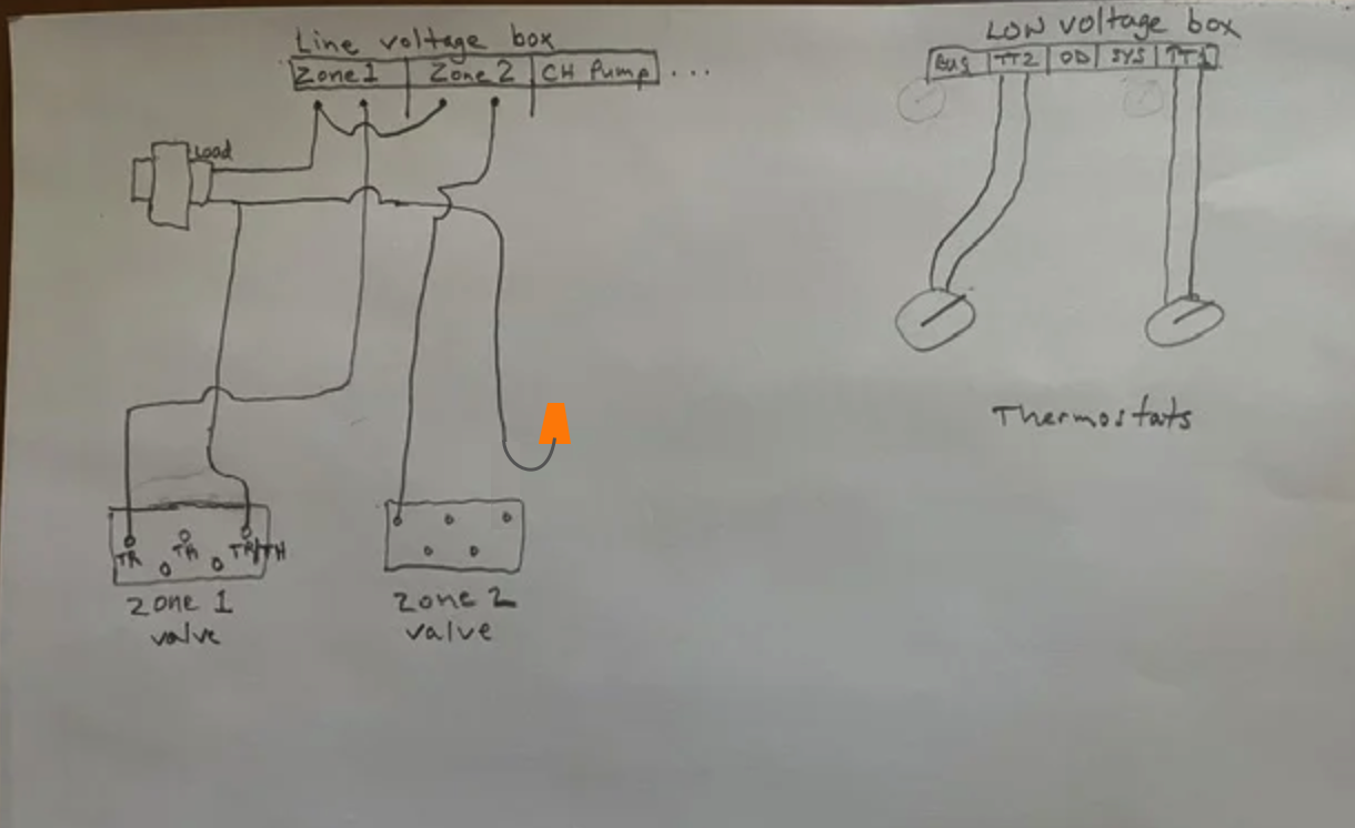
Because TH/TR terminal has nothing connected to the other side of the screw terminal inside the box
Edward Young Retired
After you make that expensive repair and you still have the same problem, What will you check next?
0 -
OK thanks so much for everyone's help on this, you all have been awesome. I will rewire according to these comments. Apparently the NTI instructions suck for my application and really threw me off, although the rest of their manual is pretty good. I will let you know how it turns out.
1 -
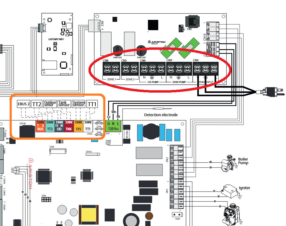
The confusion could be that terminal strip labeled Line Voltage Junction Box
I believe the Zone 1 & 2 are dry contacts
Usually UL requires a separation between line voltage and 24V. That cardboard strip you see in some relay boxes.
Bob "hot rod" Rohr
trainer for Caleffi NA
Living the hydronic dream0 -
I am running manual heat now-disconnected the wires from the transformer and opened the zone valves and it operates on the t stats connected to the boiler-turns the circulator pump on/off. Will rewire tomorrow. Am in upstate NY night temps are 40s.
1 -
Hopefully with @EdTheHeaterMan's additional illustrations it will help with @billyboy01's understanding.
@hot_rod I think you will find the Line Voltage Junction Box and the Low Voltage Wiring Connections are separated. " I believe the Zone 1 & 2 are dry contacts " I believe you are correct.
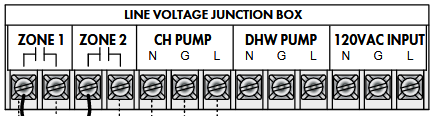
 National - U.S. Gas Boiler 45+ Years Old
Steam 300 SQ. FT. - EDR 347
One Pipe System0 -
Sounds good.
National - U.S. Gas Boiler 45+ Years Old
Steam 300 SQ. FT. - EDR 347
One Pipe System0 -
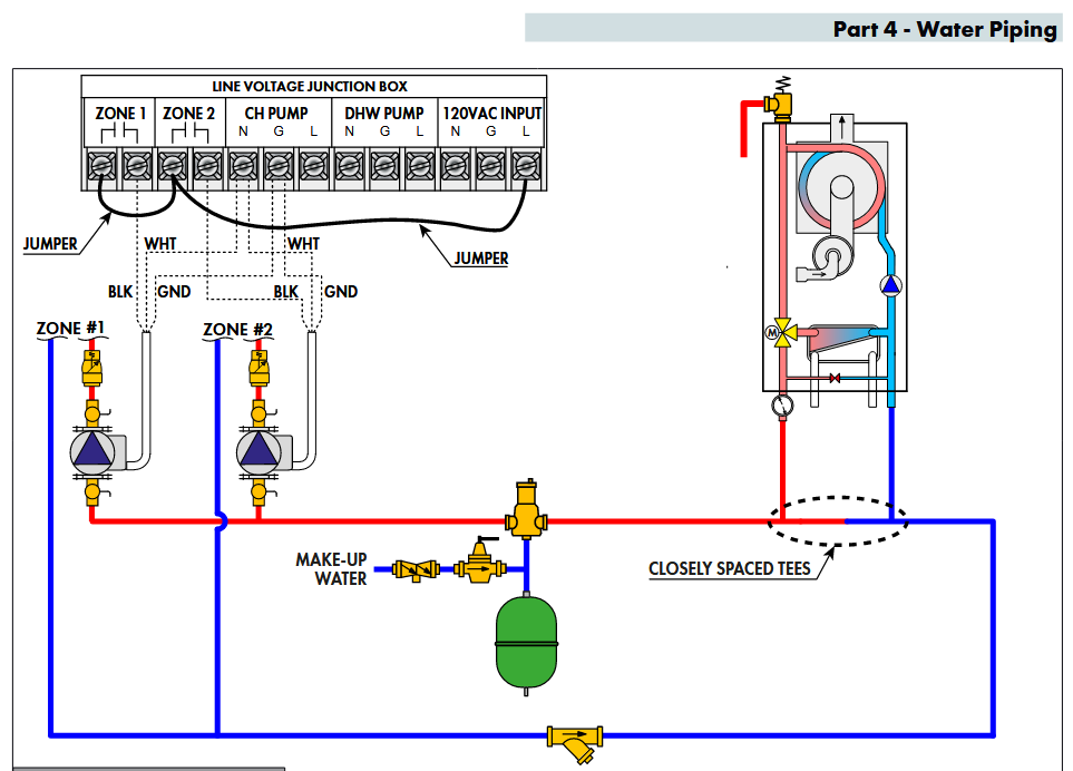
Just as an informational example, not applicable in @billyboy01situation. The Zone 1 and Zone 2 contacts are used to control circulators.
 National - U.S. Gas Boiler 45+ Years Old
Steam 300 SQ. FT. - EDR 347
One Pipe System1 -
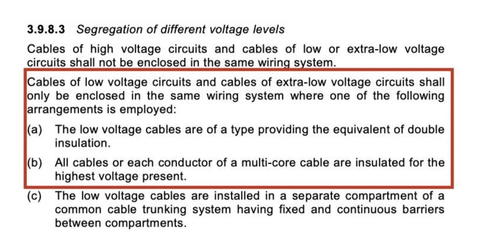
I believe if you put 24v on those dry contacts, there needs to be a physical separation between the high voltage terminals, to be code compliant.
You see most of the early hydronic relay boxes had a fiber divider over the 120v terminal strip, provision C of the code.
Maybe that has changed?
 Bob "hot rod" Rohr
trainer for Caleffi NA
Living the hydronic dream0 -
"I believe if you put 24v on those dry contacts, there needs to be a
physical separation between the high voltage terminals, to be code
compliant."OK I see what you are getting at. And I agree with you.
Which is one reason why I think that illustration using only two wires of a 24 VAC zone valve (or simply a two wire zone valve) being switched by the Zone 1 & 2 dry contacts is a poor way of making it work and not really best practice.
National - U.S. Gas Boiler 45+ Years Old
Steam 300 SQ. FT. - EDR 347
One Pipe System1 -
Confusing, but this can generally be wired properly by using individual conductors for the 24-volt Zone 1 and Zone 2 circuits with insulation rated for at least the highest voltage present in the enclosure—typically 600 V-rated THHN/THWN or equivalent—for the portion of the wiring that is inside the line-voltage junction box. The conductor size is based on the low current of the 24-volt circuit; the higher insulation rating is used because the conductors are routed in the same enclosure as the 120-volt wiring. The boiler manufacturer’s wiring instructions and applicable code requirements for separation and routing still need to be followed. This is one option for wiring the system as long as the wires insice the NTI enclosure are rated for the task.
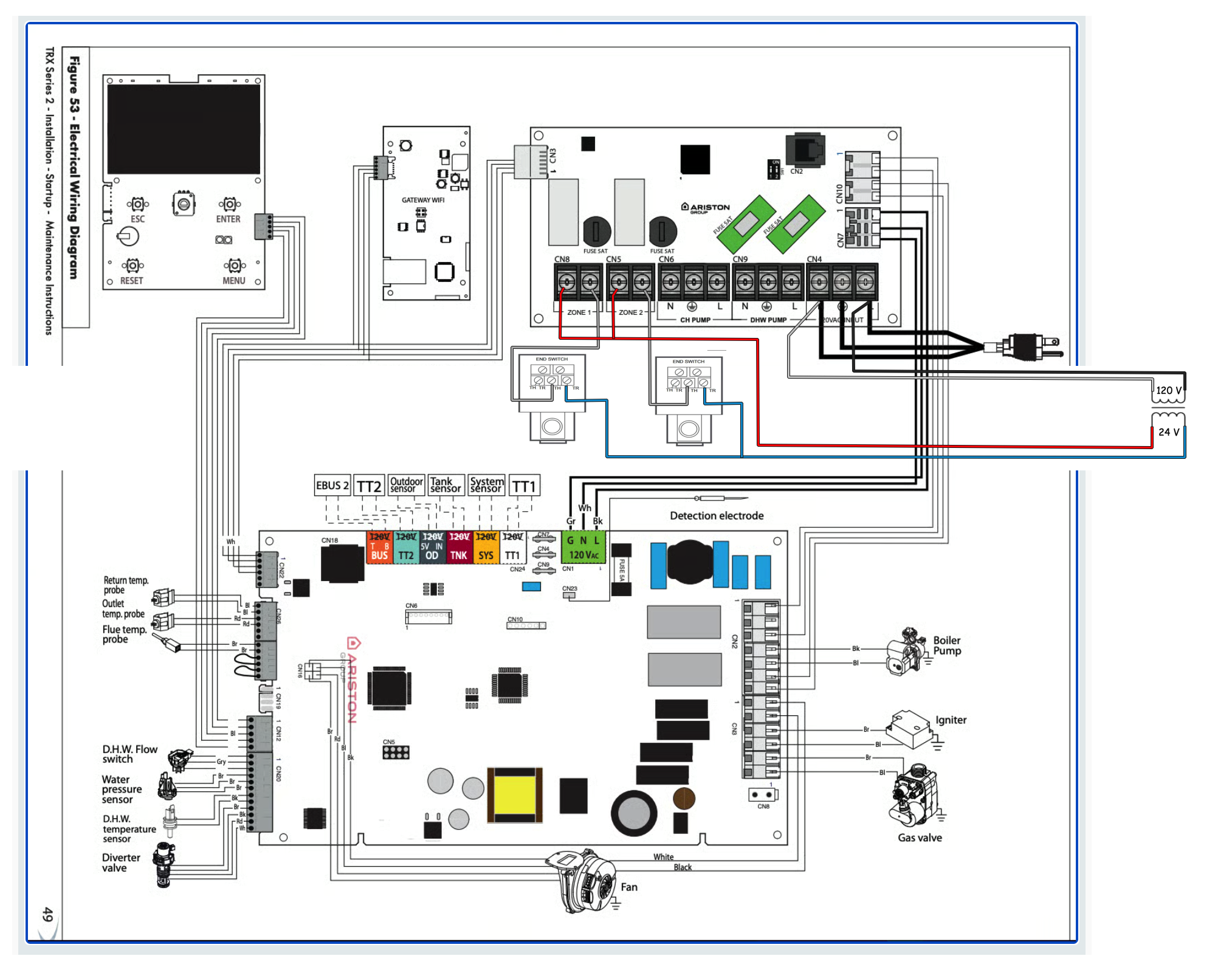
Thermostst calls for heat in a zone, the Zone 1 contacts activate the zone valve. The trouble with this diagram is that the CH circulator may operate against a closed valve if the zone valve fails to open. There is no way for the CH pump to know not to operate if the valve fails in the closed position. In oorder to make that happen, you could use the zone valve end switch (that is the same end switch on the line voltage Honeywell V4043 valves) to break the CH circulator power so if the valve fails to open the end switch will not close the circuit to the CH pump like this diagram shows:
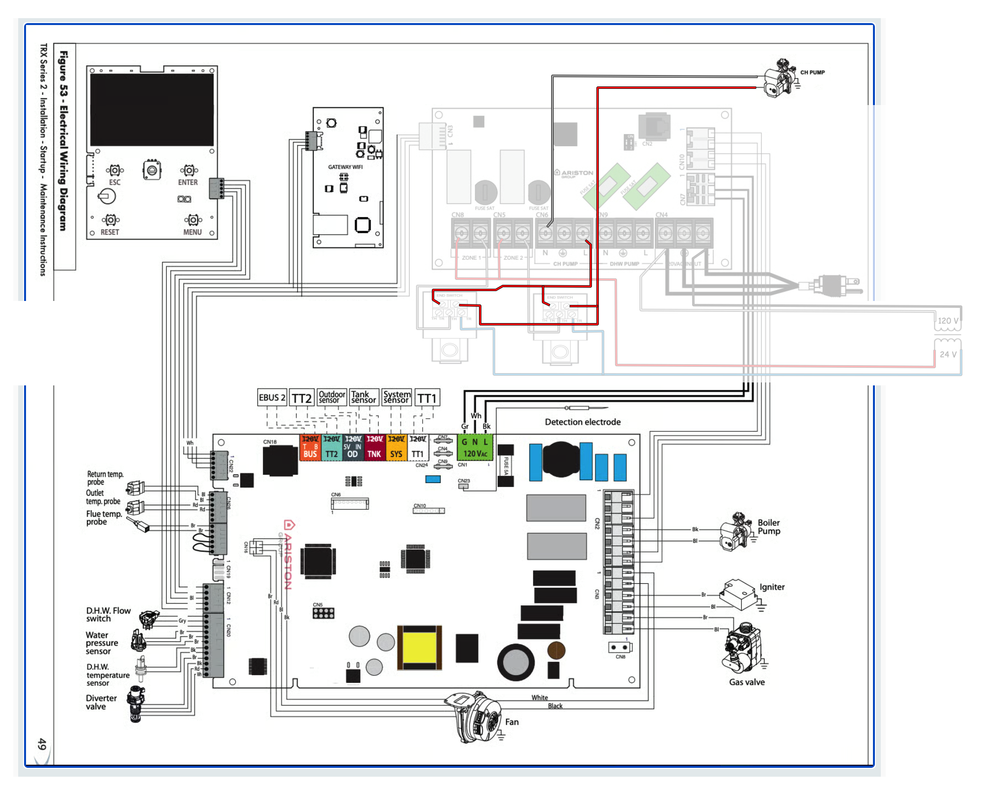
The problem with this diagram is that you have two different voltages connected to the zone valve. so the 4 wires must be individual conductors for the 24-volt Zones with insulation rated for at least the highest voltage present in the enclosure—typically 600 V-rated THHN/THWN or equivalent and the other two wires in rated for the 120 V of the circulator circuit. this can be confusing for future service, since this is not a standard procedure.
So you have the option of using one of the diagrams above or, to wire the zone valves as intended with a separate source and only using the end switches to connect to TT1 and TT2 respectively on the NTI as shown below.
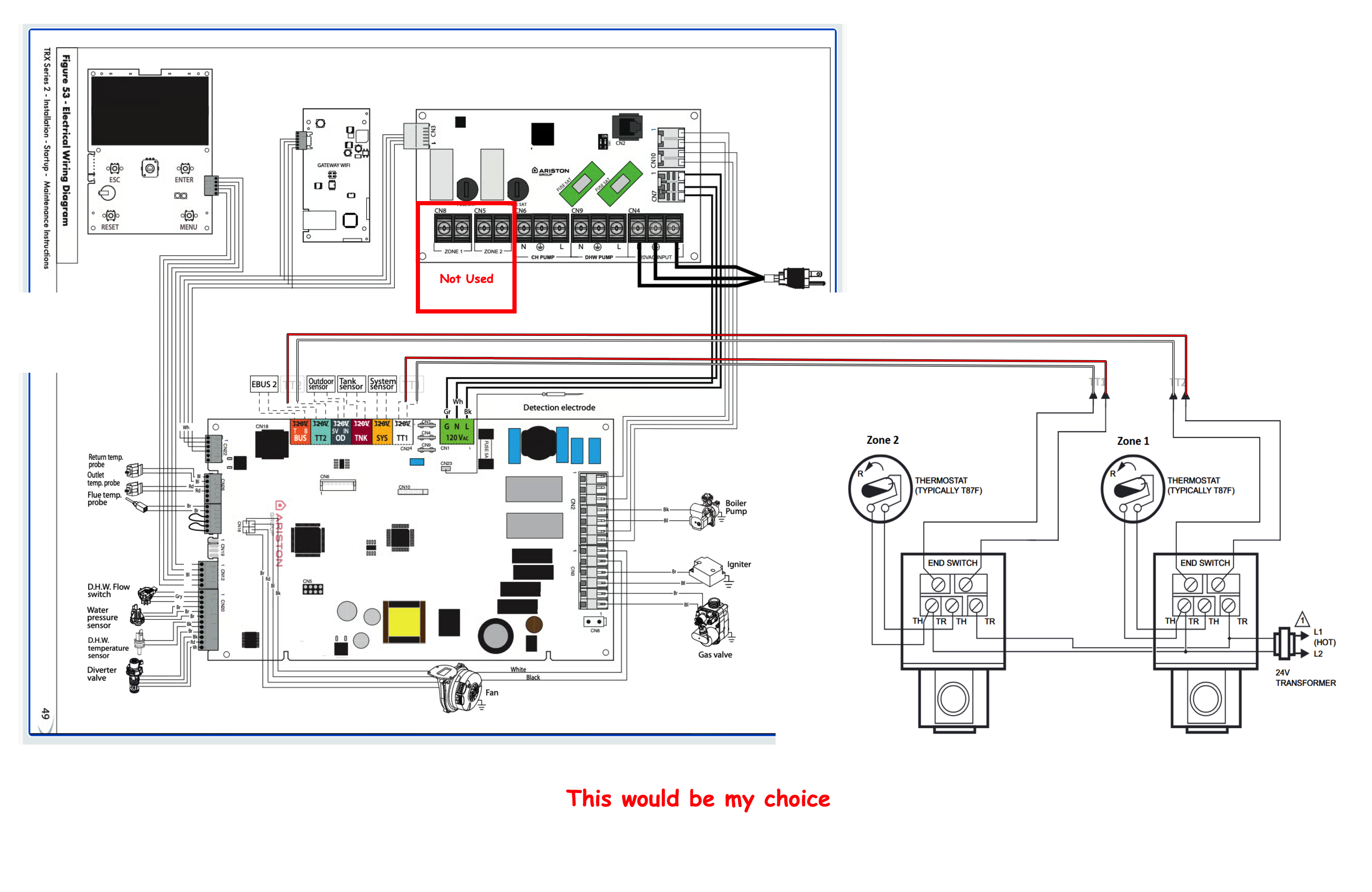
There is more than one way to Get 'er Done". …and that is what makes this business so much fun!
Edward Young Retired
After you make that expensive repair and you still have the same problem, What will you check next?
0 -
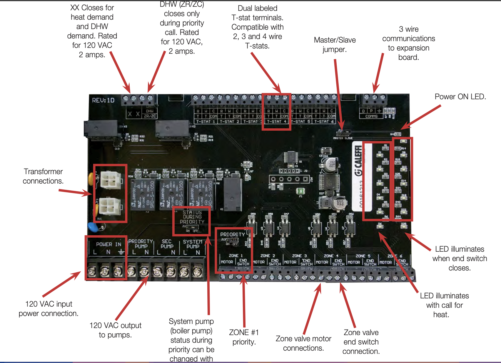
I'd say for the novice hydronic control electrician, the relay boxes make it almost impossible to screw it up. The thermal links offer protection protects against meltdowns or destroying expensive components Indicator lights to prove the logic and troubleshoot. Three thermostat terminals for power stealing stata, ZV wire to bottom. Standard thermostat wire from XX to boiler heat demand.
 Bob "hot rod" Rohr
trainer for Caleffi NA
Living the hydronic dream2 -
All I was trying to do is make it work correctly (Best Practice) with the equipment @billyboy01 already had. Sure you can add more equipment and better wire, but it will work nicely without any extra special stuff. If there were more than 2 zones that would be another story.
And also have the proper control sequence with the existing equipment, Thermostat calls for heat activating the zone valve, when the zone valve proves it is open it calls the boiler.
Just for curiosity sake I would like to read the code, as @hot_rod suggests I think I have always seen a barrier of some sort, not just better wires. There may be an exception for using better wires.
National - U.S. Gas Boiler 45+ Years Old
Steam 300 SQ. FT. - EDR 347
One Pipe System0 -
Thanks for the post EdTheHeaterMan, I don't feel like such a dumb*ss after reading your post since my original wiring was close. I would just need to switch the one wire on the zone valve to the TH terminal but will rewire following yours and 109A-5's recommendations to be safe. Hot_Rod comment about adding a control box is also useful since I have more than just 2 zones but have ordered an NTI N-Link controller for the other zones that plug into the BUS contacts on the boiler low voltage box. Thank you all!
0 -
The thing I don't like about those custom solutions like the "NTI N-Link controller" by the boiler's manufacture is when they fail they are often hard to find. Since you actually have more than 2 zones @hot_rod's more generic solution is easier to maintain. And often more straight forward to initially wire up.
National - U.S. Gas Boiler 45+ Years Old
Steam 300 SQ. FT. - EDR 347
One Pipe System0 -
just use a 3rd party external relay. I guarantee a standard 3rd party zone controller is easier to install, easier to source a replacement, easier for a tech to understand, and almost definitely less expensive.
0



Categories
- All Categories
- 87.8K THE MAIN WALL
- 3.3K A-C, Heat Pumps & Refrigeration
- 60 Biomass
- 430 Carbon Monoxide Awareness
- 133 Chimneys & Flues
- 2.2K Domestic Hot Water
- 6K Gas Heating
- 124 Geothermal
- 170 Indoor-Air Quality
- 3.9K Oil Heating
- 79 Pipe Deterioration
- 1.1K Plumbing
- 6.7K Radiant Heating
- 397 Solar
- 16.1K Strictly Steam
- 3.5K Thermostats and Controls
- 56 Water Quality
- 51 Industry Classes
- 51 Job Opportunities
- 18 Recall Announcements