5-ton Trane system, 0.8 TESP, blower failed after ~2 years — how concerned should I be?

I have a 5-ton Trane system serving about 3,054 sq ft.
Outdoor unit: 4TTR5060N1000AA
Indoor furnace/blower: S8V2D120M5PC, variable-speed ECM
Original blower motor failed after about 2 years and was replaced under warranty.
Static was measured twice at about:
- Return: -0.35 in. w.c.
- Supply: +0.45 in. w.c.
- TESP: ~0.80 in. w.c.
The system currently cools well at 76–77°F, humidity is generally 48–54%, and room-to-room temperature difference is about 3°F after prior balancing.
One tech calculated duct capacity at roughly 2,120 CFM return and 2,165 CFM supply, but that was based on duct sizes, not instrument-measured airflow.
Trane’s blower tables for this furnace show performance data through 0.9 in. w.c., which is why I’m trying to understand how to interpret the 0.8 reading in real-world use.
My main questions:
- Is 0.8 concerning enough to investigate further on a variable-speed ECM system that otherwise performs well?
- Could 0.8 reasonably contribute to an ECM blower failing after only about 2 years?
- Would you first measure actual CFM, blower setup, filter pressure drop, and coil pressure drop before changing any ductwork?
- How do you interpret a manufacturer blower table that publishes airflow through 0.9 when 0.5 is often quoted as the design/rated static?
I’m trying to determine whether this is a genuine restriction issue that should be corrected or simply a higher-than-ideal but common operating condition.
Comments
-
first I hope they registered that equipment so you get the full 10 years warranty.
See how the contractor deals with it. Is that .8 the calculated number of the controls or the actual numbers tested with the manometer
0 -
ECM motors fail. You can do a conversion from ECM to PSC motors. They sell kits for that. If you have to pay for a new ECM motor you will realize why.
0 -
Thanks for the response. The @ pecmsg 0.8 was an actual field measurement with a digital manometer, not a number calculated by the furnace controls. The tech measured about -0.35 in. w.c. on the return side and +0.45 in. w.c. on the supply side.
I later checked the exact test locations and found the +0.45 supply reading was taken after the evaporator coil, so that 0.8 was not measured at the correct furnace TESP points. My furnace nameplate shows Maximum External Static Pressure: 0.70 in. w.c., so I’m going to have it retested correctly.
On the warranty, unfortunately the equipment currently shows the 5-year base parts warranty, not the 10-year registered warranty.
0 -
@ EBEBRATT-Ed Thanks for the suggestion. Mine is still under the Trane parts warranty for now, so I’d probably stay with the OEM ECM motor while it’s covered. My main concern is figuring out whether the static pressure or airflow contributed to the first motor failing after only about two years.
Have you actually done an ECM-to-PSC conversion on a Trane S8V2 or similar variable-speed furnace, and did it affect airflow control or comfort?
0 -
.8 is not bad. Most systems are .6 or higher.
is this a zoned system?0 -
you type:
“I later checked the exact test locations and found the
+0.45 supply reading was taken after the evaporator coil, so that 0.8 was not measured at the correct furnace TESP points. My furnace nameplate showsMaximum External Static Pressure: 0.70 in. w.c., so I’m going to have it retested correctly.”
I hate to be so pessimistic- can you take pics where these measurements were taken? Wrong spot then these numbers are useless. You would think all the decent technicians out there nowhere to take the measurements. But I would not bet my life on it.if you have the energy to take pictures, take them from several steps back and try to draw an arrow. If you take the picture too close, I won’t have any frame of reference.
.08 doesn’t alarm me at all.
do you have a zoning system or is this just one thermostat?
Something doesn’t add up though- the tech used his duct-u-lator for that estimate? Thats a reasonable method to get a basic guess. If he guessed reasonably close, then something isn’t adding up perfectly well
0 -
Having a 2 year old ECM motor fail is not exactly atypical even when static pressure is in range.
 1
1 -
especially given there are still parts and designs around that were compromises to get around covid shortages.
 1
1 -
An AC evap coil can add anywhere from 0.1 to 0.4 IWC or more to your TESP, depending on how clean or dirty the coil is. So at a minimum you're probably already at 0.9 IWC when you add in the coil, and possibly over 1.0.
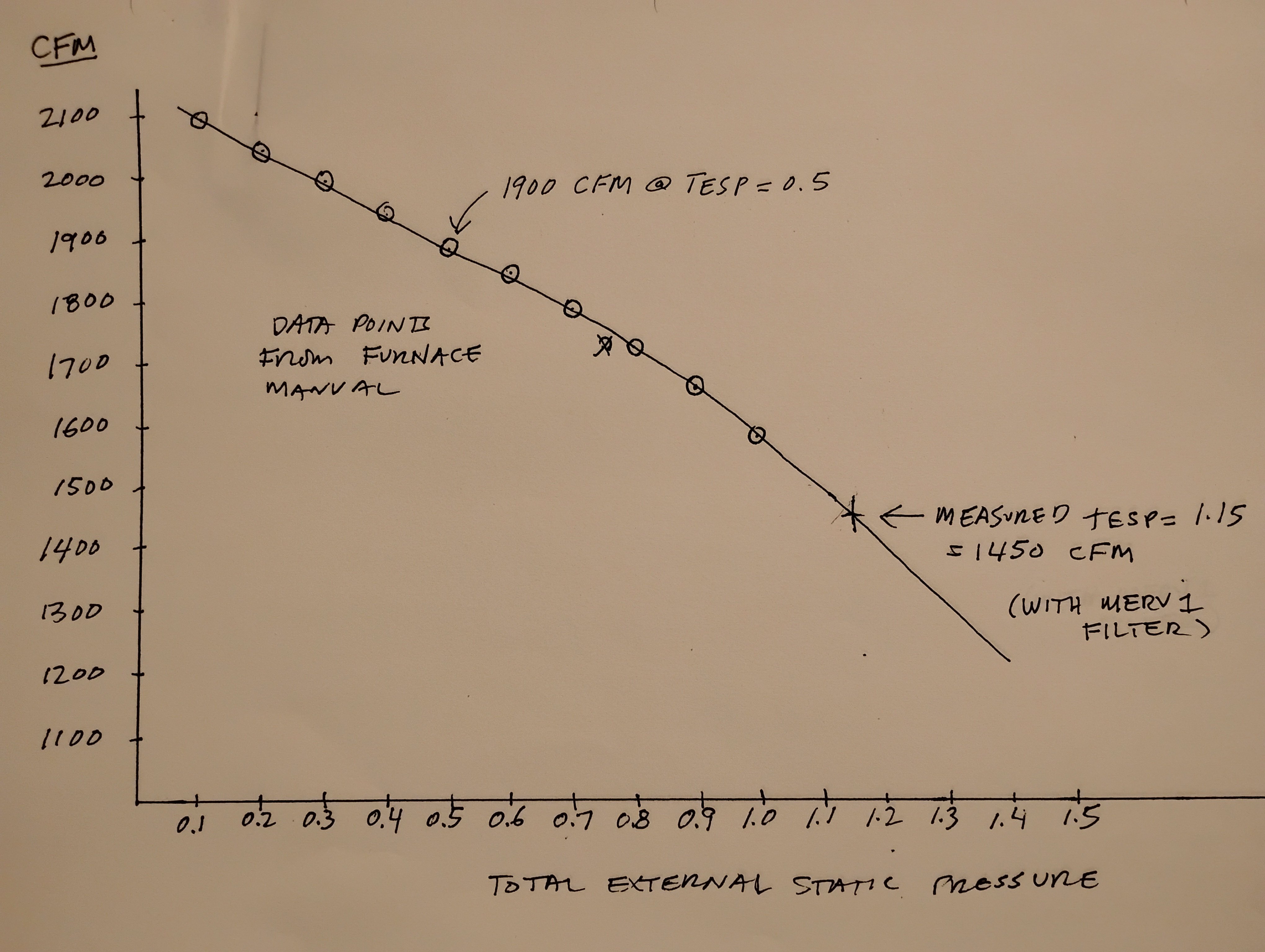
You can plot the data points from the chart of CFM vs TESP on graph paper, then extrapolate the curve beyond the 0.9 max they give you. It won't be exact, but if you approximate the curve you can get a good idea of CFM at your measured TESP.
At some point the CFM's can get low enough that the furnace will start shutting down on high limit, which is not good for the heat exchanger if it happens repeatedly. We had that problem with our church's furnace, which turned out to have unacceptably high TESP because the installer screwed up the return plenum sizing. We had no recourse because there wasn't enough space in the furnace room for a proper-sized return plenum, so we were forced to lock the furnace in low-fire mode to keep it from overheating. So now our new furnace limps along at 40% rated capacity. But at least the ECM won't burn out.
So if your max spec TESP is 0.7 and it's actually 0.9 or higher because the installer messed up on duct sizing, I would put the pressure on them to fix it. They'll say you can't prove the higher TESP caused the ECM to fail, then you say they can't prove it didn't.
Take a look at the ECM lifetime chart in the following HVAC blog. A typical ECM running at 0.5 IWC can last 15 years. A Typical ECM running at 0.8 IWC or higher has an expected life of 2 years, which is right when your ECM failed. Putting a new ECM in without fixing the high TESP is just setting up for another failure in 2 years.
https://northernonehour.com/blog/high-static-pressure-hvac-symptoms-fixes-twin-cities/
 1
1 -
Power issues can take out motors also. Surges, lightning, bad grounding.
The motor itself or the control module on the motor?
Bob "hot rod" Rohr
trainer for Caleffi NA
Living the hydronic dream0 -
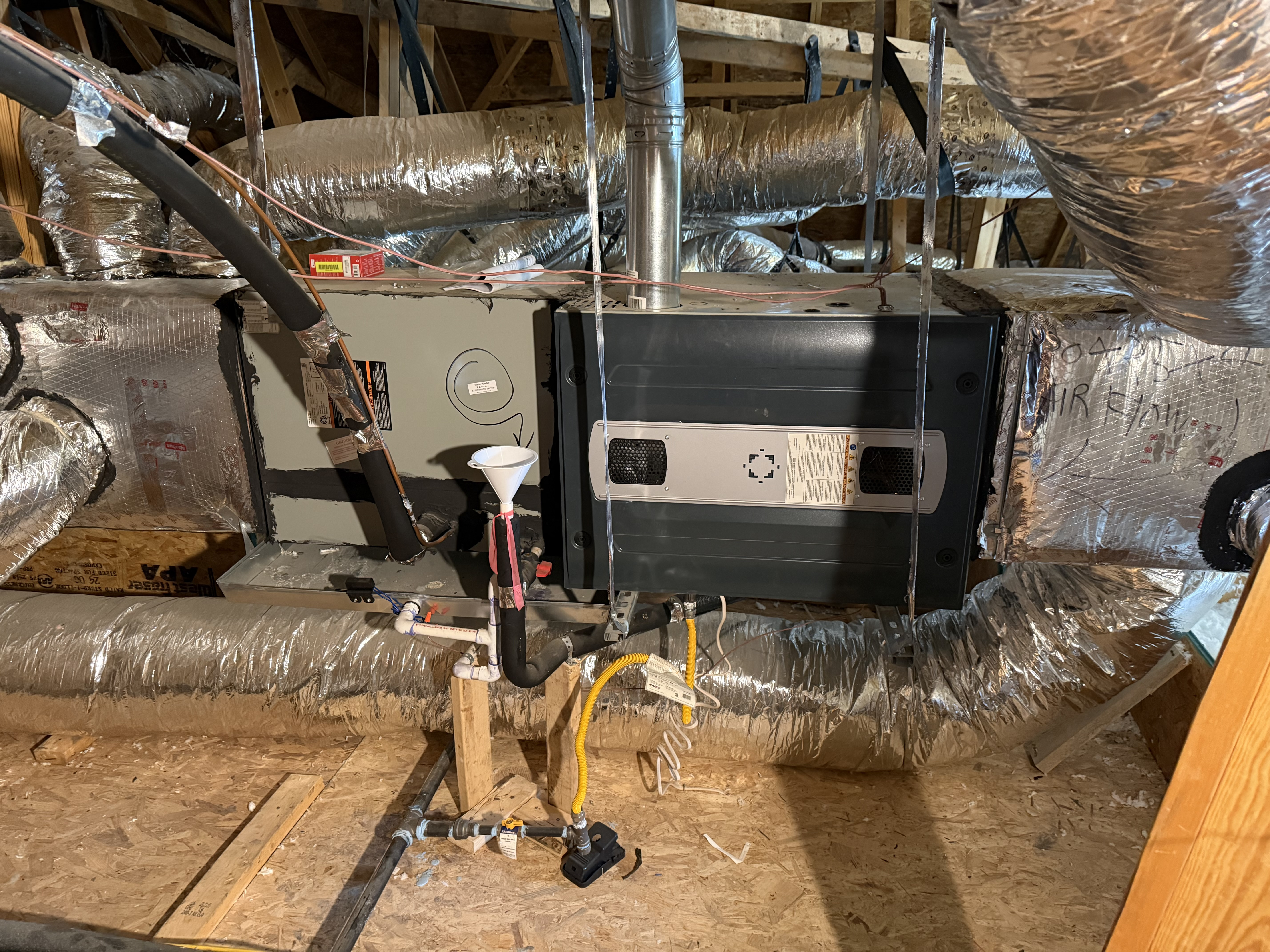
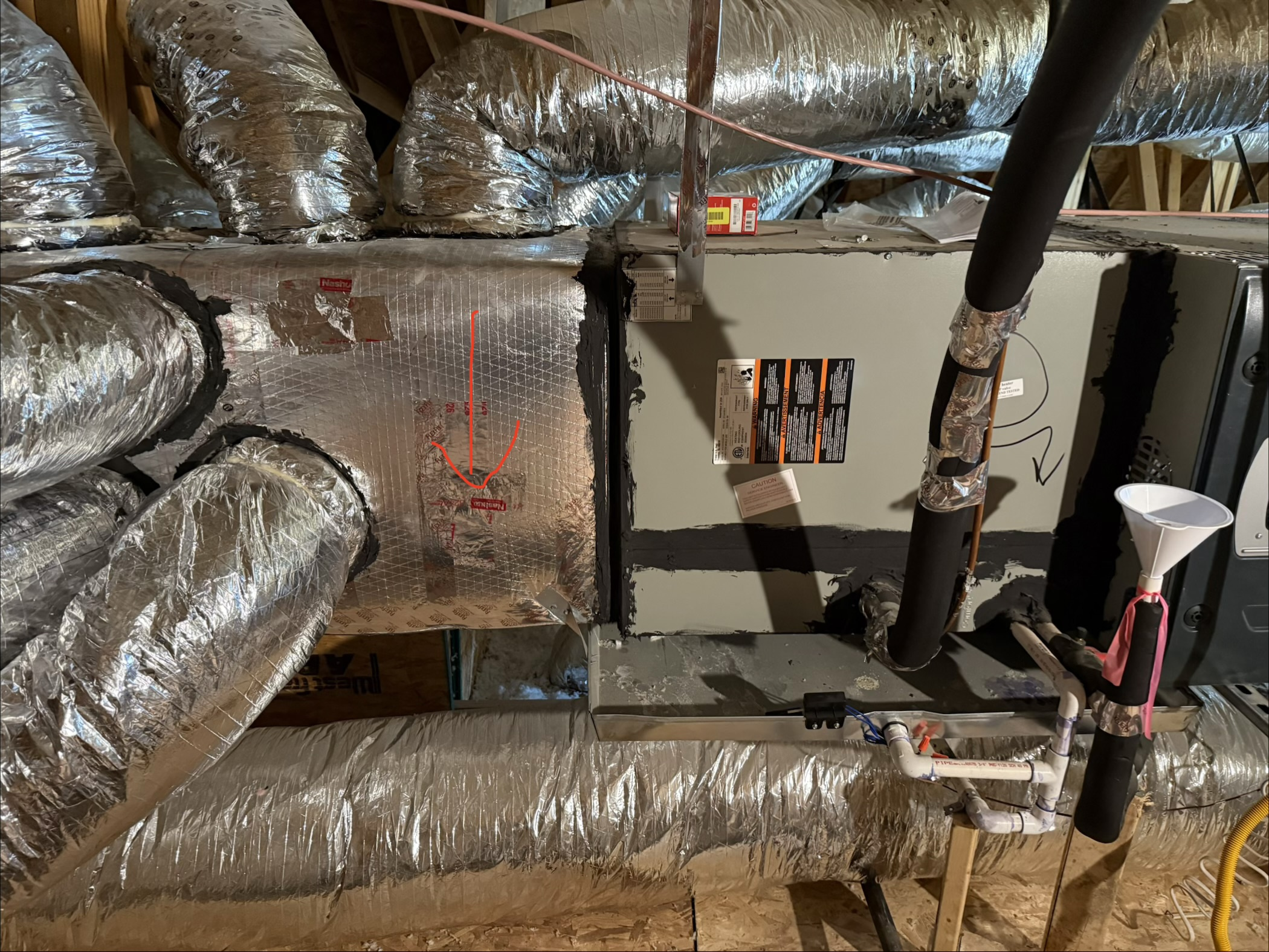
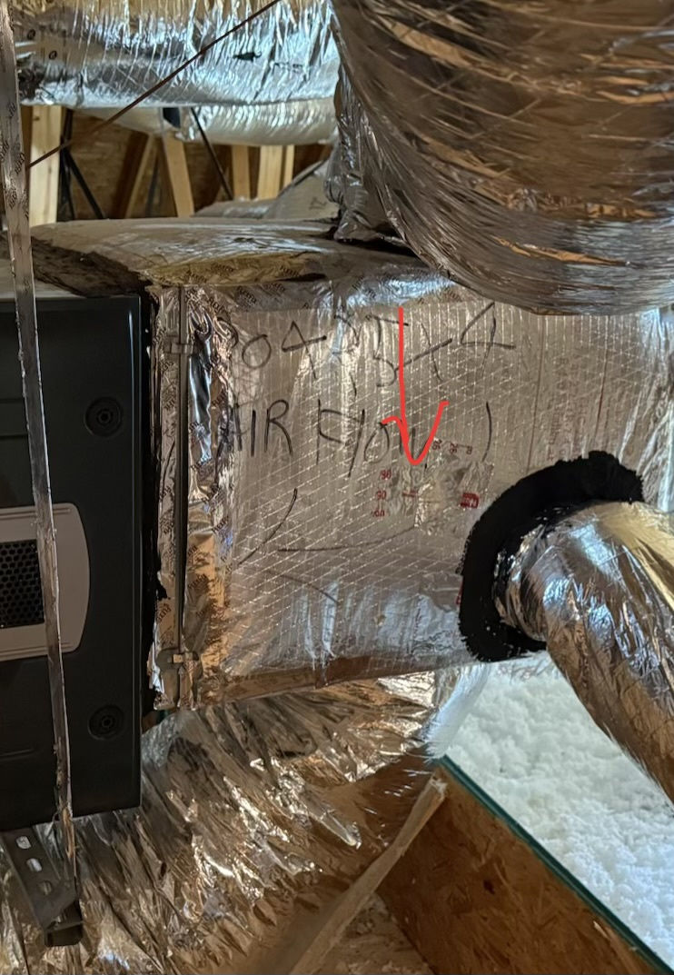
@GW GW Here are the wider photos with the previous test locations marked.
- Photo 1: full-system view for orientation.
- Photo 2: red arrow marks the previous +0.45 in. w.c. supply-pressure test point. This point is downstream of the evaporator coil.
- Photo 3: red arrow marks the previous -0.35 in. w.c. return-pressure test point.
The airflow direction is from the return side on the right → furnace → evaporator coil → supply ductwork on the left.
Based on these locations, am I correct that the +0.45 supply reading was not taken at the proper point for comparing furnace TESP to the furnace nameplate maximum?
0 -
there’s no way with all that flex your TESP is only .8 !
0 -
was there are properly working blower when it was measured?
0 -
0
-
they forgot the “1” in front of the .8 !
 1
1 -
@tejvem said:
"Based on these locations, am I correct that the +0.45 supply reading was not taken at the proper point for comparing furnace TESP to the furnace nameplate maximum?"
You are correct. They measured static for the supply downstream of the evap coil, which is incorrect and will give too low a reading. The correct place to measure static for the furnace supply is between the evap coil and the furnace. That is going to add anywhere from 0.1 to 0.4 to your TESP.
1 -
@jesmed1 Thanks for the detailed explanation and the real-world example. That’s exactly why I want to get the measurements corrected before drawing any conclusions.
Since the previous +0.45 supply reading was taken after the evaporator coil, I’m going to have the supply pressure measured between the furnace and coil and also measure the coil pressure drop separately. That should tell me whether the actual furnace TESP is 0.9, over 1.0, or something else.
I’m also going to document the current blower airflow setting so I can compare the correctly measured TESP with the Trane blower-performance table.
If the properly measured TESP comes back above the furnace’s 0.70 in. w.c. nameplate maximum, then I’ll have objective documentation to take back to the installer/builder and ask them to identify and correct the restriction.
I saw the ECM-life chart you linked. I’m treating that as supporting information rather than proof that the high static caused my particular motor failure, but an early ECM failure combined with documented operation above the manufacturer’s static limit would definitely make me want the underlying issue corrected before simply replacing motors again.
One question: if my measured TESP ends up above the highest value published in Trane’s blower table, would you actually extrapolate the curve, or would you consider the airflow estimate too uncertain at that point and want a field CFM measurement?
0 -
@jesmed1 Thanks, that confirms what I was thinking. I’m going to have the supply pressure retested between the furnace and evaporator coil and also measure the pressure drop across the coil separately. I understand the coil could add roughly 0.1–0.4 in. w.c., but I’ll wait for the actual measurement rather than estimate it. Once I have the corrected furnace TESP, I can compare it directly with the 0.70 in. w.c. nameplate maximum.
0 -
Hmmm, return reading before or after the air filter?
Off topic, but the secondary drain in the evaporator has a valve and a funnel. Whats up with that? I won't ask about the T&P.
0 -
https://www.hvacrschool.com/total-external-static-pressure-tesp-a-basic-review/
0 -
wrong spots——that's the duct system he measured.
Is there an air filter on the furnace or is that somewhere else?
0 -
I see a 1” Slot on the cabinet
0 -
doesn't mean there a filter there
If there IS- wrong spot to test static
If there ISN'T, —it's a fine place to test static.
0 -
@GW made a good point about the return static measurement point. There can't be any flow obstacles between the probe and the blower motor (eg filter, coil, etc), either on the return or the supply side, or the measurements will be wrong. So find out where the filter is and make sure they take the return static in a location where the filter is not between the probe and the blower motor. In addition to taking the supply static before the coil…
As to your question about CFM's, the actual CFM's don't matter so much as long as you're getting adequate cooling and heating in every room, and as long as the furnace isn't overheating in winter or the coils icing in summer. I extrapolated my CFM curve more out of interest than necessity, and my conclusion was that at a measured TESP of 1.15 IWC we were probably getting around 1450 CFM's, which is 24% lower than the 1900 CFM's we would have gotten at a max allowed TESP of 0.5 IWC.
That was a big enough discrepancy to cause our furnace to overheat repeatedly. But if you aren't getting overheating fault codes, then your CFM hit may not be as bad as ours was. Still, any TESP over your max allowable of 0.7 is a potential concern because of possible ECM overloading. And if/when the TESP problem gets fixed, your CFM's will automatically increase accordingly. So if you're comfortable now with the existing CFM's, you'll be comfortable after the TESP (hopefully) goes down.
As to your question in the original post about "whether this is a genuine restriction issue that should be corrected or simply a higher-than-ideal but common operating condition," that's kind of a false choice. Anything above the max TESP rating of the furnace is technically a violation that should be corrected, but many HVAC companies rely on homeowner ignorance and don't care that the system they installed has a TESP of 0.8 when the furnace has a max spec of 0.5. As long as they don't get complaints, they don't care, and most of the time they get away with it.
So anything higher than 0.7 for your furnace is a "genuine restriction issue" due to undersized ductwork, sharp turns, bad geometry, clogged coils, dirty filters, etc, that "should" be corrected. And the ECM doesn't care where the "correction" happens. It could be a lower-MERV filter, or cleaning the evap coils, changing some duct runs, adding a return, etc.
You paid for a system to work as spec'd by the furnace mfr, which was a TESP of 0.7 max. Instead you got a system probably closer to 0.9-1.0 or more, so maybe 30%-40% higher, which probably fried one ECM and will probably fry more. Make them fix it.
FWIW, here's my chart. You can see the curve bends down a little as TESP increases, so it's not linear, and as a result I had to eyeball the extrapolation. But it's not a huge non-linearity, so I think it's probably accurate to within 100 CFM or so.
 0
0 -
the ecm motor tries to get to what it thinks it needs to get the selected flow, right? so if the esp is out of spec it will try to produce extra power to to increase flow and that is why esp out of spec is bad for ecm motors.
0 -
ECM- if it's a "variable Speed", YES.
If it's the basic "constant Torque", then no.
I've had my own internal confusion with this. Carrier Bryant says their (on some models) motors are "variable Speed", but i think that's false. It's the same lane dip switch set up as the basic motors.
For many years we did Lennox, those variable speed motors were in fact variable speed.
1 -
@HVACNUT The -0.35 return reading was taken before the air filter. The filter is a 4-inch Honeywell MERV 11 located at the furnace.
The secondary drain/valve/funnel setup is original to the builder/HVAC installation. I haven't modified it, so I'm not sure why they installed it that way.
1 -
@pecmsg Thanks for the link. That cleared up the test-point issue for me. Based on the article, the return reading should be taken between the filter and blower, and the supply reading between the furnace and evaporator coil, with the filter and coil pressure drops checked separately.
I also see the 1” slot you mentioned. It looks like a 1” slot from the outside, but the filter installed there is actually a 4” Honeywell MERV 11.
The earlier 0.8 reading had the supply probe after the coil, so it doesn’t appear to be the proper furnace TESP for direct comparison with the 0.70 nameplate rating.
0 -
@jesmed1 Thanks, this helps a lot. The filter is a 4” Honeywell MERV 11 at the furnace. The -0.35 return reading was taken before the filter, so based on your point and @GW ’s point, that was not the correct return location for furnace TESP. The +0.45 supply reading was also taken after the evaporator coil, so that wasn’t the correct furnace supply location either.
So my first priority now is to get a proper baseline TESP with the return probe between the filter and blower and the supply probe between the furnace and coil, and then check the filter and coil pressure drops separately.
Your explanation about CFM also makes sense. The house is cooling well and I haven’t seen overheating or icing fault codes, so I’m not going to chase a theoretical CFM number first. I mainly want to establish the correctly measured TESP and see whether it is actually above the 0.70 rating.
I’m also keeping the cause of the motor failure open for now. Until the TESP is measured correctly, I don’t want to assume it is really 0.9–1.0 or that static definitely caused the failure. But given the early motor failure and the 0.70 maximum rating, I definitely want the airflow/static issue properly diagnosed.
0 -
yes that’s not good
some doods don’t bother to set the cfm when installing new equipment. Example- your furnace come with a 4 ton blower but you have a 3 ton ac system. That furnace control must be set for the correct air flow. Not saying that’s what’s happening here but the numbers you’re describing are way off. In a bad way
0 -
The part about this that bothers me is it really seems like it shouldn't be possible.
The motor is programmed with firmware to run a specific way. If that programming allows it to run outside of a safe condition, that's a bad design.
If it allows it to spin up and down "hunting" because of some outside issue, that's a bad design. It either shouldn't react that fast to changes or it should alarm out.
Especially for what these motors cost, they should be practically bullet proof.
Single pipe 392sqft system with an EG-40 rated for 325sqft and it's silent and balanced at all times.
0 -
Chris you're thinking of the Variable Speed motor, which has the little brain attached to the motor. We may or may not be discussing a Variable speed motor on this thread. The basic ECM is different.
1 -
We may be deep into semantics here, but it's not actually the motor itself that fails, it's the control board overheating from sustained high power output. Apparently the control boards can handle temporary power surges, but long-term sustained high power output fries them.
But I agree with your larger point that you would think the board could/should be designed with limits that prevent premature failure.
 1
1 -
Yes, step 1 is getting correct TESP readings. Because of where the filter is, the tech may need to drill a hole in the furnace cabinet at the base, just after the filter. And one at the top, before the coil. Once you have those, you can proceed.
0 -
1/2 the doods don’t know where to stick the manometer
2 -
And that's of half the doods that actually own one.
Single pipe 392sqft system with an EG-40 rated for 325sqft and it's silent and balanced at all times.
 2
2 -
You will get some small improvement by replacing your filter with a merv 8. It won't fix the issues with the flex duct but it will help a little.
0




Categories
- All Categories
- 87.8K THE MAIN WALL
- 3.3K A-C, Heat Pumps & Refrigeration
- 60 Biomass
- 430 Carbon Monoxide Awareness
- 133 Chimneys & Flues
- 2.2K Domestic Hot Water
- 6K Gas Heating
- 124 Geothermal
- 170 Indoor-Air Quality
- 3.9K Oil Heating
- 79 Pipe Deterioration
- 1.1K Plumbing
- 6.7K Radiant Heating
- 396 Solar
- 16.1K Strictly Steam
- 3.5K Thermostats and Controls
- 56 Water Quality
- 51 Industry Classes
- 51 Job Opportunities
- 18 Recall Announcements