Future State Sanity Check


Hi all. Homeowner here of a small 100 year old house. Cast iron radiators in most rooms, heavy transfer plate staple up in the kitchen floor, one small stelrad radiator in the basement.
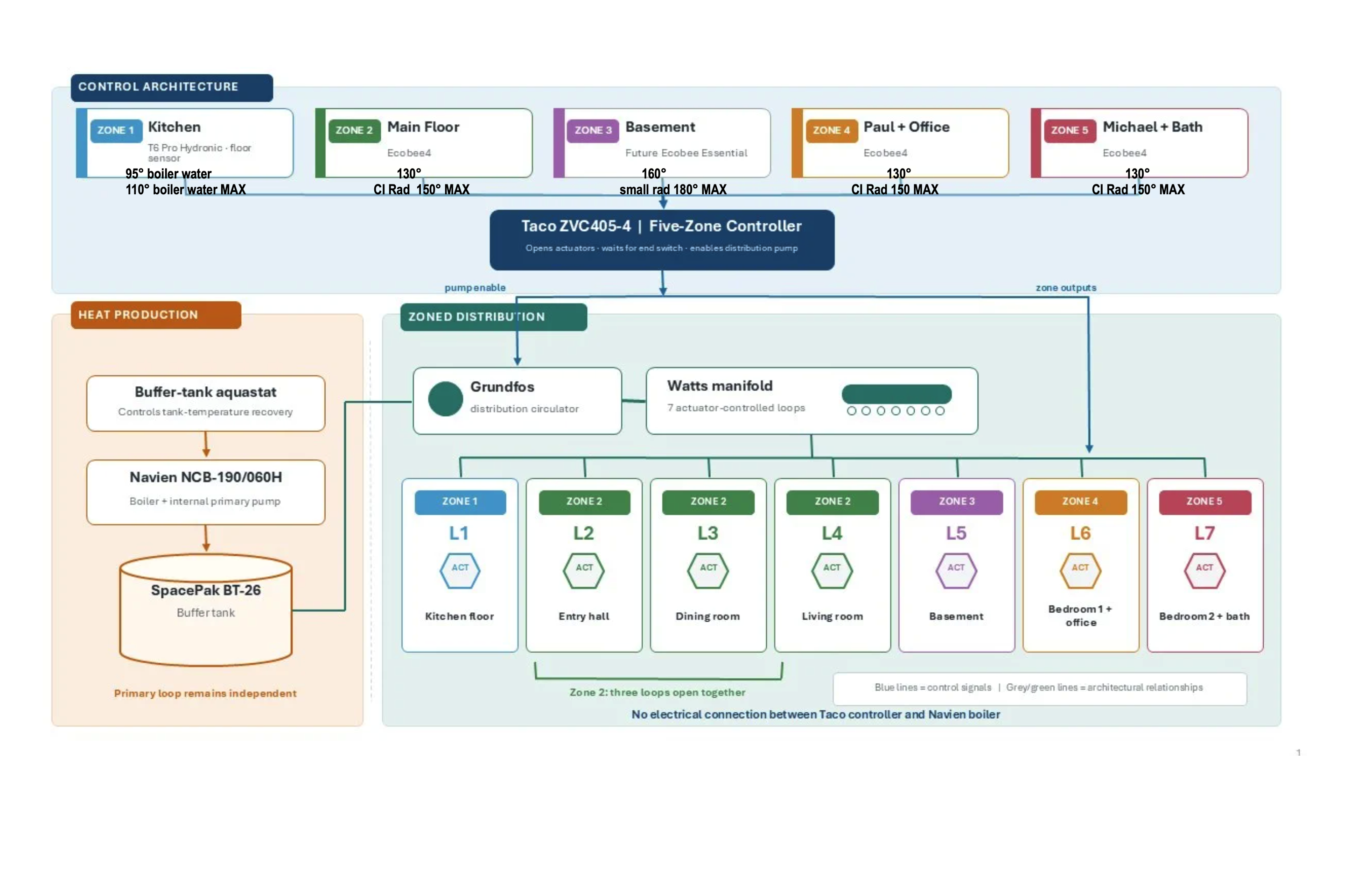
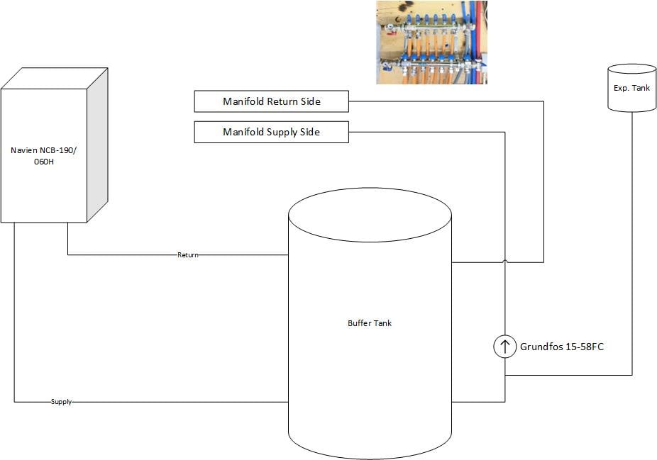
My housemate and I have different comfort needs in the bedrooms and we have a kitchen underfloor that currently runs with the rest of the heating meaning we only have a warm kitchen floor some of the time since the radiators don't run continuously. The design objective of this system was always to zone it off, so the system has a primary loop with an aquastat leading into a buffer tank and then a manifold that can take zone valves with a single grunfos circulator for the secondary distribution loop.
I'm having trouble getting a local contractor (Toronto, Ontario) to quote me either at all on the final zoning step of this work, or they quote an absurd amount. I was just quoted — (price removed due to rules) to supply and install 7 zone valves, one zone controller and one floor thermostat, do all required wiring and reconfiguring. They estimated — (price removed due to rules) in materials - when I know its only about $1500 Canadian for the 7 four wire actuators, one T6 Pro and a Taco Zone Controller. So unless i can find someone i'm likely going to need to do this work myself.
Before i do that I want to sanity check the whole end state design which is what this diagram shows. The primary and secondary loops have no control connection whatsoever - the aquastat just keeps the buffer tank at temperature (for winter I set it to 130 to take advantage of the modcon efficiencies) and the five thermostats just trigger the zone controller and run the grundfos system pump when at least one end switch activates. The new kitchen stat would be a floor model which i am planning to either try to grind out a little grout under a cabinet and then stuff the slab sensor in there.
So
- Anything insane about this design overall? One item i considered is whether the taco controller should also trigger the primary loop reheat call just to increase the responsiveness of dumping heat back into the buffer tank - but on slow heating like this I also am not sure if that would matter.
- Am I crazy to try to do this myself? (removing existing single t-stat from navien internal control, rewire pump, install and wire taco controller and zone valves, re-add tstats to zone controller). Is there a lot of configuration of the zone controller for a setup like this?
- Am I wrong to think that — (price removed due to rules) (Canadian) is overcharging for this work? Anyone know anyone in Toronto that might do this last bit of zoning?
Its a little house - and I know zoning is unusual - but I don't see how else i fix the floor problem - and at night when bedroom comfort is more important the two upstairs bedrooms are isolated from each other, and my housemate and I have temperature preferences about 4-5 degrees from one another. The basement is unfinished and also closed off all the time and the single small rad is just to keep it from freezing.
As always help from the experts - or referral to an expert I can pay! is always appreciated.
Comments
-
Well, please take the prices off — we don't quote those here on the Wall, for a variety of good reasons.
Now — that said, can you do it yourself? Can't really comment on that. It's not all that hard — but it does take time to read and thoroughly understand the instructions for the various gadgets involved and how they are hooked together. Your boiler and buffer tank work together, so the boiler firing should be controlled by the buffer tank temperature. No need for any other control on that. And the zone valves are controlled by the thermostats, and they in turn control the secondary main circulation pump (which with that many zones, should be a delta P controlled pump). You can stick a zone controller in there, and it does make the wiring a little more obvious — but strictly speaking you don't need it.
Br. Jamie, osb
Building superintendent/caretaker, 7200 sq. ft. historic house museum with dependencies in New England1 -
Thanks - blanked out the vendor pricing - left the retail equipment pricing in. I guess the part I was most worried about being a bad idea was that full decoupling of the heating side and the distribution side - I figure it means that the heat call for the buffer tank will be a little slow - but cast iron radiators and underfloor staple up aren't exactly fast either.
I also seem to see lots of strategies for controlling the heat call for a staple up radiant floor too - like just sensing the room air temp (but in my case the floor isn't really the emitter for the air on that floor), slab sensors of course but then they say you can overheat the room - or a combined air and slab sensor so you can kill the heat if the air gets too warm but to the t-call on the slab temperature.
This has all been a lot of learning - and i'd rather not do it myself, but the prices i'm getting do seem to be a little divorced from what I think is the amount of work involved and the cost of the equipment involved - but i could be mistaken on that too.
0 -
pay a qualified contractor what they want. Learn along the way.
Not knowing
Going on the internet
Cutting corners, 90% of the time that costs more, especially in comfort1 -
We have seen some very nice, code compliant DIYer systems here over the last 30 years! It really comes down to you, not us :)
The buffer temperature is maintained by the ODR settings. Some day the buffer may be 110, other days it ramps to 130.
The way you pipe the buffer is critical to best efficiency.
Your most precious hydronic water is the water you just paid to heat. So that should go direct to load. Not through a buffer, closely spaced tees, around a primary loop, etc, direct to the load. Two and 3 pipe buffer tanks work best.
Use a delta P pump and just plug it into a hot receptacle. Then it can run it's exercise function during off season.
Comfort to most people is judged by air temperature. As much as we try to use floor sensors, occupancy and other internal gains can throw it for a loop. Floor sensing along with air temp limit can work. With a perfectly dialed in ODR the system should run non stop, and not need thermostats :)
Mixing emitters can get tricky CI rads on the same loop with low mass fin tube or panel rads is not always a good idea.
The lower the mass the quicker it will respond to setbacks. Radiant floors, even staple up will flywheel for an hour or more. If you add mass, like tile, you icrease the flywheel.
Be realistic on you room temperature variations. A few degrees okay, don't expect 10- 15° differences.
 Bob "hot rod" Rohr
trainer for Caleffi NA
Living the hydronic dream1 -
Prices are outrageous ever since Covid. I retired over 7 years ago and did a decent amount of estimating back then. I couldn't even attempt to guess the price of a job now.
Are some contractors greedy? Yup
But I was one myself.
If you add up the cost of truck, tools, lability insurance, workmen's comp insurance, truck insurance, labor cost, training costs, licenses and permits it all adds up. And I am sure there is lots more I have forgotten. And if the contractor doesn't make a profit he will be shortly out of business. It is very tough being a contractor.
A homeowner doing his/her own work only has 2 things on the list to purchase and that would be tools and permits.
1 -
@Ekkridon said: "The new kitchen stat would be a floor model which i am planning to either try to grind out a little grout under a cabinet and then stuff the slab sensor in there."
Is there access to the tile floor from below? putting the sensor under a cabinet where the floor temperature will not be a true representative of the open space floor may not offer the accuracy you are looking for. Router from below the get to the tile from below will offere you a better temperature reading. (but this may actually be splitting hairs and unnecessary. just some ramblings.)
The next thing is to look at how to get different water temperatures from the same buffer tank, and that is easy
You may need to repipe for different temperatures.

However if the only real problem is the second floor cast iron radiators making the bedroom too hot or not hot enough, then you may be able to do this for a lot less with a thermostatic radiator valve. Set the thermostat for the hotter bedroom temperature as needed and then adjust the cooler bedroom TRV to the desired temperature and you have what you are looking for without all the expensive controls and time spent designing and wiring.
This assumes that the system is working fin now and only the one bedroom needs to be lowered.
Edward Young Retired
After you make that expensive repair and you still have the same problem, What will you check next?
1 -
Thank you so much to everyone who has replied. Both in concrete suggestions for modification and (sincerely) for helping me understand the drivers of costs for contractors to do this work. I certainly recognize that there are real costs to that work, and that the expertise that an experienced hydronics pro is worth real money and can save me time and frustration in the future.
Here is what i'm taking away from this thread I think. I have been pretty successful running the whole loop at 130 - in that even though that is significantly below what I imagine the design temperature was for the CI rads in the house, we have managed even through some very cold days to keep things warm - even if we had some room to room variation that we are hoping to smooth a bit through zoning. I can see that i'm going to end up running the kitchen floor a little bit hot, but without a contractor doing the work I'm trying very hard to not make any piping changes (so adding mixing is something i'd like to avoid).
The primary loop is currently the combi boiler to the buffer tank via a non ODR aquastat. So i've put on my todo list to replace that aquastat (Emerson of some description) with an ODR supporting model. The only annoying thing is that the dry well in the buffer tank is too small to accommodate the sensor for a Tekmar 256, so my plan would be to strap it on to the piping where water leaves the buffer tank and enters the secondary loop - which i figure if I swap the existing Grundfos UPS15-58FC for a Grundfos ALPHA 15-58F that avoids needing to do pump control and instead just have it run the secondary loop on its own that should keep that bit of output copper pretty reflective of the temperature inside the buffer tank. This should be straightforward since by the specs its a drop in replacement and i have isolation valves on both sides of the pump.
Then that means the zone controller is only doing actuators and not pumps and with ODR I don't need to do my seasonal adjustment in the buffer tank temperature (which I inevitably forget to do and run a bunch of the spring keeping the buffer tank at 130 unnecessarily). It also seems this would allow me to phase some of this work for myself - since I could replace the pump and add the ODR any time in advance of installing the zone controller - which is friendlier for a homeowner that has to attend to my 'real' job which is in IT.
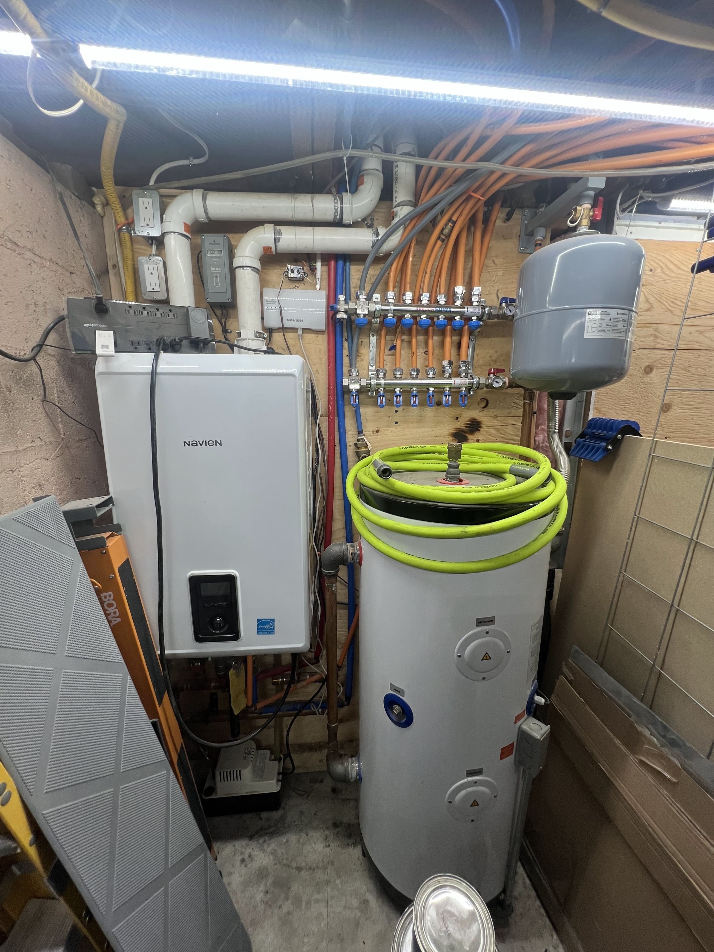
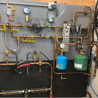
Just for funzies - here is the setup as it stands today (ignore the power bar, the boiler circuit needed a new breaker and i haven't moved all the electrical back yet) - the circulator is hiding to the right of the buffer tank. Again thank you everyone for all the input and education!
 0
0 -
Look in the manual, your boiler should have ODR and a sensor included. Just run the buffer off ODR, maybe 130 as the highest temperature at design condition. CNT 3 connection
I think the tank could be controlled via a sensor connected to CNT 1 . You should not need another setpoint control to run this system. Check with Navian about that sensor connection.
Some boilers ship with an additional sensor, to be used in an indirect tank, do you have a spare sensor?

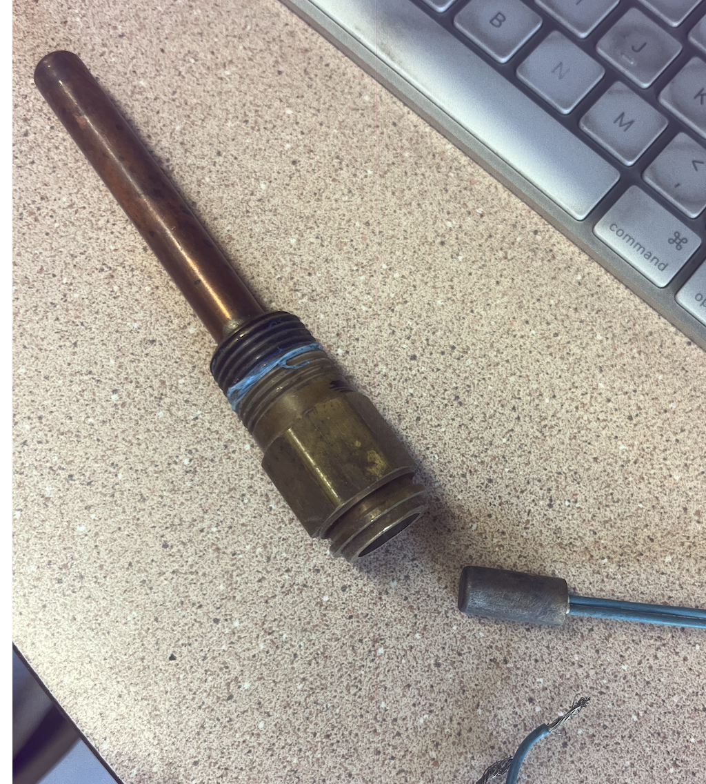
You have a spare port into the tank to add a sensor well. Maybe 1/2 or 3/4 NPT size.
A 1/2" inside diameter well shown below gives you sensor flexibility
Or remove the hand hole cover and fasten the sensor against the metal tenk surface with some insulation to hold it tightly against the tank..
 Bob "hot rod" Rohr
trainer for Caleffi NA
Living the hydronic dream 1
1 -
I am looking at your message you sent and believe that you may have incorrect radiator piping
This was your message regarding a TRV as the simplest way to solve your problem
@Ekkridon asked: The radiator in the room that gets too hot (annoyingly my bedroom) is on a shared loop with the adjacent upstairs office - and i've never been sure if a TRV just closes - or if it just bypasses the radiator and passes the water along the loop.
This was my answer: "It does not bypass. it closes. a cast Iron radiator should not be in series with another Cast Iron radiator. They should be on some type of parallel piping arrangement, be it reverse return of direct return.
regarding the boiler room pic. are all your "loops/zones" included on that manifold?
Next observation…. if you use a motorized zone valve to shut down that "Too Hot" loop with radiators in series. you will end up with the same result. shut off the bedroom that is too hot with a TRV or an electric valve, you will also shut off the office. So your electric valve solution does not give you the result you are looking for. So a repipe to bypass to the office will be needed with what ever valve you choose to close off the bedroom that is too hot.
Electricity does not make water flow differently. But valves do."
one additional note: there are some Euro TRVs that do bypass but they need to be piped in the system properly. CI rads are not usually connected that way
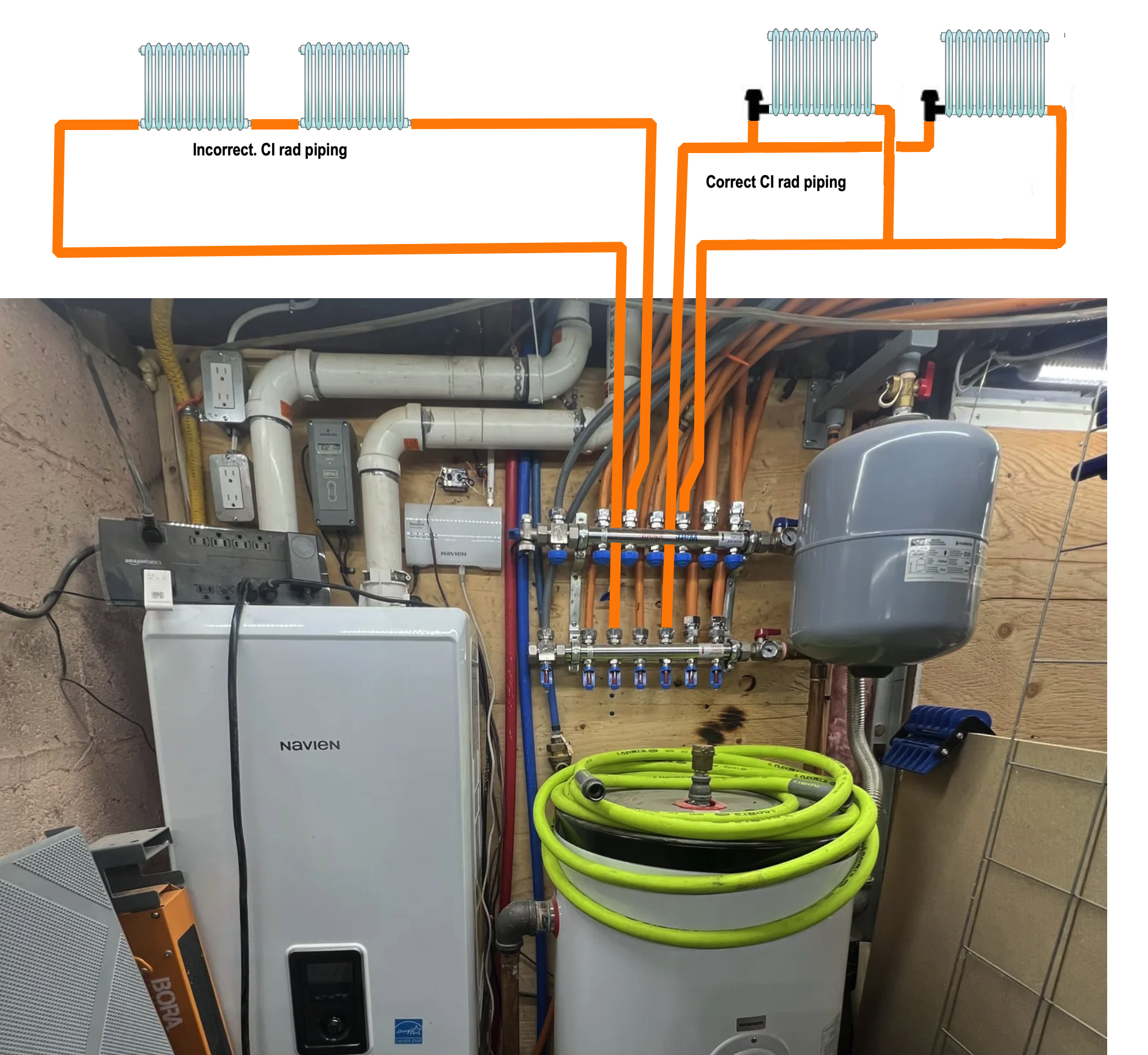
Were these CI rads always there? did you do the repiping to make them a series loop? Was this professionally done? If done professionally, don't use that plumber/contractor any more
Edward Young Retired
After you make that expensive repair and you still have the same problem, What will you check next?
0 -
You know what - you are absolutely right. And it may very well be piped correctly then. I was expecting (as with everywhere else in the house) a loop per radiator - and when we replaced the iron piping in the basement that feeds all the loops (because it was lousy with asbestos) the two loops upstairs each only had a single feed and return - it didn't even occur to me that they might tee off inside the floor of the upper story in a way that would pipe them in parallel relative to the feed and return!
I suppose the way to test is to shut the intake right down on one of them and trigger a heat call - see if the second rad gets hot anyway? Any better way to know for sure?
The only repiping i've contracted in this house was the installation of the combi boiler, buffer, manifold and kitchen staple up (always with a plan to get to a zoning place eventually), and then the removal of that asbestos coated pipe before we even moved in. So it might be done correctly as you've diagrammed - and that would make a TRV an easier solution for the one-room-too-hot problem. I'll have to do some testing and ponder if that is a better way to go - its certainly less expensive!
I still think zoning is the only way to get my kitchen floor loop to run more often and keep that floor toasty all the time in winter - but there might be a simpler answer for the bedroom loops than I was thinking about. Thanks Ed!
0 -
That is what you get from over 40 years of experience. My minds eye sees thru the floors walls and ceiling becasue I have seen this stuff when the house is opened up for repairs. As a person not familliar with 50+ ways to do stuff, your assumptions come from a different perspective. That is what we do this for. to give you the benefit of our experience.
With more accurate info, we can work together to get your system to work better. You may be looking at a ZVC405 and zone valves to get what you want. this way I can help. you may even end up with one TRV on your radiator when everything else is done.
Lets first fighre out what you acrually have. Verify the loop on the right is what you have by testing to see if one radiator gets hot while the other radiator is off. Once we know that, then we can draw the piping layout for all the other zones.
Edward Young Retired
After you make that expensive repair and you still have the same problem, What will you check next?
0 -
I would like to understand your existing piping. I cant tell where the circulators aare located from your photo but I have this basic boiler room piping that does not include DHW piping
Design A
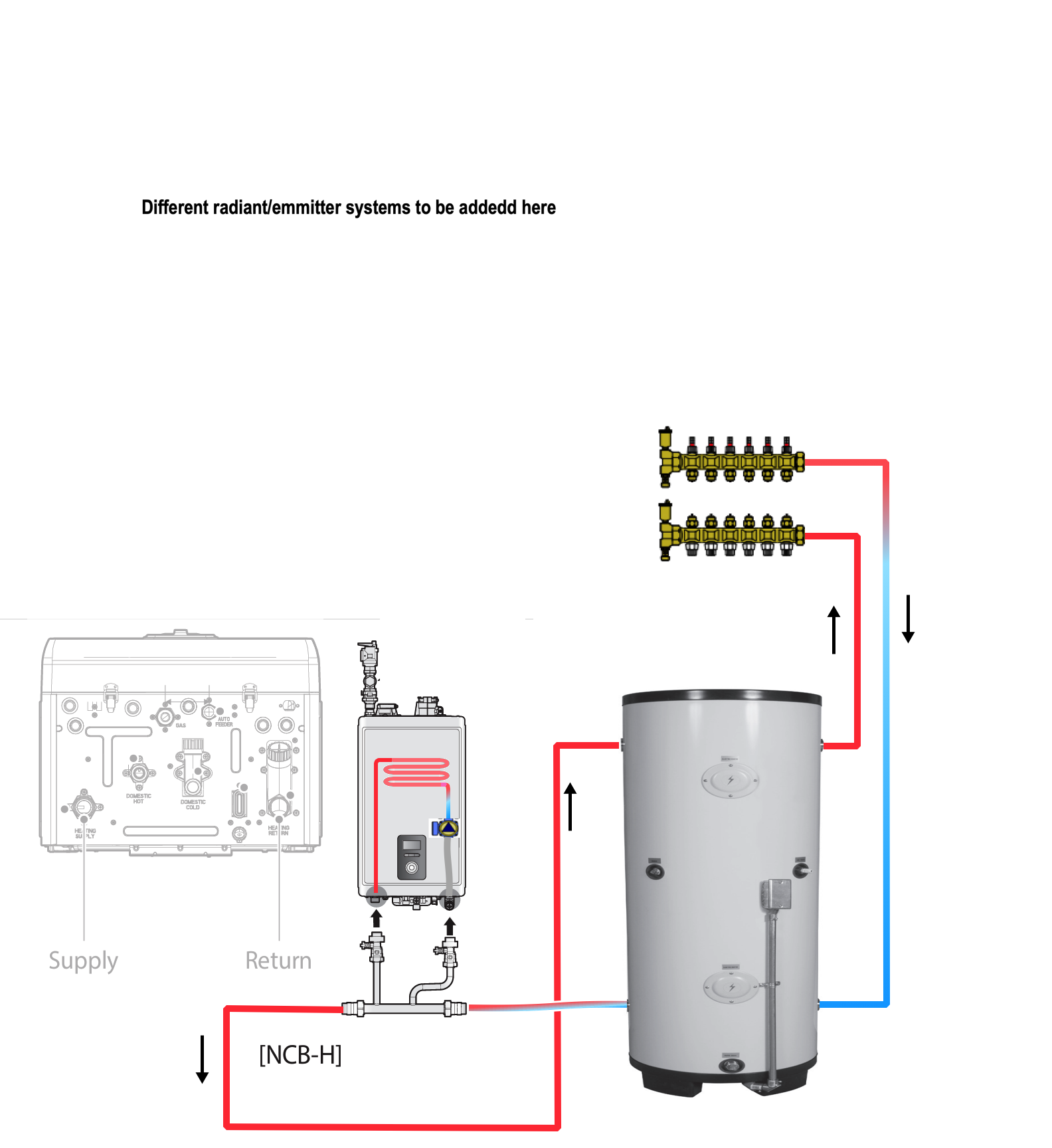
If this is correct then you can confirm. There is a second possibility where the internal circulator of the Navian is employed to the Buffer Tank like the next illustration:
Design B
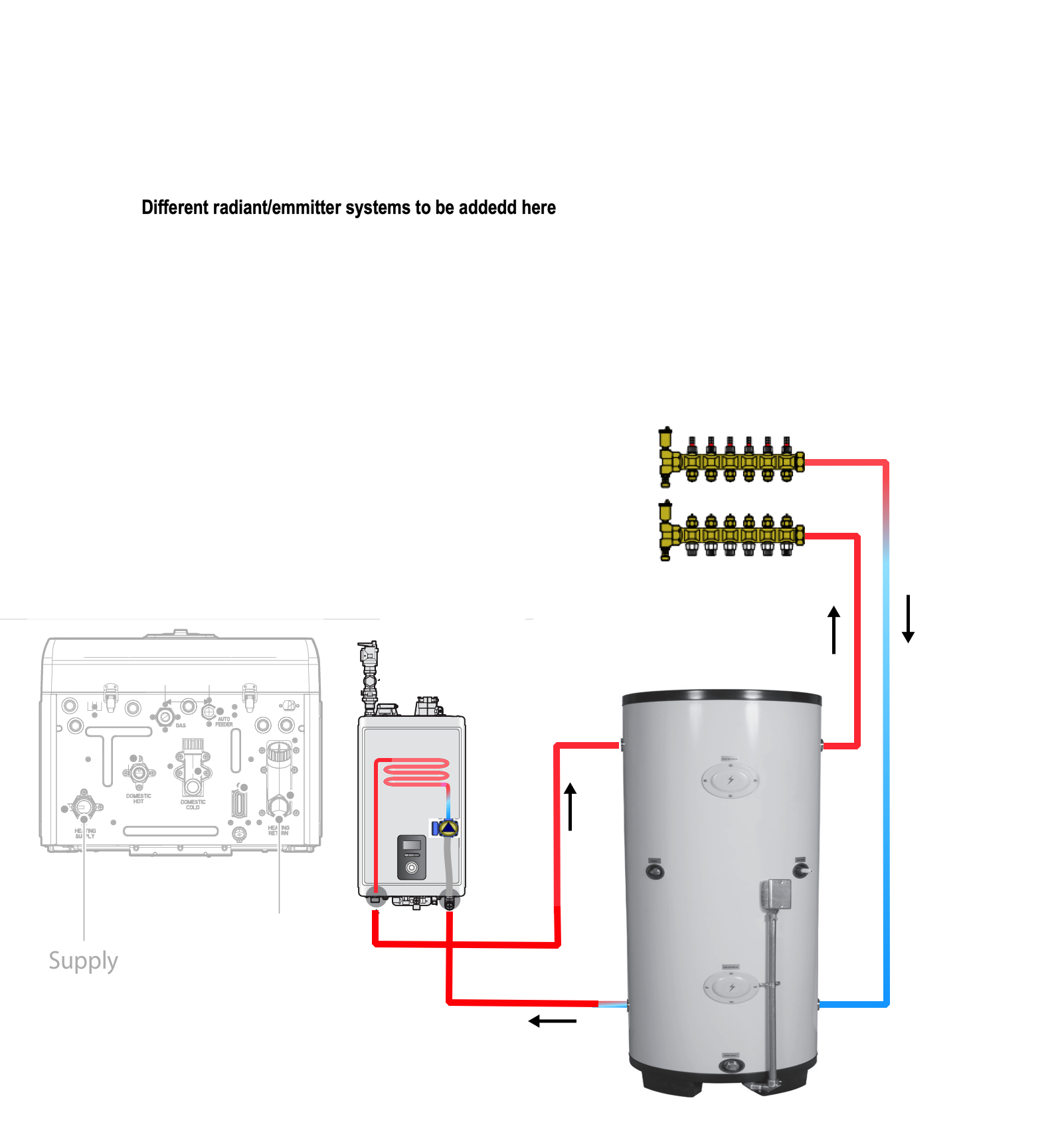
Let me know what you have?
From there you may have the answer to how the radiators are connected, then we can build the top portion of your diagram. Once we have the proper piping design, we can design the electrical controls.
Also, let me know if you have any of the components yet like the ZVC and if you opened it, so it can't be returned. There may be a better control stragety but I can work with what you already own.
Edward Young Retired
After you make that expensive repair and you still have the same problem, What will you check next?
0 -
Your B diagram is what I have - the SH outputs of the navien aren't joined - its copper from the hot output to the buffer tank hot input then a return from the cold port on the buffer tank back to the navien. Then the circulator is piped from the bottom port of the buffer tank on the other side (which is marked blue?) piped with copper into the supply side of the manifold which then returns with some flex pipe back to the top (red) port of the buffer tank.
Right now my revised plan would be to install the actuators - which i understand just go on under the blue caps on the manifold, connect them an all the t-stats to a new zone controller and replace the pump with an ECM model per hot_rod's advice - and then I won't actually trigger the circulator with the zone controller but just let it go. Again the zoning main result is that the kitchen floor (the lighter grey/translucent output that is an add-on to the manifold on the left runs more often than the other zones to keep the kitchen floor warm and then potentially keeping the bedrooms more balanced (which are the larger pex on the right since each pipe serves 2 CI rads). I haven't had a chance to do the piping test yet.
My bedrooms' heat difference may be in part because i have a relatively powerful computer running in there 24/7 - draws about 270W continuous while i'm using it and about 150W when i'm not. Its also south facing and unshaded where the rear bedroom is north facing and has a big oak tree shading it. The bedrooms seem to maintain some separation temperature wise which might be becuase both bedrooms closets separate the rooms, and those closets are pretty full these days. In any event it still means in winter my room needs less heat.
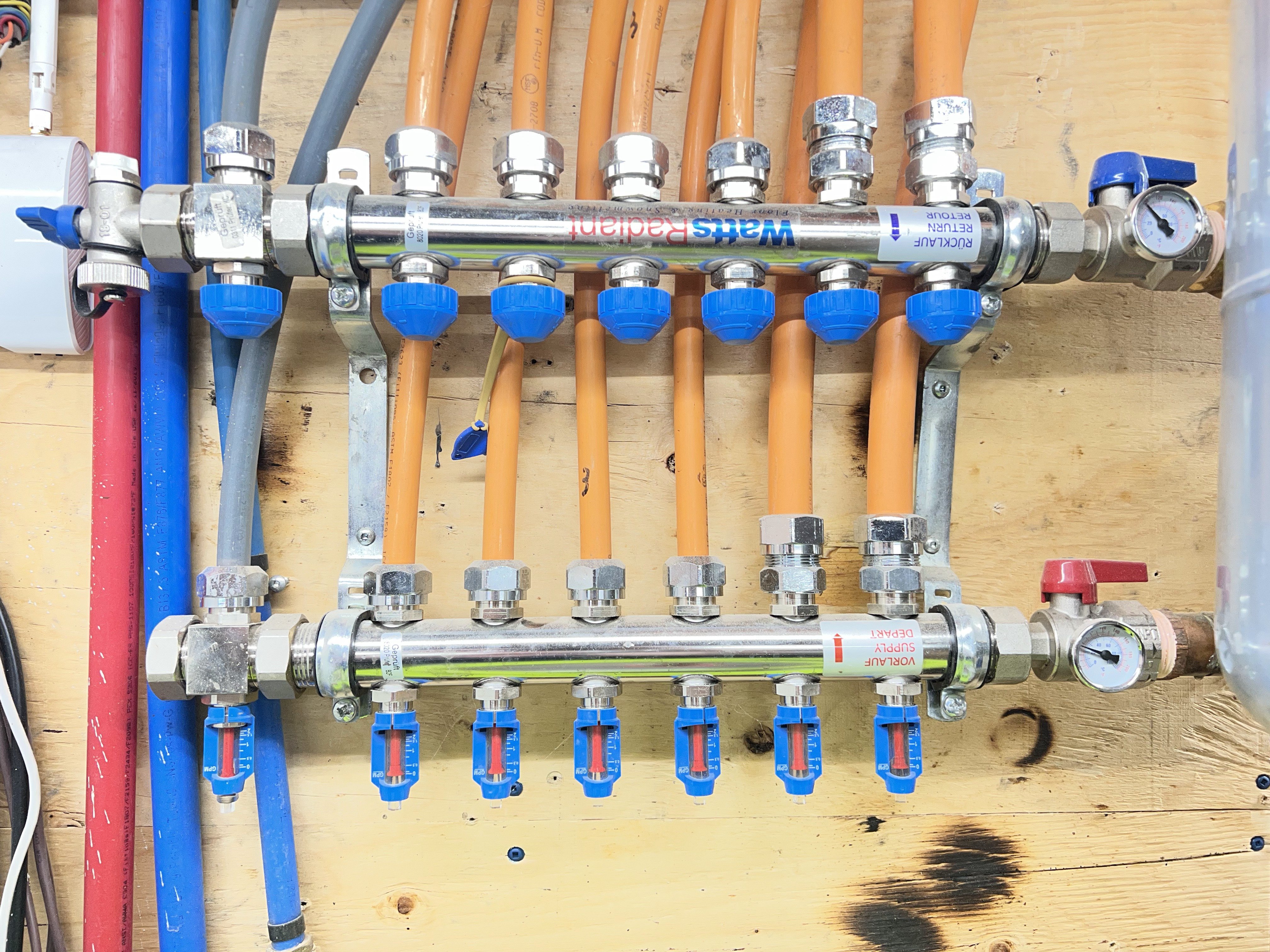
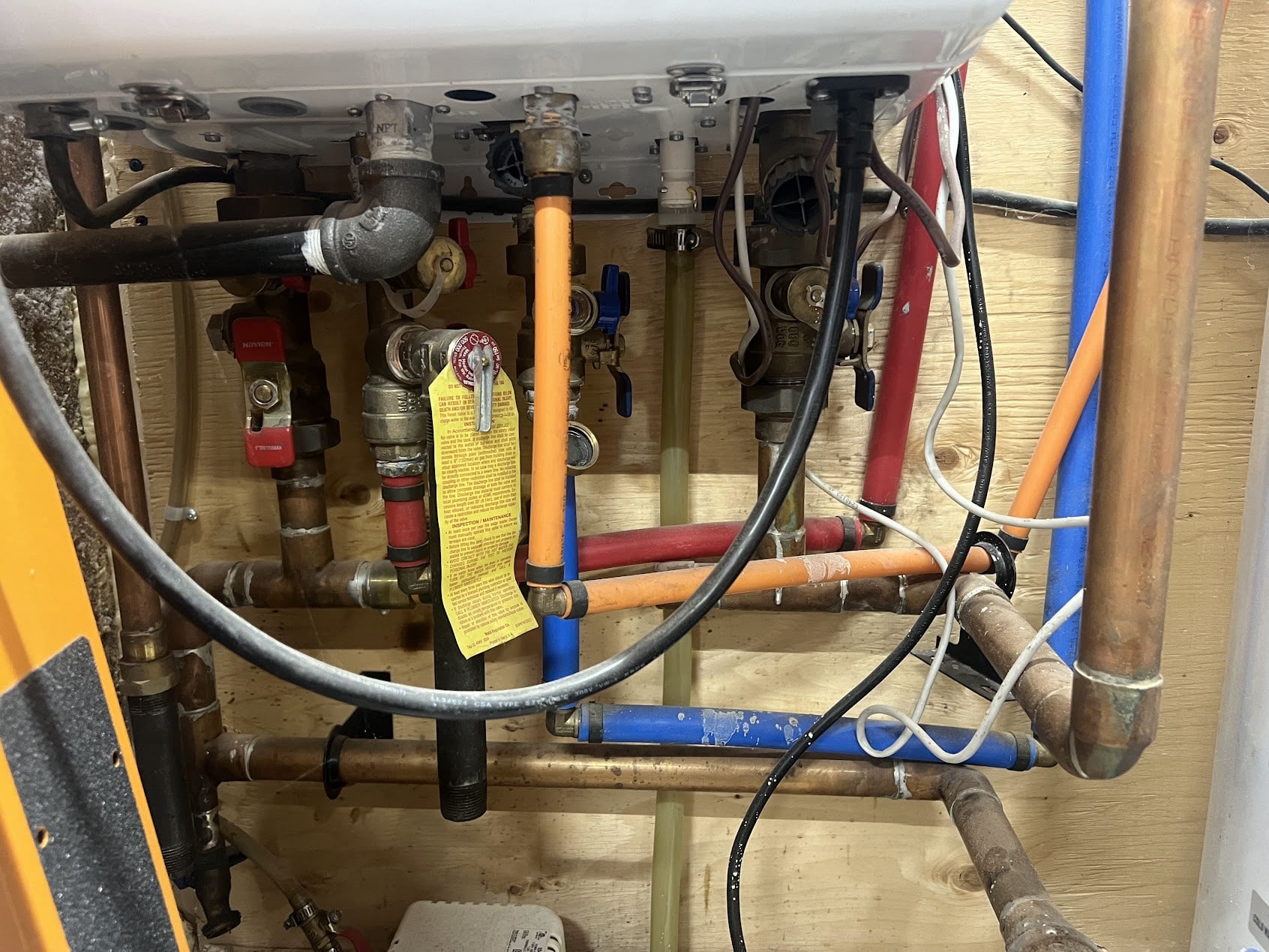
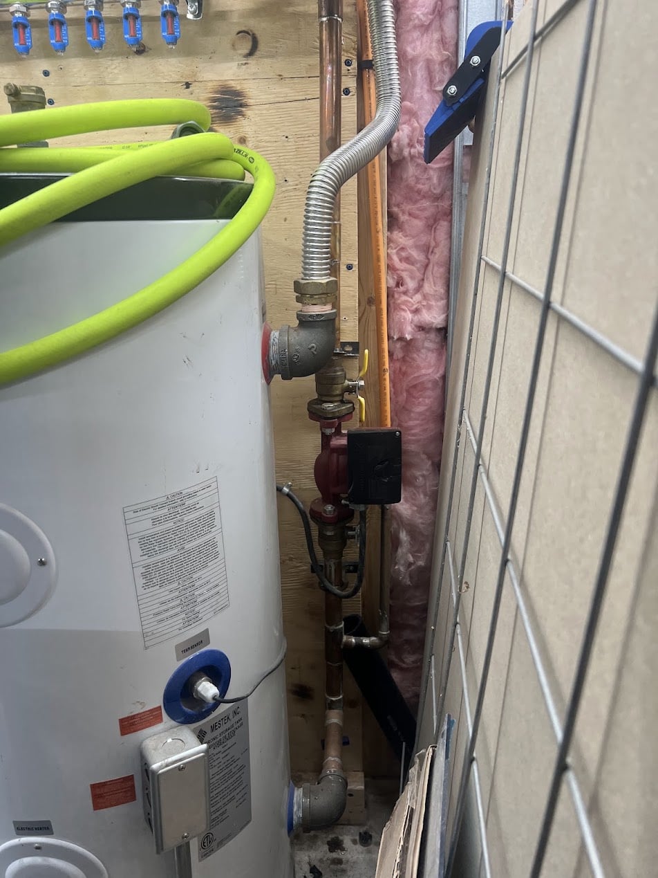 0
0 -
Looks like close spaced tees under the boiler?
If so the boiler needs a pump, and the loop needs a pump. Plus the zone pump off the buffer, which you have.
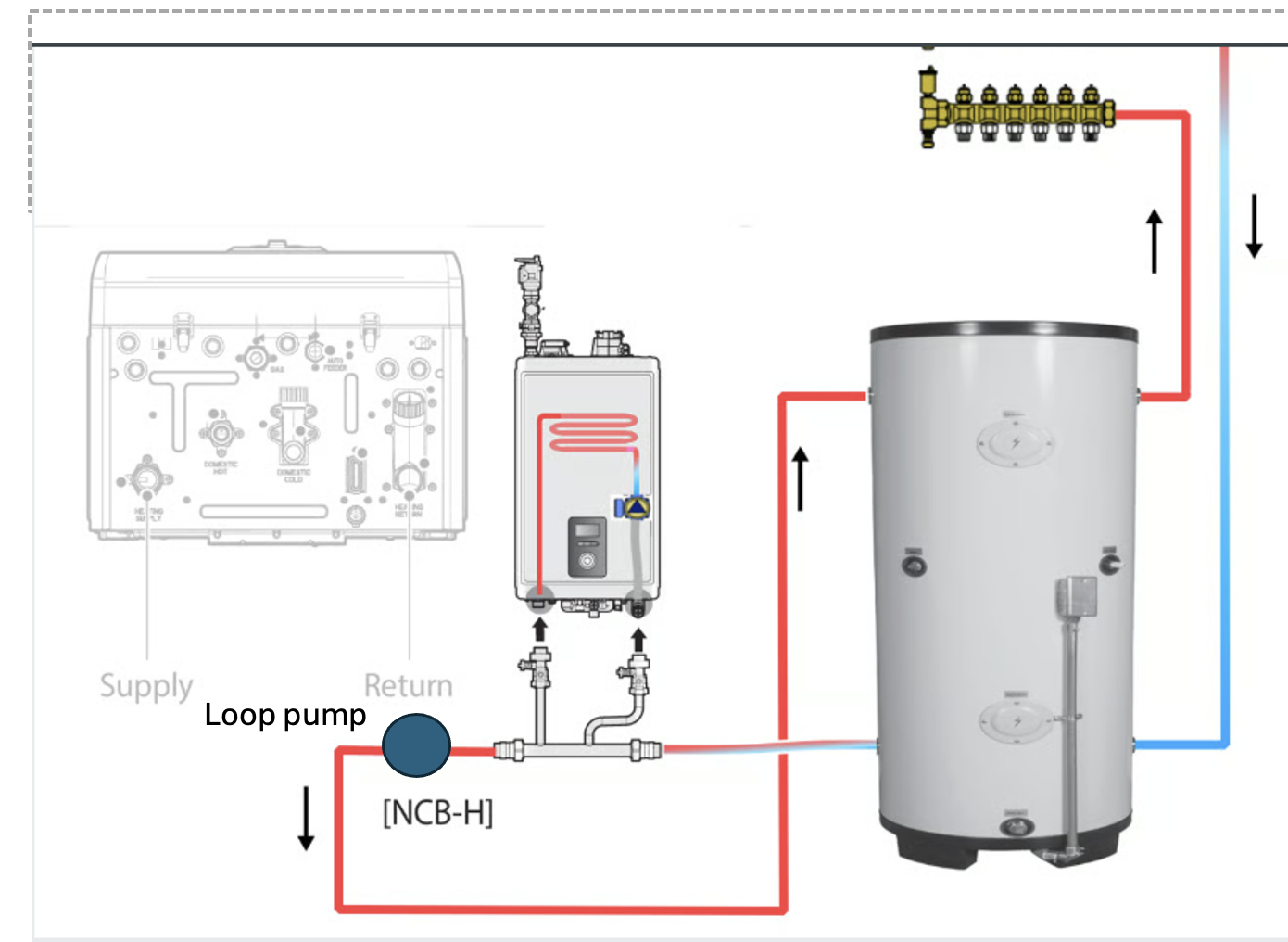 Bob "hot rod" Rohr
trainer for Caleffi NA
Living the hydronic dream0 -
No - I know that photo is from a misleading angle - but is isn't a connected bit - the hot and cold side are independent and it uses the internal circulator inside the navien to run the primary loop. If you look just at the the condensate drain line the copper is capped and doesn't extend and connect. Here is a photo with a better? angle. Whats weird is that looking at your bottom diagram i would expect the right hand one to be the return - but thats the one that gets hotter when i have it run a heat call to the buffer tank
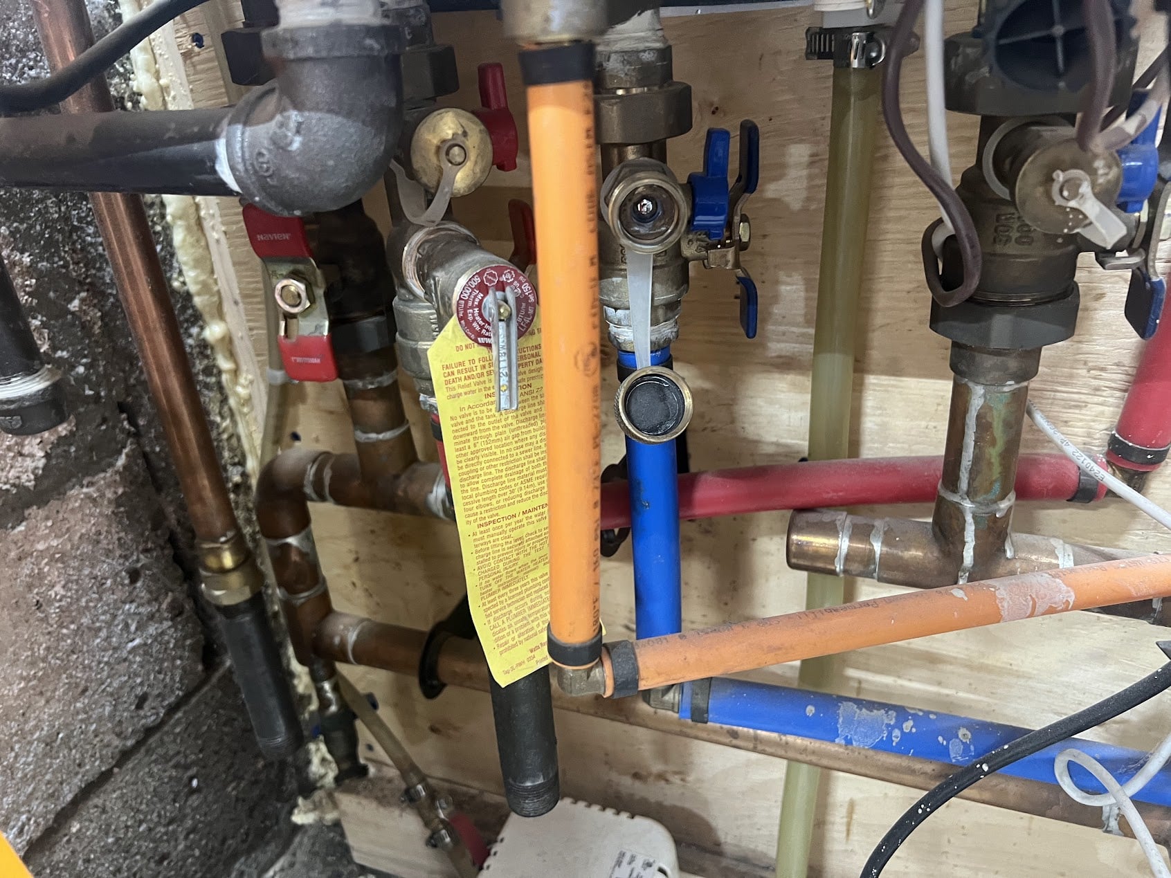 0
0 -
looks like someone changed a closely spaced tee below the boiler?
Usually all the connections are labeled on the bottom of the boiler, supply, return domestic in and out? Also the pump will have an arrow on it for direction of flow. The hot from boiler should go to top of tank.
If the boiler, with an internal pump, just goes to the buffer then you have that tank as the hydraulic separator function, so all looks good.
Is the expansion tank flex connected to the top buffer port? Where does the radiant pull from the tank? Connections on the back?
A drawing might be better than pics with so much hidden from view. But while not ideal piping, sounds like it works.
Bob "hot rod" Rohr
trainer for Caleffi NA
Living the hydronic dream0 -
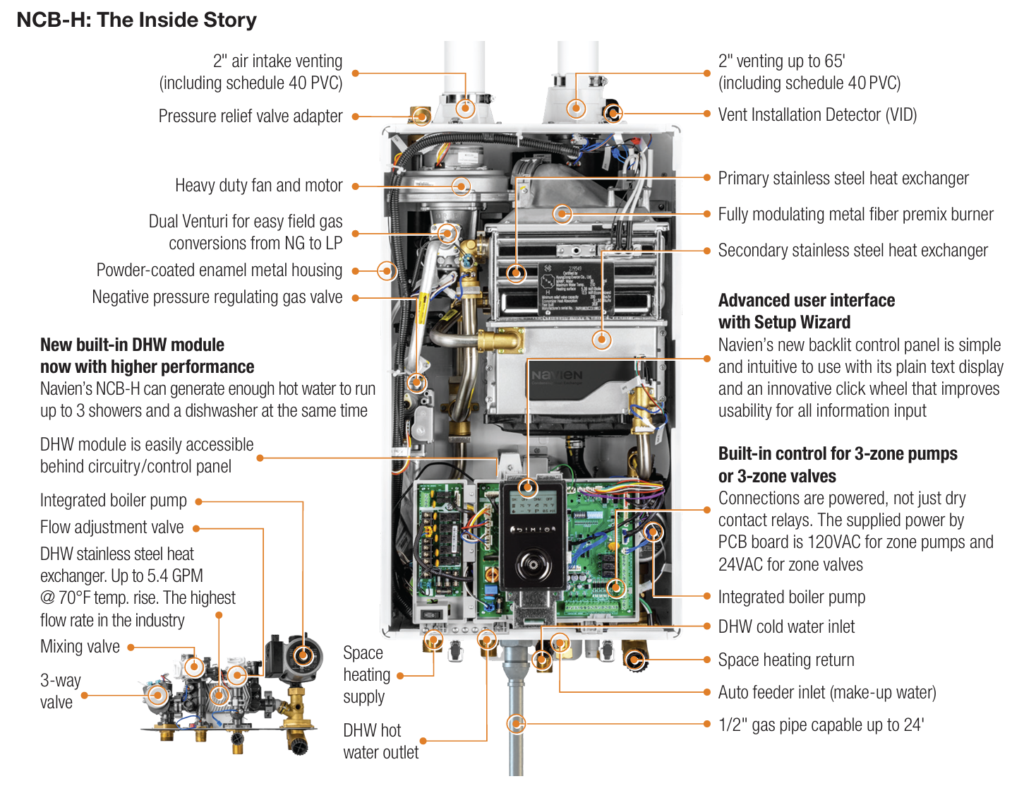
Please excuse my diagramming skills. It does look like a set of closely spaced tees was hacked apart. Weirdly the horizontal end of the supply one is converted to pex and then has a plug in it and the return horizontal end has a copper cap. Only two contractors have ever worked on this system - the original installers who installed the boiler, buffer, expansion,circulator and a copper manifold and then the company that put up my staple-up for my kitchen who replaced the manifold with this type at my request (knowing that it would be easier to put actuators on later).
I've confirmed all the flow directions in the manual for the boiler
 0
0 -
The combi type mod cons have a pump in or under them, so you don't need the closely spaced tees when you pipe to a buffer. if fact it may not work well with closely spaced tees, as someone maybe discovered?
Bob "hot rod" Rohr
trainer for Caleffi NA
Living the hydronic dream0 -
So I finally got my parts in and started working on this today. Today's work was pretty simple - running the thermostat wire for a new T6 Pro with a slab sensor. I (thanks to suggestions on here) used an oscillating saw to cut a small slot up through the subfloor until i found the bottom of the tile thinset. I'm going to thermal epoxy a bit of 3/8" soft coppper tubing with a slight bend in it to the bottom of the thinset to act as a thermal well for the T6 slab sensor and then fill the rest of the slot with silicone so I can replace the sensor if it ever fails. The thermostat itself is mounted under the cabinets in the kitchen to control the floor temp.
Plan is to run it in F mode - and then get to some kind of sustainable min and max that doesn't cook the rest of the house.
Another change based on the kind advice on here is I got Grundfos Alpha 15-58 FR (I needed the FR for the bolt pattern) and my plan is to swap the pumps - initially letting the navien keep powering the pump as needed as the rest of the work gets done.
If i understand your advice above @hot_rod are you saying I should wire the delta-P pump in constant pressure mode right to an appliance line cord and run it 100% of the time even if most of that time it would be dead-headed against the manifold when no zones are calling? I just want to make sure i'm understanding correctly. I bought a second line cord to power the zone controller too.
My supplier accidentally gave me 2 wire zone actuators but we are swapping them, even if in this setup i don't strictly need the end switch - its nice for the zone controller to actually have the indicator of zones being open - and it gives me the option to trigger the pump from the controller if i terribly misinterpreted @hot_rod's advice above.
Next is to do a rather miserable thermostat wire fishing job from the upstairs to the basement for the bedroom thermostats - but after that the wiring should be all well within my normal skillset.
Thanks again to everyone who helped - especially @hot_rod and @EdTheHeaterMan .
0 -
—
"If i understand your advice above @hot_rod are you saying I should wire the delta-P pump in constant pressure mode right to an appliance line cord and run it 100% of the time even if most of that time it would be dead-headed against the manifold when no zones are calling? I just want to make sure i'm understanding correctly. I bought a second line cord to power the zone controller too.My supplier accidentally gave me 2 wire zone actuators but we are swapping them, even if in this setup i don't strictly need the end switch - its nice for the zone controller to actually have the indicator of zones being open - and it gives me the option to trigger the pump from the controller if i terribly misinterpreted @hot_rod's advice above."
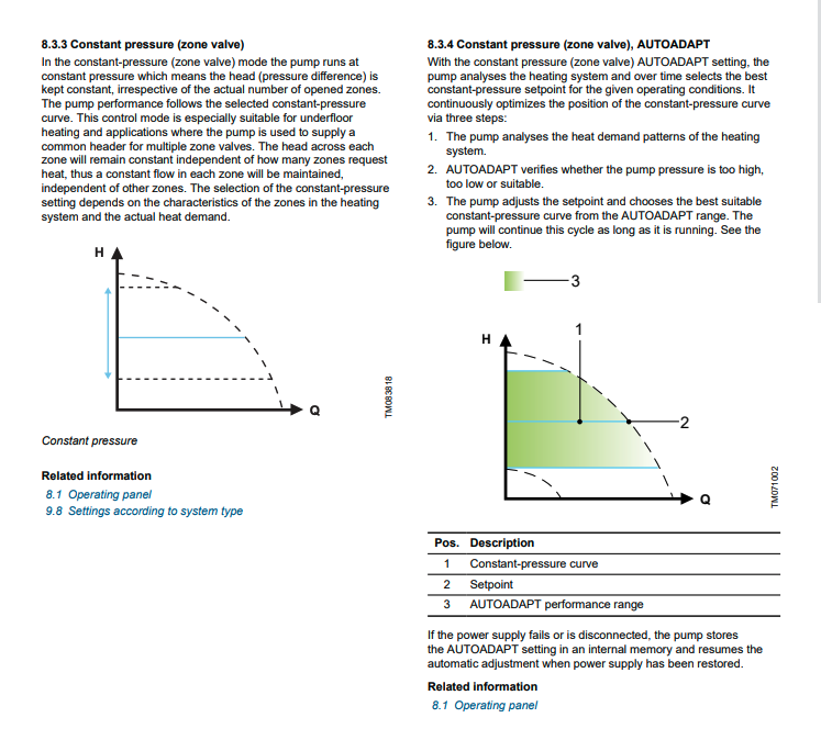
—You don't really dead head a delta P circ when all zones are off. It goes into an idle mode, about 7W. So it is spinning ever so slow. It needs to be spinning so it can sense when a ZV opens.
That being said, you would not need to have the pump come on with an end switch contact, just plug it in and forget it.
Or if you run it through a zone relay box in addition to indicator lights, you get an exercise function that starts the pump every 72 hours, to prevent sticking.
However the newest Alpha address that with the Automatic Operation anti lock function. So constant pressure or with Auto Adapt. The auto adapt takes time to learn use patterns, so be patient if you use that function.

 Bob "hot rod" Rohr
trainer for Caleffi NA
Living the hydronic dream0 -
Pump swap is done. Had a little trouble getting it to purge, but I think low pressure in my system overall was impacting it (the Navien fill valve doesn't seem to be doing its job). So i just upped the pressure by adding water into the buffer tank up to 25psi (hot) and that seemed to make the purge cycle more effective.
Its still being run by the navien during a heat call - next I need to install the Taco zone controller and I have two more thermostat wire runs to pull.
I'm also DIYing a thermowell for the slab sensor for the radiant floor - JB-Weld hi-temp epoxying a bit of soft copper tubing with a closed end against the underside of the thinset and i'll jam the slab sensor up into it in case I ever need to replace the sensor.
Its honestly all going ok - aside from my boiler board not having room for the taco - I did not understand just how big that controller is - but I have another spot close enough (I hope) to mount it so the zone actuator wires can reach the manifold.
0




Categories
- All Categories
- 87.8K THE MAIN WALL
- 3.3K A-C, Heat Pumps & Refrigeration
- 60 Biomass
- 430 Carbon Monoxide Awareness
- 133 Chimneys & Flues
- 2.2K Domestic Hot Water
- 6K Gas Heating
- 124 Geothermal
- 170 Indoor-Air Quality
- 3.9K Oil Heating
- 79 Pipe Deterioration
- 1.1K Plumbing
- 6.7K Radiant Heating
- 397 Solar
- 16.1K Strictly Steam
- 3.5K Thermostats and Controls
- 56 Water Quality
- 51 Industry Classes
- 51 Job Opportunities
- 18 Recall Announcements