Hydronic Heating and Cooling on a Ship

I'm the chief engineer of a small cruise ship. I regularly get complaints about a gurgling sound coming from our heating and cooling system, and I'm finally in a place were I can have a good hard look at the system.
The boat was built in 91' in RI. It is a two pipe system with about 50 fan coil units in 2 zones with direct returns. From what I can tell the is nothing to balance the system so the way they got flow was to brute force it. There is a 2hp 3 phase pump pushing about 100GPM and has a 20psi pressure differential. My total system height is 21' with the pump, boiler, chiller, and compression tank all at the bottom. There is also no air separator installed just a couple bleed vents at some high spots. I'm getting a 4 degree F temperature difference right now.
The whole system is about 100 gallons of 50% Propylene glycol so it can be shut down in the Seattle winter. The boiler is 60kw and the chiller is 25 ton. They are plumbed in parallel on the outlet side of the pump so we open the valves of one and close the other to switch.
What I think I need to do is a number of things. First I want to reduce my pump to 2/3 speed. I think this should lower my GPM to about 66, and lower my pressure difference to 8.8psi. Then I can set my cold fill temp to 13 for my 21' of rise giving me a max cold pressure of 22 well below my 30psi max.
With the slower total flow I think I'm going to have to add metering devices to all of my fan coil units to make sure I have flow to my furthest.
Next I want to move my boiler to the pumps suction side with an air separator between the outlet of the boiler and the inlet of the pump. Then I can either add a compression tank to the air sep, or put a bleed valve on it and add a diaphragm tank between it and the pump.
My goals are to reduce noise, and prevent pipe corrosion. Any efficiency gain is always a plus.
Comments
-
glycol mixtures hold on to air a lot better than plain water so you really need to have microbubble air separation.
if you have zone valves on each fan coil then balancing valves are maybe less important because the zones with more flow will satisfy first and shut off directing more flow to the zones with less flow. ideally you will balance it somewhat but zoning makes it less critical.
the air will cause you a lot more problems with circulation than not having balancing valves. ideally the piping would have been sized to provide rough balancing.
 1
1 -
Any idea on the size or btu load of the fan coils?
Call it 1.5 gpm/ or 15,000 btu/hr
50 X1.5 gpm = 75 gpm
Fill pressure 21' X .433 = 9 psi static fill. Add 5 psi for some positive pressure up top, so 14 psi fill.
The 50% glycol will cost you some pumping power. I doubt you need 2 hp? The piping and coil pressure drop is the key.
But the chiller pressure drop may be a high number?
You definitely need an air sep, and you need to pump away from the expansion vessel, or air will haunt you till times end. A diaphram type expansion tank will be 1/3 the size of a compression style tank. So boiler supply air sep, with tnk connected, then circ pump.
A automatic PIV pressure independent valve works great on that many coils. You buy the gpm each coil needs.
You will spend days trying to manually balancing 50 coils.
Ideally a delta P circulator that modulates as valves or coils come and go.
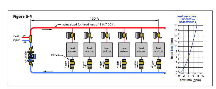
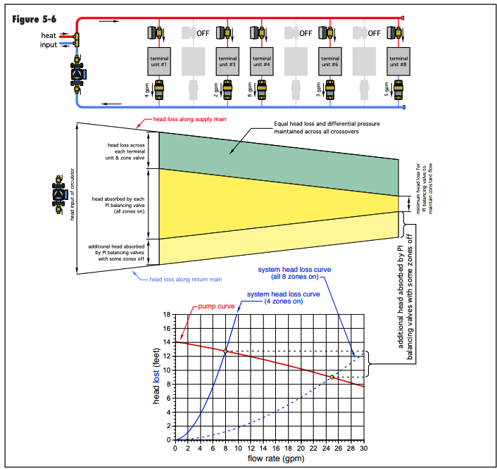
An ECM delta P circ, Grundfos Magna, could cut pumping power down by 50% maybe more.
Bob "hot rod" Rohr
trainer for Caleffi NA
Living the hydronic dream0 -
Good to know about the microbubble separator.
There is no flow control at all right now. The pump runs 24/7 and fluid flows through everything all the time. So I'm worried about starving my furthest units if I slow things down. The only control is for the blower fans. The two zones are parallel runs down either side of the ship with roughly the same load. There is no zone control.
I don't know many details of the fan coil units. Some of them look like re purposed evaporators.
I'm sure I don't need the 2 hp pump but it's the one I have. I was thinking about putting a VFD on it to slow it down. I need to be able to prove that every dollar I spend today will save us that dollar in 10 years, or help us make it back.
I don't have much in the way of gauges I've basically got pressure and temp leaving and entering the plant.
0 -
The chiller should have 2 gpm/ton=50gpm flow
The boiler 60kw=60000w x 3.42btu/watt=205,200btu/10000=20.52 gpm
So it looks like your way over pumped unless there is something we don't know about.
Fill pressure for 21' should be 15psi is fine
Water volume should be 3gallons/ton so the chiller doesn't short cycle so that would be 25 x 3 =75 gallons so you are covered there
I agree with slowing down the pump if possible maybe a VFD or pipe in a manual bypass.
Make sure the pump is pumping away from the EX tank.
What size pipe are the mains that would give us a clue on the original flow?
2" 40 gpm
2 1/2" 70 gpm
1 -
If they are repurposed AC coils they will have very small tube, high pressure drop
If the oump fund 24/7? There must be 3 way zone valves or a bypass somewhere
To size a pump you need gpm, head, and type of fluid
A freak drive may help dial in the gpm, but will not save much electricity or adjust as valves open and close
A correctly sized ECM circ may be less $$ than a drive
Bob "hot rod" Rohr
trainer for Caleffi NA
Living the hydronic dream0 -
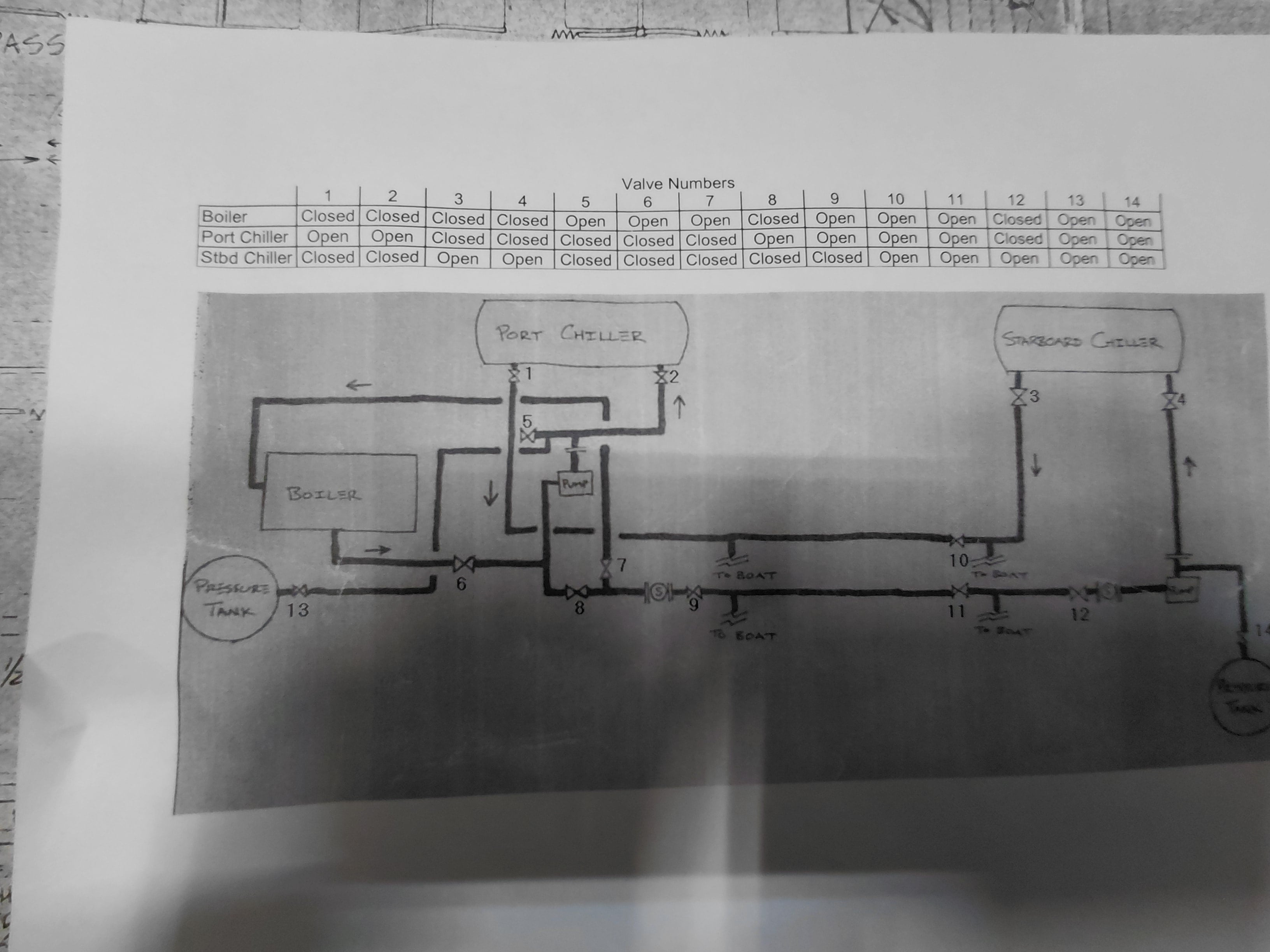
So taking a trip down memory lane. The Ship origionally had two chillers and two circ pumps. When the moved the boat to the pacific north west they decided they didn't need the second chiller so the removed it and its pump. Then they just opened the connecting valves, and upsized the single pump. As a part of that the re routed the boiler from the suction side of the pump to the discharge side, and slapped in a couple plain steel tanks.
 0
0 -
The air sep should be on the hot supply from boiler. Move expansion connection to suction of pump.
With a plain steel tank you have an "air managment" system. Air vented from the purger needs to go into the steel tank.
IF you had a diaphram or bag type expansion vessel, air can be expelled. Assuming there is a fill system to replace expelled air.
With glycol you want a fill tank, not a water connection for filling.
30- 35% glycol should be adequate. Look at the glycol tables for "burst" protection %
If the boiler gets valved off, add a sep on the chiller. On chilled water piping, the air sep goes on the return side, the warmer temperature zone.
With steel in the system, a magnetic dirt sep may be wise also. Or use combination separators.
Are there thermostats and zone valves? How is heat regulated at the coils?

 Bob "hot rod" Rohr
trainer for Caleffi NA
Living the hydronic dream0 -
When I encounter a system with an air problem, I often leave the automatic feed water turned on. That way, as the air is eliminated from the system, the feed valve automatically replaces the lost volume and maintains adequate system pressure.
Since maintaining a conventional water connection is not an option in your system, (unless you have a really long garden hose) you could accomplish essentially the same thing by using a Pressure Reducing Valve connected to a pressurized Well X Trol WX-203 tank. The tank could be filled with approximately 25 gallons of the proper glycol mixture and the air side pressurized to about 60 PSI.
The pressure-reducing valve would then maintain the desired system pressure by feeding glycol from the storage tank as needed when air is eliminated or a small amount of fluid is lost. This would provide a reserve supply of properly mixed glycol without introducing plain water into the system.
Here is a diagram you can post in the boiler room:

Heat operation noted above

Cooling operation noted above:
This will help keep air out of the system by design. With less air occupying space in the HVAC piping, the system will contain more heat-transfer fluid and, more importantly, maintain better contact between that fluid and the heat-transfer surfaces throughout the coils, chiller, boiler, and piping.
I don’t know what percentage of improvement you would actually see. That would depend on how much air is being eliminated compared with the amount of air the system normally operates with. A system with only a small amount of entrained air may show very little measurable improvement, while a system with significant air pockets or air binding could improve considerably.
There is also the issue of additional wear and deterioration. Entrained air can contribute to noise, poor circulation, corrosion, and damage to pumps, valves, heat exchangers, and other system components.
Edward Young Retired
After you make that expensive repair and you still have the same problem, What will you check next?
0 -
how are the floats in this stuff going to behave on a ship?
0 -
Does each each fan coil has a thermostat controlled off/on valve on coil? Or is control on fan? If former there should be a shunt somewhere to allow some flow when all coils are off.
Has someone tried to compare cost of operating with glycol versus running some heat during cold weather? Water source heat pump?
I believe that OP is correct about over sized circulating pump. It almost always is the case. Often coils near circulator require a balance valve or constant volume valve to work as expected. Again OP is probably correct. 4° delta on chilled water is not nice. Too fast flow is noisy and tough on chiller.
0 -
all the Caleffi Discals have a pin that the float rides on, so out of plumb is not an issue.
Set one on its side and shake it, float moves freely. I’d add a hydroscopic cap also.
But we suggest vertical installation. Although ships at sea may not always allow a vertical/ plumb position😏
 Bob "hot rod" Rohr
trainer for Caleffi NA
Living the hydronic dream 1
1 -
some amount of outdoor reset would help keep the coils with the fan off because the zone is satisfied from overheating or overcooling by convection as much.
0 -
A PAB pressure activated bypass would be an option if the coils have on/off zone valves
But an ECM circ in delta P mode adjusts gpm based on the number of valves open or closed
A Grundfos like this can cover 75 gpm, a 600W pump!


When all valves are closed it idles to a very low rpm, low power consumption mode.With a VFD if only one or a few zones are open you will still be overpumped and possibly have velocity noise and erosion
I would invest in the right sized pump, instead of running a grossly over sized pump way off curve
Easy to determine gpm, head may be a challenge. The chiller may be higher pressure drop than the boiler
Ideally the chiller and boiler would have correctly sized pumps. And primary secondary would be a great option with two different heat cool sources
Bob "hot rod" Rohr
trainer for Caleffi NA
Living the hydronic dream0 -
Some considerations about adding a VFD
Ideally you have a motor rated for inverter service.
You may not go below 50% or the motor will over heat
You would like your know the system curve, have it to lay over the pump curve
If you have a flat curve pump, depending on the system curve, you may run out of flow at the reduced speed
Do do some homework, get the pump data at the least, before you invest in a drive
A clamp on flow meter could give you good info,
Pressure reading across the pump is useful
Also the piping size will be what determines how many gpm you can flow before exceeding the 4-5 fps velocity where noise and wear become an issue
2”pipe is good for around 40 gpm, if 65-75 gpm is what you need??
The enginneringtoolbox online has all sorts of pipe flow data, gpm, velocity, pressure drop , etc.
Bob "hot rod" Rohr
trainer for Caleffi NA
Living the hydronic dream0 -
Is the boiler a condensing boiler or does it share ships power? If so have you checked the flue for condensate drainage and or pitch? On a boat this can be extremely troubling. They usually go straight up.
LANGAN'S PLUMBING & HEATING LLC
Considerate People, Considerate Service, Consider It Done!
732-751-1560
email: langansph@yahoo.com
www.langansplumbing.com0





Categories
- All Categories
- 87.8K THE MAIN WALL
- 3.3K A-C, Heat Pumps & Refrigeration
- 59 Biomass
- 430 Carbon Monoxide Awareness
- 133 Chimneys & Flues
- 2.2K Domestic Hot Water
- 6K Gas Heating
- 124 Geothermal
- 170 Indoor-Air Quality
- 3.8K Oil Heating
- 79 Pipe Deterioration
- 1.1K Plumbing
- 6.7K Radiant Heating
- 396 Solar
- 16.1K Strictly Steam
- 3.5K Thermostats and Controls
- 56 Water Quality
- 51 Industry Classes
- 51 Job Opportunities
- 18 Recall Announcements