Circulator/Mixing Valve Location on Heating System Piping

Hi. I have a question about where the circulator should be located on a heating system like mine.
I have an oil-fired, hot water boiler heating system. The boiler, near boiler piping, and components on those pipes near the boiler, were recently replaced. They service the legacy gravity heating system in my 1917 era house. The legacy piping and cast-iron radiators remain in place.
The system fails to heat the return water to the temperature required to mitigate condensation. A discussion about that is here: https://forum.heatinghelp.com/discussion/204273/water-temp-when-hydronic-system-is-not-running
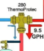
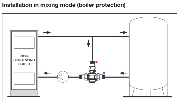
Recommendations offered by forum members show the circulator both 1) upstream and 2) downstream of the mixing valve, but in an official Caleffi video on YouTube, two Caleffi guys state emphatically that the circulator must be downstream of the valve.
How Can I Protect a Boiler System from Condensation? - Ask Caleffi #23 | Caleffi North America
Caleffi Hydronic Solutions
In the video the Caleffi Tech guys say:
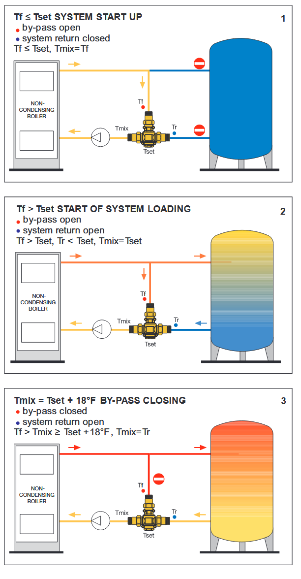
“Pump location is big with these, honestly, it’s gotta be on the return pulling water, pushing water back into the boiler, pulling water through the valve…You gotta have the pump pulling through the mixing valve so it’s gonna pull down through the bypass, pumping through the boiler, as that bypass starts to close it’s going to be pumping now out to the system.”
Below is what they say about a system that was piped another way because that was the only way there was room for it. The Caleffi guy says a tech tried this and found it doesn’t work. He further explains:
“There’s a reason why it’s not working. It’s not gonna, if you don’t pipe it the way we show you in the diagram…It’s not gonna sense and register temperature and react as it should if you’re not pulling water through that valve. This is where the 281 kinda makes it a little easier for an installer - the pump is there where it needs to be and it’s gonna work properly when installed properly but you don’t have to worry about sizing the pump.”
Just to keep things straight in my own head, I’m adding three side notes here:
1-In the video the techs refer to the circulator as a “pump”.
2-If the pump aka circulator is upstream it pushes water through the valve
3-If the pump aka circulator is downstream it pulls the water through the valve.
Questions:
1-Will both locations, upstream/downstream work?
2-Is one better than the other?
(I'm new to this forum. I see below a 2nd image of the video. I can't figure out how to delete it. Sorry.)
Comments
-
I have a system where this valve (the Caleffi 280) was installed after the pump (so its boiler outlet → pump → tee off to Caleffi 280), which is the opposite of what you see recommended in that video. This is also the opposite of how its piped in the instruction manual for the valve.
I am going to have this rectified later this summer/early this fall for a variety of reasons, but one of them is that it is indeed not what the manufacturer suggests! Caleffi technical support gave me this advice on why the valve should be on the system return side:
"we always want to pull the water through the mixing valve. This way it can pull equally from the hot and the cold side of the valve. If it would be on the supply side right before there is a chance of the supply/hot water over coming the return and pushing through."
Good luck finding an installer who will read the manual ;)
0 -
@HomeOwner7 I am not familiar with the Caleffi valve, but pumps should be pumping away from the expansion tank if possible.
I could look it up and figure it out but I am lazy right now.
but the Caleffi expert ( @hot_rod ) will comment on your system
In the meantime post some pictures of you system so we can see what is what. @hot_rod will fix you up.
0 -
It seems to me there is two conflicting strategies about moving water is these systems (only one circulator and one mixing valve). Since you seem to want to go in the direction of using the mixing valve to solve the return water temperature issue, you probably should follow the mixing valve manufacturer's instructions for best mixing valve performance.
National - U.S. Gas Boiler 45+ Years Old
Steam 300 SQ. FT. - EDR 347
One Pipe System0 -
I modified @EdTheHeaterMan drawing a bit, putting the circulator pumping out of the 280 valve, into the boiler return.
Locate expansion tank just upstream of the new circ location, so now you are pumping away from the PONPC. Fill valve connects at that point also.
Air purger stays at the boiler supply, where your system has it now.
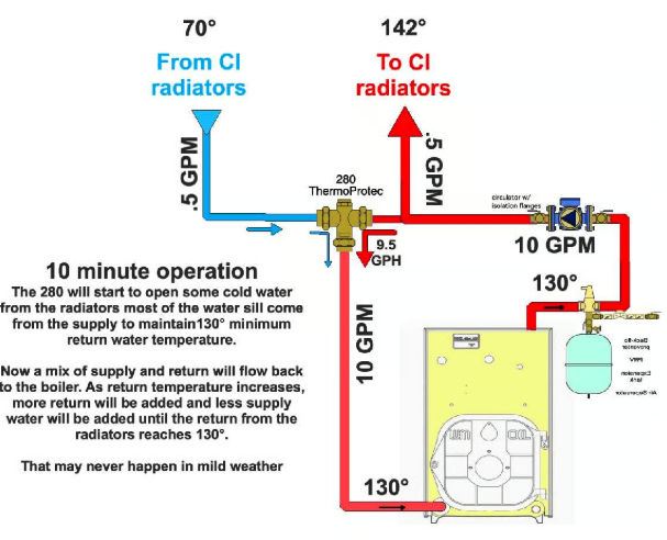
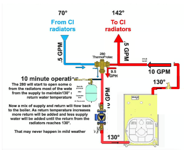 Bob "hot rod" Rohr
trainer for Caleffi NA
Living the hydronic dream0 -
That set of diagrams just above is sightly — and quite unintentionally — misleading. What is critical — and somewhat misleading again — is that however you pipe the thing, the suction of the boiler circulating pump (a circulator, @HomeOwner7 and a pump are the same — just different applications) must be on the mixed output from the valve. Which it has to be, to make the system work. Whether the pump is before or after the boiler in the boiler loop isn't relevant. Either location will work.
Br. Jamie, osb
Building superintendent/caretaker, 7200 sq. ft. historic house museum with dependencies in New England0 -
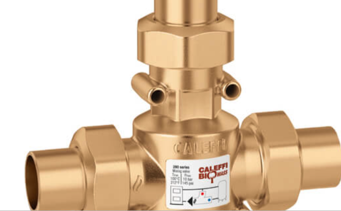
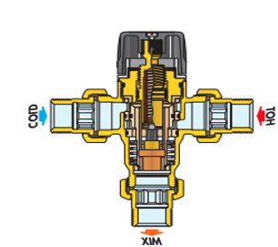
Most important is you connect it properly. The label on the valve has color dots to simplify the piping. Red for boiler supply, BLUE for system return. With any mix valve you like to pump away from the mix port.
Those round openings are gauge wells so you could monitor all there ports. When it is flowing.
With a low (no) pressure drop boiler, the pump could be up on the supply, but at some point, hydraulically speaking you would be pumping into the valve. The pump close to the mix port just clears up any confusion.
Isolation valves on 3 connections, the pump iso valves serve as on isolation.
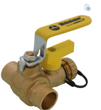
Use a Webstone purge ball valve at the return port and you have a nice purge point, isolation, and drain port to service the 280. Pay attention to the handle orientation :)
\
 Bob "hot rod" Rohr
trainer for Caleffi NA
Living the hydronic dream0 -
For me the main take off of the Pod Cast is both loops, boiler through bypass and boiler through radiation, both loops have to flow through the return pipe to the boiler. Since the Tmix port is apparently where the thermostatic control is, the Tmix port of the mixing valve has to be connected to the return pipe to the boiler to properly control the return water temperature.

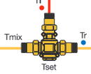
I believe the drawing posted here from the other thread does not properly illustrate that concept for boiler protection. In other words the way the pipes are shown they are not connected to the correct ports of the mixing valve.
Also I agree with @Jamie Hall about the location of the circulator. To me the boiler and the water does not expand or contract much with the influence of the circulator. So I would expect the water flow through the Tmix port of the mixing valve to be adequate. The Pod Cast method minimizes any confusion.
National - U.S. Gas Boiler 45+ Years Old
Steam 300 SQ. FT. - EDR 347
One Pipe System0 -
When in doubt, foillow the manufacturers drawing, shown here, for the Caleffi 280. Other brands of valve may differ.
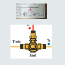
I think @EdTheHeaterMan was just illustrating the concept, with a typical 3 way thermostatic valve in mind. With a common 3 way, his drawing is accurate. Flip the valve to suit the orientation needed.
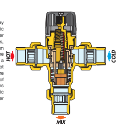
it's the pump to expansion tank relationship that needs to be correct. The tank needs to be on the suction side. So it adds it's delta P. Pumping Away. It's not about expansion.
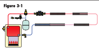
In this drawing fig. 3-1 you are pumping away from the tank PONPC. Start moving the circ around the loop, clockwise. At some point you are pumping at the PONPC. It is a hydraulic calculation used to determine the point where you go from pumping away to pumping at the PONPC.
But it is easy enough to avoid the confusion, keep the PONPC, tank close to the pump inlet.
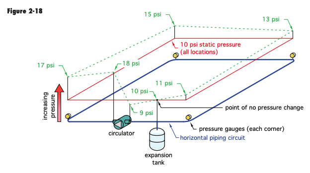
Fig. 2-18 shows the 8 psid being added to the 10 psi static pressure when you pump way.
The farther away from the suction the tank connects, the more of a psi droop on the inlet. This shows a small 1 psi drop when the circ runs. Due to the small pressure drop in that distance of pipe between the inlet and tank connection. Which is depedant on the pipe size and flow rate through it.
With the tank connected like this the pump cannot,will not change that 10 psi static fill pressure at that exact poing
 Bob "hot rod" Rohr
trainer for Caleffi NA
Living the hydronic dream0 -
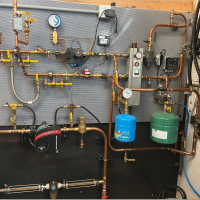
One of my coworkers was working on a large HW job at the University of MA. they were fixing some leaks and had to drain the system.
HP steam to HW converter with pump and expansion tank obviously. We had never worked on this system before and it was probably installed in the 50s
He was filling and bleeding and checking pressures and thought it was out of Wack. The pump suction was going into a vacuum. He noticed when bleeding with the pump on that it was sucking in air on some vents.
He called me and I asked, "are they pumping away from the expansion tank" he got going on "Its' not a boiler so it doesn't matter" and "the system has been here for 60 years" etc etc..
Typical guy who knows something is wrong and calls for help and he describes the problem you tell him what's wrong and he doesn't believe it because he doesn't want to. The pipe was too large to make moving the pump viable so i told him to move the expansion tank connection and I hung up on him because he wouldn't listen.
He finally did what I told him and it was fixed
Sometimes the mountain is hard to climb.
 1
1 -
Thanks, everyone, for offering your input. The information shared has better prepared me, a homeowner, to go on to the next step. My plan is to get the issue with my heating installation resolved before the next heating season.
0




Categories
- All Categories
- 87.8K THE MAIN WALL
- 3.3K A-C, Heat Pumps & Refrigeration
- 60 Biomass
- 430 Carbon Monoxide Awareness
- 133 Chimneys & Flues
- 2.2K Domestic Hot Water
- 6K Gas Heating
- 124 Geothermal
- 170 Indoor-Air Quality
- 3.9K Oil Heating
- 79 Pipe Deterioration
- 1.1K Plumbing
- 6.7K Radiant Heating
- 397 Solar
- 16.1K Strictly Steam
- 3.5K Thermostats and Controls
- 56 Water Quality
- 51 Industry Classes
- 51 Job Opportunities
- 18 Recall Announcements