Power vent, burner, upstairs thermostat no power?

My new yorker boiler /furnace seems to have a short or a failed component or transformer? I know this because when it runs out of oil the power vent will continue to run. I shut the switch at the top of the stairs off to save on electricity. When I put more oil in I turn the switch back on, which turns the power vent on again, and then the beckett burner comes on. The primary control's light begins blinking and I start priming the pump process. Normal sequence of operation.
NOW the other day i got more oil, turned the switch at the top of the basement stairs on and no power vent. Everything seemed dead. Something has happened where it doesnt want to power on the power vent fan. The thermostat upstairs is also blank. The zone 1 box on the side of the boiler doesnt light up anymore. And the usual primary control blinking light is now blank. But I do see the light in the circuit board on the power vent which tells me that power is being supplied.
A little more info.. my low water cut off probe slowly drips water onto the bottom of the box. I did some work on it a couple christmases ago and used j.b weld to seal it the best i could to buy me some time. Probably last fall i noticed this repeated / rapid clicking i could here through the floor. It would actually cut the burner off and when it would stop the burner would come back on. I thought it was a loose connection somewhere in the low water cut off box.
I'd like to know how you guys would approach this? Very, very much appreciate all the help.
Comments
-
Well, step 1 is going to be to figure out how the unit is wired. There are several safety switches involved; some will be on the 120 volt power and some on the 24 volt. You need to trace the wiring and draw a diagram of it.
Then, step by step, from the emergency cutoff switch to the burner control, find out what is getting power and where it stops. Then find out why it stops there.
It may be the LWCO — it rather sounds as though that needs to either be replaced or completely overhauled. JB Weld is not a suitable repair product or sealant on a low water cutoff.
Br. Jamie, osb
Building superintendent/caretaker, 7200 sq. ft. historic house museum with dependencies in New England1 -
Stop running out of oil. Call someone who knows how to use an electric meter to troubleshoot components.
Could be as simple as a bad thermostat, or it needs batteries.
The LWCO should be replaced. But first, take it out of the circuit to see if everything works as it should. 2
2 -
rapid clicking could be a lot of things but i your case i would be suspicious of a loos low energy wiring connection, but it could be a bad or loose relay too or bad contacts somewhere else
1 -
The power venter may have something to do with the rapid clicking mentioned above. The clicking could be a relay, control board, or draft-proving switch repeatedly attempting to start or prove the power venter.
If there is no power reaching the power-venter control, a switch or control in the circuit supplying it may be open. That would be an open circuit, not a short circuit. However, the exact location of the open circuit depends on how this particular system is wired.
From what I have read so far, the LWCO may be wired in series with the other burner limit and safety controls. A simplified control sequence might look something like this:
120 V L1 hot → service or emergency switch → burner switch → LWCO and other limit controls → power-venter control → burner primary control → burner motor and ignition → return path to Neutral
The actual sequence may be different. On many power-vented systems, the power venter starts first. A pressure or airflow-proving switch must then confirm adequate draft before the burner primary control is permitted to start the burner.
If that is approximately how your controls are wired, the problem could be somewhere between the incoming 120-volt power supply and the power-venter control, or it could be within the power-venter control or its proving circuit.
You mentioned that a power LED on one of the circuit boards is illuminated. That confirms that power is reaching that particular board, but it does not, by itself, prove that the LWCO is open. An LWCO is commonly wired in series with the other limit controls and can prevent the burner from operating when it senses a low-water condition, but voltage readings on both sides of the LWCO and the other safety controls would be needed to determine where the circuit is opening.
If you could provide the part numbers or photos of all the components, I could draw you a probable wiring diagram that will explain your situation.
OR
You could just add water to see it the LWCO is showing a low water condition.
Edward Young Retired
After you make that expensive repair and you still have the same problem, What will you check next?
0 -
Forget about sending pictures. I was able to read all the info about your boiler from the previous post from 2024 when we gave you the 3 week crash course on oil burner combustion, hydronics and electrical controls. I think your loosing power at the LWCO. Do you have an electrical meter? Open the LWCO box asd see what terminals you have power to when you touch one of the meter leads to the case (Ground) and the other to each terminal.
Edward Young Retired
After you make that expensive repair and you still have the same problem, What will you check next?
0 -
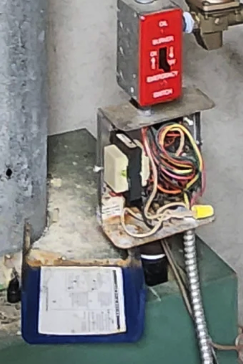
Sounds like the power vent is powered but not getting a call since every thing else is dead. I saw you have a meter in one of the photos. Divide and conquer, pick an easy spot like the switch just above the LWCO with the Red cover plate or the LWCO to see where the power stops. Got power go further into the system, no power go towards the power coming into the power vent.
Maybe the corrosion in the LWCO finally had its way with it.
 National - U.S. Gas Boiler 45+ Years Old
Steam 300 SQ. FT. - EDR 347
One Pipe System 2
2 -
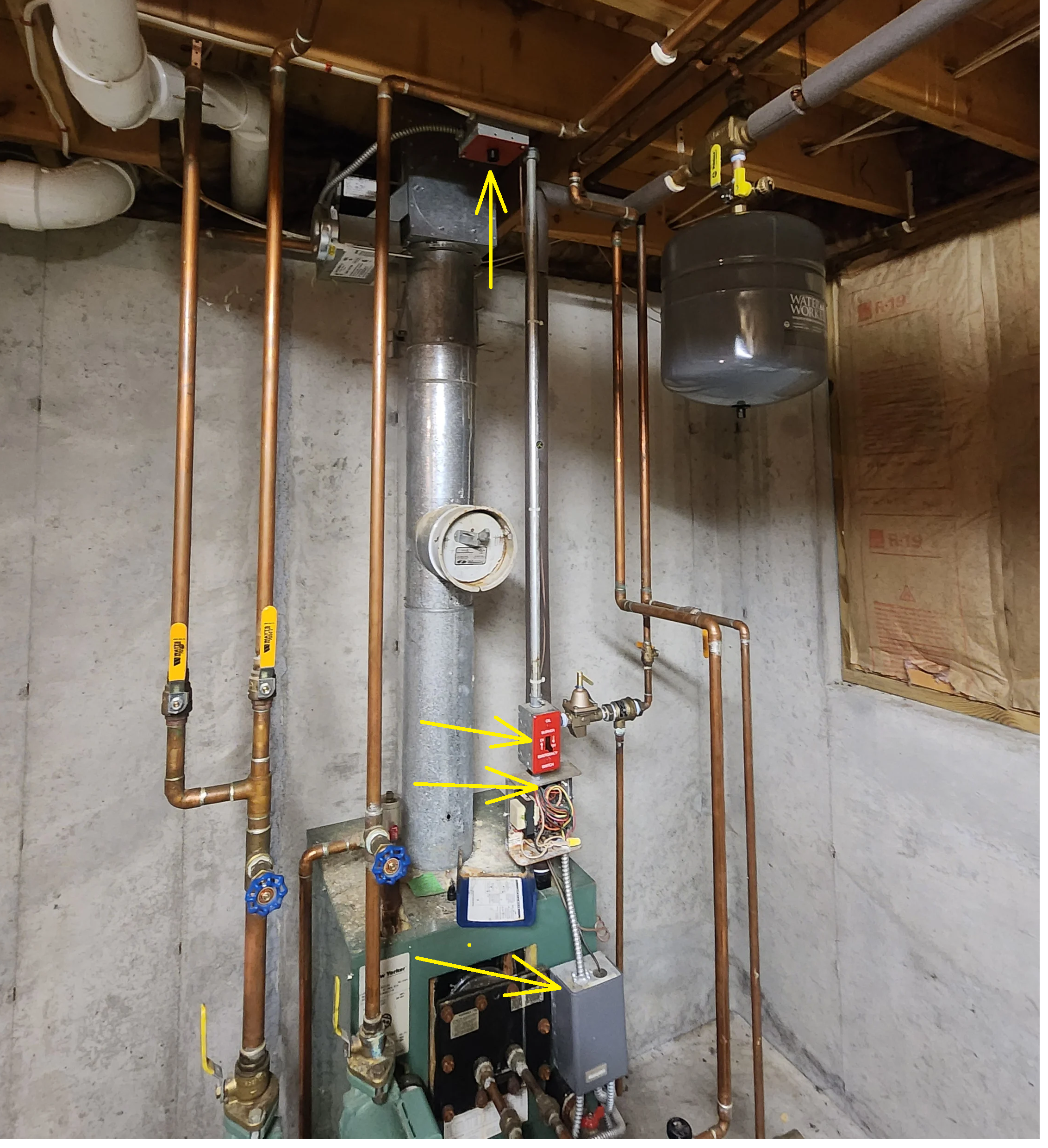
Based on these two photographs of your system, this is the wiring diagram I developed. It will work; however, there may be more than one way to wire this configuration of controls.
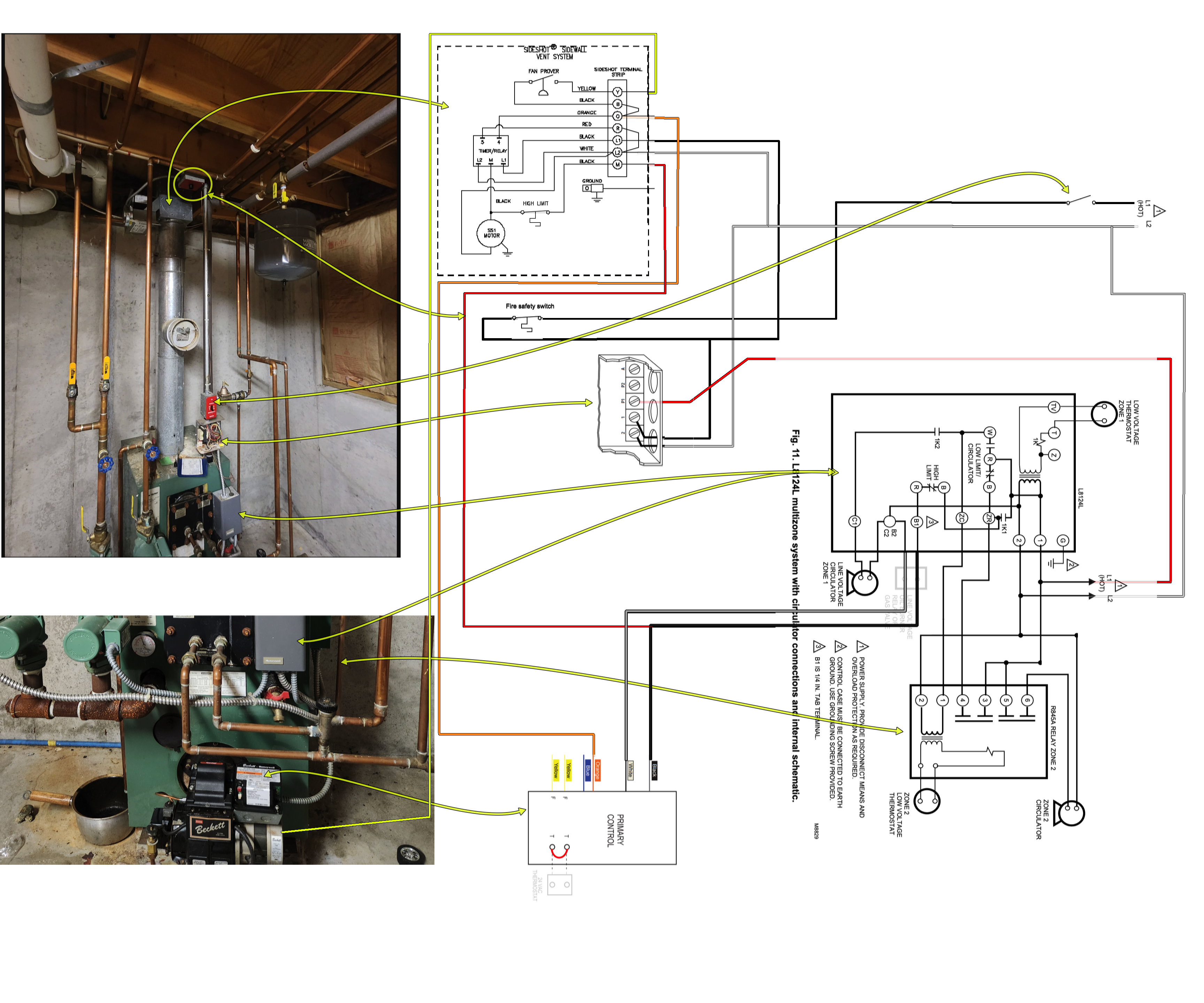
In this configuration, the sequence of operation (SOO) is as follows:
- With the burner emergency switch and the fire-safety switch connected in series and both switches in the ON position, 120-volt power is supplied through them and all the Neutral or L2 terminals from all the devices and loads are connected to the 120 V neutral.
- From the fire-safety switch, the power-vent control is energized at L1, and the LWCO is powered at L1.
- Power then passes through terminals P1 and P2 on the LWCO and supplies 120 VAC to L1 on the L8124 aquastat.
- On a call for heat from any zone thermostat, terminal B1 on the L8124 becomes energized and sends 120 VAC to the L7148 primary control and to terminal M on the power-vent control, starting the power-vent motor.
- The primary control then supplies power through the Orange and Blue (and in some cases a Violet) wires to energize the burner ignition and the Orange-wire circuit in the power-vent control. The power-vent pressure switch proves that sufficient draft has been established. The Yellow wire then supplies 120 VAC to the burner motor and/or oil valve.
- The burner ignites the oil, and a flame is established.
- When the call for heat is satisfied, the burner motor and/or oil valve stops, and the flame is extinguished.
- The time-delay circuit in the power-vent control keeps the power-vent motor operating for the preset post-purge period.
This is the normal sequence of operation.
If an out-of-oil condition occurs, the burner will shut down on safety, and the burner motor will stop. However, terminal B1 on the L8124 will remain energized as long as the call for heat continues. This sends 120 VAC to terminal M on the power-vent control and should keep the power-vent motor operating.
In this situation, the burner apparently ran out of oil, but the power-vent motor did not continue to operate. This indicates that another switch or circuit is open ahead of the L8124 aquastat control.
Because the LWCO indicator LED is illuminated, power has reached the LWCO at terminals L1 and N, or L2. Therefore, the open circuit is most likely located at the LWCO output or somewhere between the LWCO P1 and P2 terminals and the L8124 aquastat. That would be my guess.
I believe that @109A_5 may concur or may have a different wiring configuration. but either way the LWCO will be the place to check first.
Edward Young Retired
After you make that expensive repair and you still have the same problem, What will you check next?
1 -
Here is a copy of the wiring diagram without all the extra yellow arrows showing which component on the boiler corresponds to each part of the diagram.
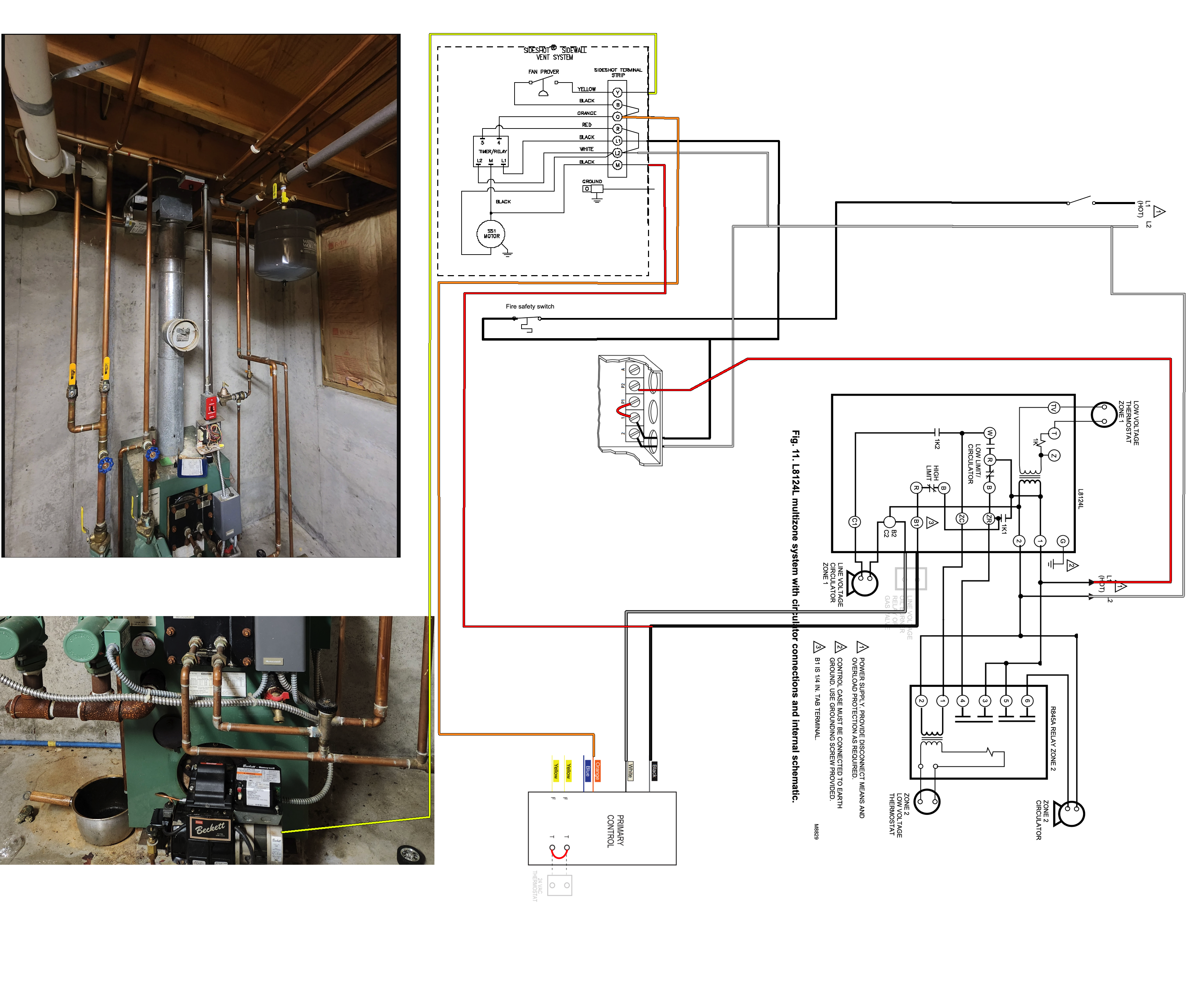
…and of course this diagram assumes that the second zone control for the circulator is wired correctly for DHW priority. I have seen more than my share of incorrect zone control wiring that leads to a chronic insufficient hot water situation .
Edward Young Retired
After you make that expensive repair and you still have the same problem, What will you check next?
0 -
Some things I wonder; Does the switch just above the LWCO actually cut power to the thermal safety switch and the power vent.
And
Does the " I shut the switch at the top of the stairs off to save on electricity. " shut the power off to everything ?
Depending on where the defect is, knowing how it's actually wired may help.
@EdTheHeaterMan wrote " Because the LWCO indicator LED is illuminated "
@ColdMainer wrote " But I do see the light in the circuit board on the power vent which tells me that power is being supplied. "
So it's the power vent that has power. LWCO's power is unknown.
I'd be curious about the way the switch and the thermal cut off is wired and what does the switch just above the LWCO actual cut power to.
National - U.S. Gas Boiler 45+ Years Old
Steam 300 SQ. FT. - EDR 347
One Pipe System0 -
@ColdMainer is the homeowner and I doubt that they will be able to tell us the actual order of the switches in series with the 120 VAC power supply. It would only be a guess but if I was the professional that originally connected the wires to that boiler system I would want any service switch (top of stairs, or emergency switch above the LWCO or any other manual switch) to be able to cut power to the controls that I would want to service. If that is the case then the fire safety switch on the ceiling would come after the manual switches. That said, the next switch in line might be the fire safety switch. But that is not a guarantee. The fact that the normal out of oil condition is that the power vent fan motor operates tells me that the problem with the power vent motor not operating now means that the B1 from the L7224 may not have 120 VAC to send to the M terminal on the power vent control. Also I'm not even sure that the power vent control is the one I have shown on the diagram. I just took an educated guess based on the age of the equipment and what looks like a SideShot power vent.
With that info and assumptions, I believe that a jumper wire between the P1 and the P2 terminals on the LWCO will be the fastest way to test to see if the LWCO is the source of the problem. and again I'm not even sure of the model number of the LWCO.
Edward Young Retired
After you make that expensive repair and you still have the same problem, What will you check next?
0 -
after further research and finding @ColdMainer's post bout hi Tjerndlund SS1, I see that there is a UC1 control so I have updated the wiring diagram here:
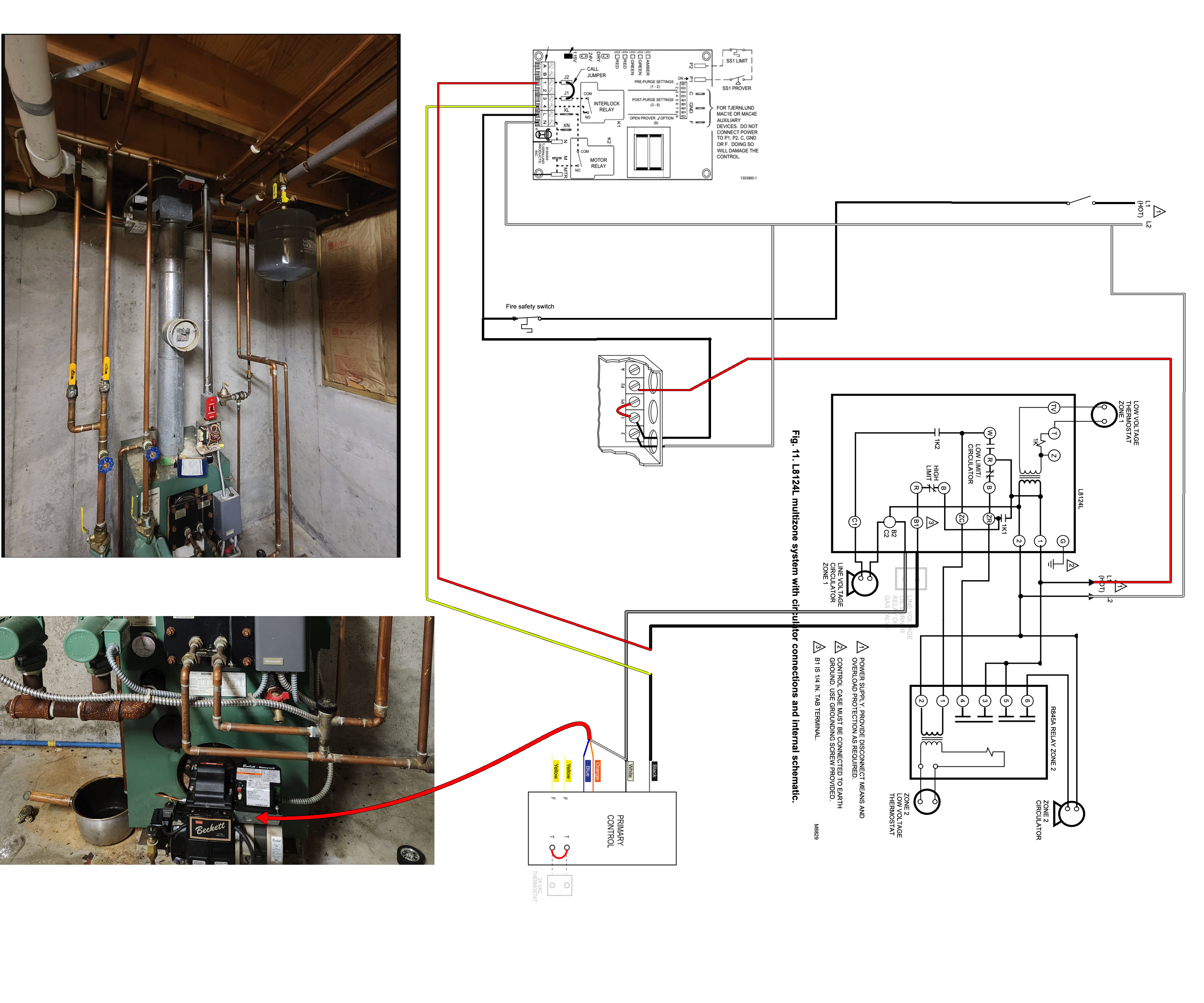
this update will still operate as described on the out of oil condition and still points the the LWCO as the probable cause, however the L8124 aquastat relay may be the problem also. that is why we need to look and the LWCO with a meter and perhaps place a jumper wire from P1 to P2 on the LWCO (still not sure about the LWCO model number). Then if that does not start the vent motor I would suspect that L1 on the L8124 aquastat relay is not getting power or there is an internal problem on the L8124 if L1 has power.
Edward Young Retired
After you make that expensive repair and you still have the same problem, What will you check next?
1 -
As a wiring clue, simply operate both switches, one at a time, and see if either or both shut off the " light in the circuit board on the power vent ".
You can also count the number of wires leaving the top of the switch box just above the LWCO. Is there 2, Hot and Neutral or maybe 4 where the Hot doubles back up after the switch to power the power vent and goes through the Fire Safety switch / Thermal Cut-off on its way back to the LWCO and the Boiler's burner etc.
National - U.S. Gas Boiler 45+ Years Old
Steam 300 SQ. FT. - EDR 347
One Pipe System2 -
I'm sorry it took me so long to reply. July has been really tough for me and the fam. I really appreciate all the help in here.
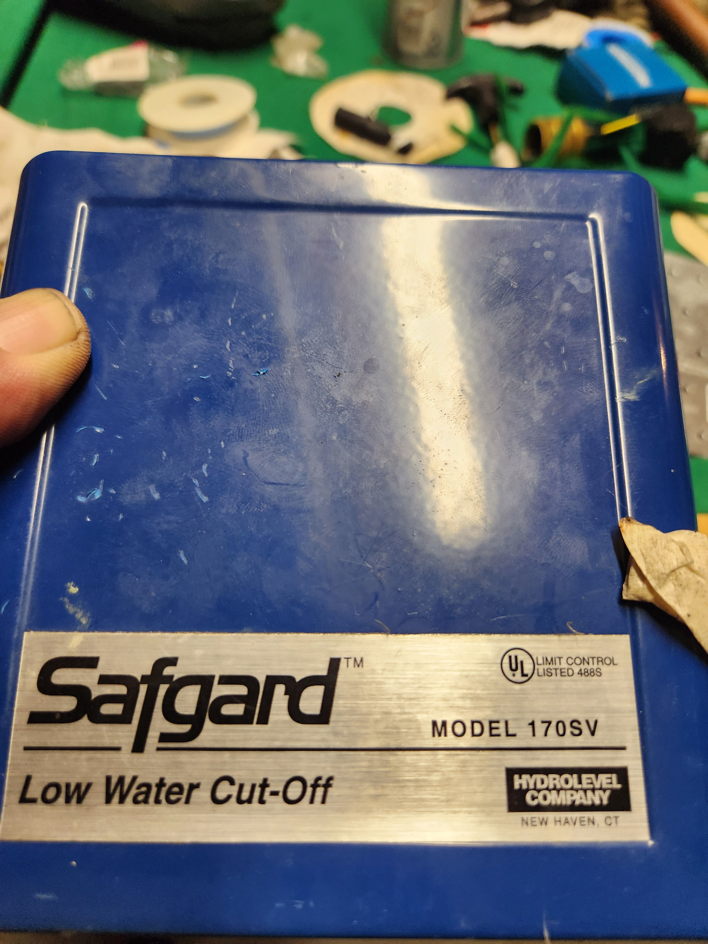
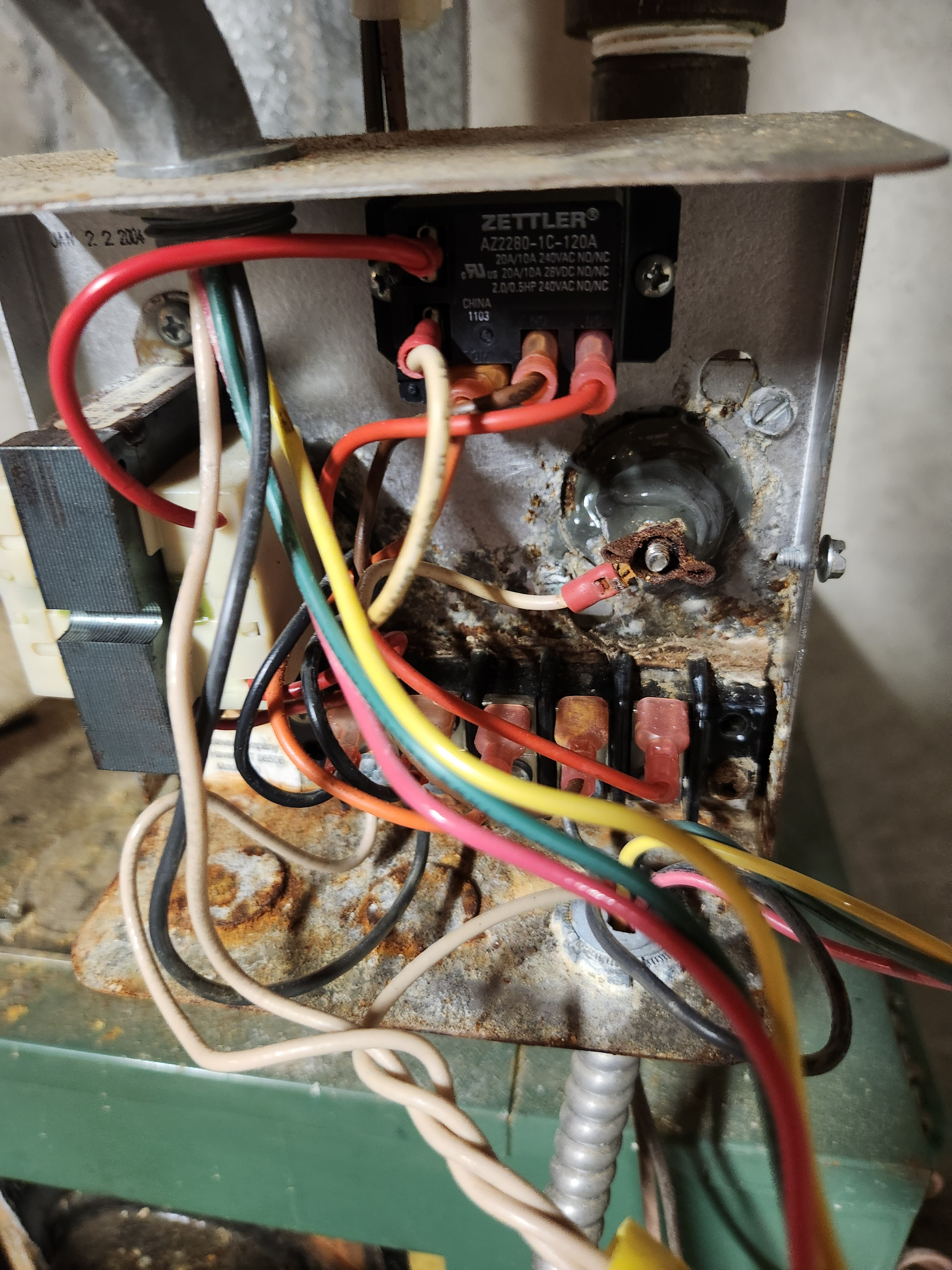
So my boiler started working again. I went down and flipped the burner switch on and it worked its way out of it on it's own. I heard a funny little micro sound come from a solenoid or something powering up right before the power vent came on and things started running. Just one look at the LWCO box and you know its gotta be the issue. Crusty!
I just worry. If I dont take care of it now it will come back to haunt me in January.
0


Categories
- All Categories
- 87.8K THE MAIN WALL
- 3.3K A-C, Heat Pumps & Refrigeration
- 60 Biomass
- 430 Carbon Monoxide Awareness
- 133 Chimneys & Flues
- 2.2K Domestic Hot Water
- 6K Gas Heating
- 124 Geothermal
- 170 Indoor-Air Quality
- 3.9K Oil Heating
- 79 Pipe Deterioration
- 1.1K Plumbing
- 6.7K Radiant Heating
- 397 Solar
- 16.1K Strictly Steam
- 3.5K Thermostats and Controls
- 56 Water Quality
- 51 Industry Classes
- 51 Job Opportunities
- 18 Recall Announcements