Theoretical radiant output

Where can I find a more complete formula for calculating radiant floor output which accurately accounts for tube spacing, heat spreader, water temperature, flow rate and floor covering R-value?
Comments
-
A single formula is not going to do it. That is not to say that the temperature of the radiating surface (the floor surface exposed to space, which is the governing variable in heat transfer to the space) can't be modelled — it can, and all the items you mention factor into the models. Several firms have the capability of doing this more or less accurately for you — at least two pop up on The Wall from time to time and may see this thread.
That said, a calculation which comes within 10 percent is going to be the best your can hope for in a real world situation.
Br. Jamie, osb
Building superintendent/caretaker, 7200 sq. ft. historic house museum with dependencies in New England1 -
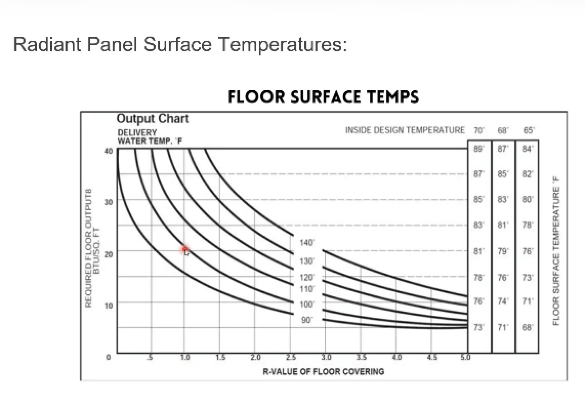
Any radiant panel output is based on the floor surface temperature and the ambient air temperature of the space.
In a residence you want to keep the floor surface below 82° or it becomes uncomfortably warm to bare feet.
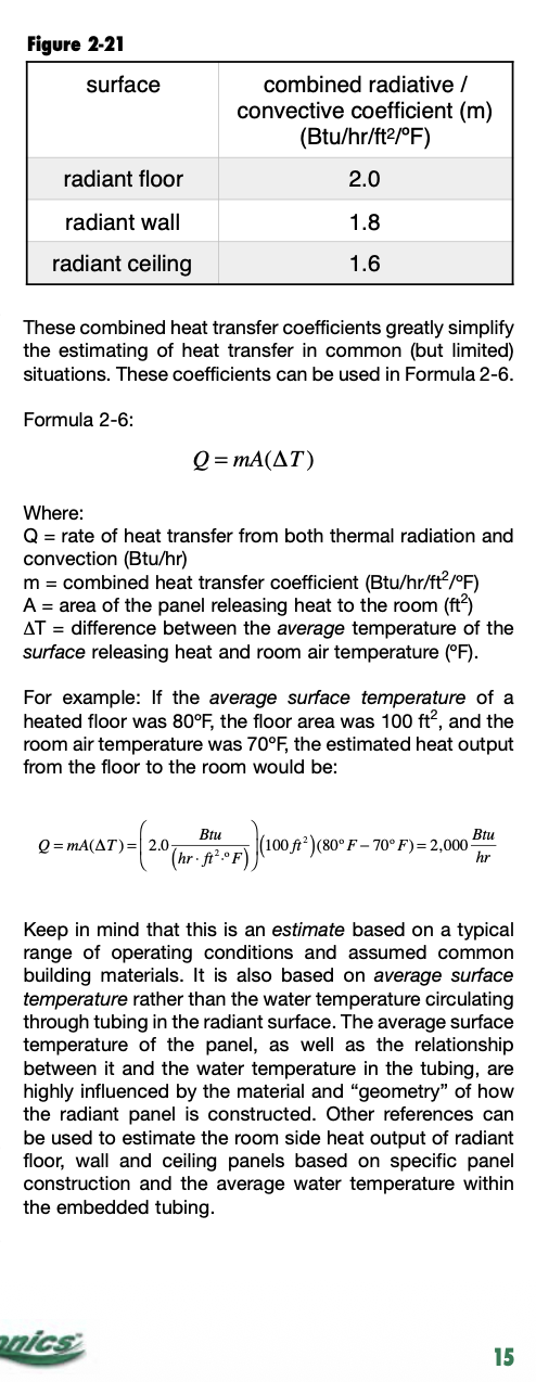
So here is some math for various radiant panels, floor, wall and ceiling. From Caleffi Idronics 25
So for a room at 70° ambient with average floor surface of 82, 82-70 X 2 = 24 btu/ sq ft output.
Often when you see higher floor output it is because the room temperature is lower. At 65 ambient
82-65= 17X 2= 34 btu/sq ft. That may be fine for a shop, but a little cold for me at 65°
 Bob "hot rod" Rohr
trainer for Caleffi NA
Living the hydronic dream0 -
Thank you, as always, @hot_rod . For @dcwittlo , that is exactly the kind of approximating approach to which I was referring. As the reference notes — and I noted — going from the variables which you mention to the heat output can also be estimated using various sources — but to get to anything much better than 105 you are going to have to go to finite element heat transfer modelling. And you don't want to do that…
Br. Jamie, osb
Building superintendent/caretaker, 7200 sq. ft. historic house museum with dependencies in New England0 -
Under a wood floor the subfloor and any final coverings subtract out.
From Uponor
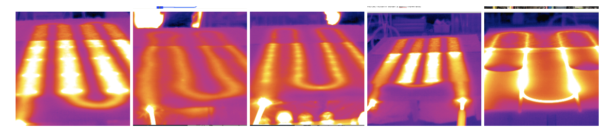
Thjerse infrared show the challenge getting the entire surface a consistent temperature. From left copper tube in 4" extruded aluminum plates
Suspended tube
Staple up EPDM
Pex in 4" extruded plates
Warmboard.
The back 1/2 of each sheet has berber carpet, no pad
The RadPad calculator is another way to run some output options.
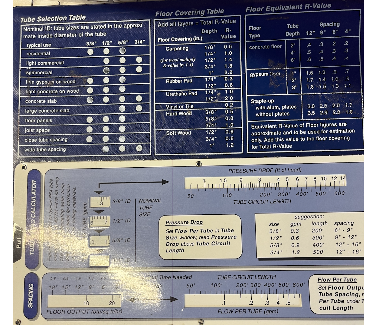
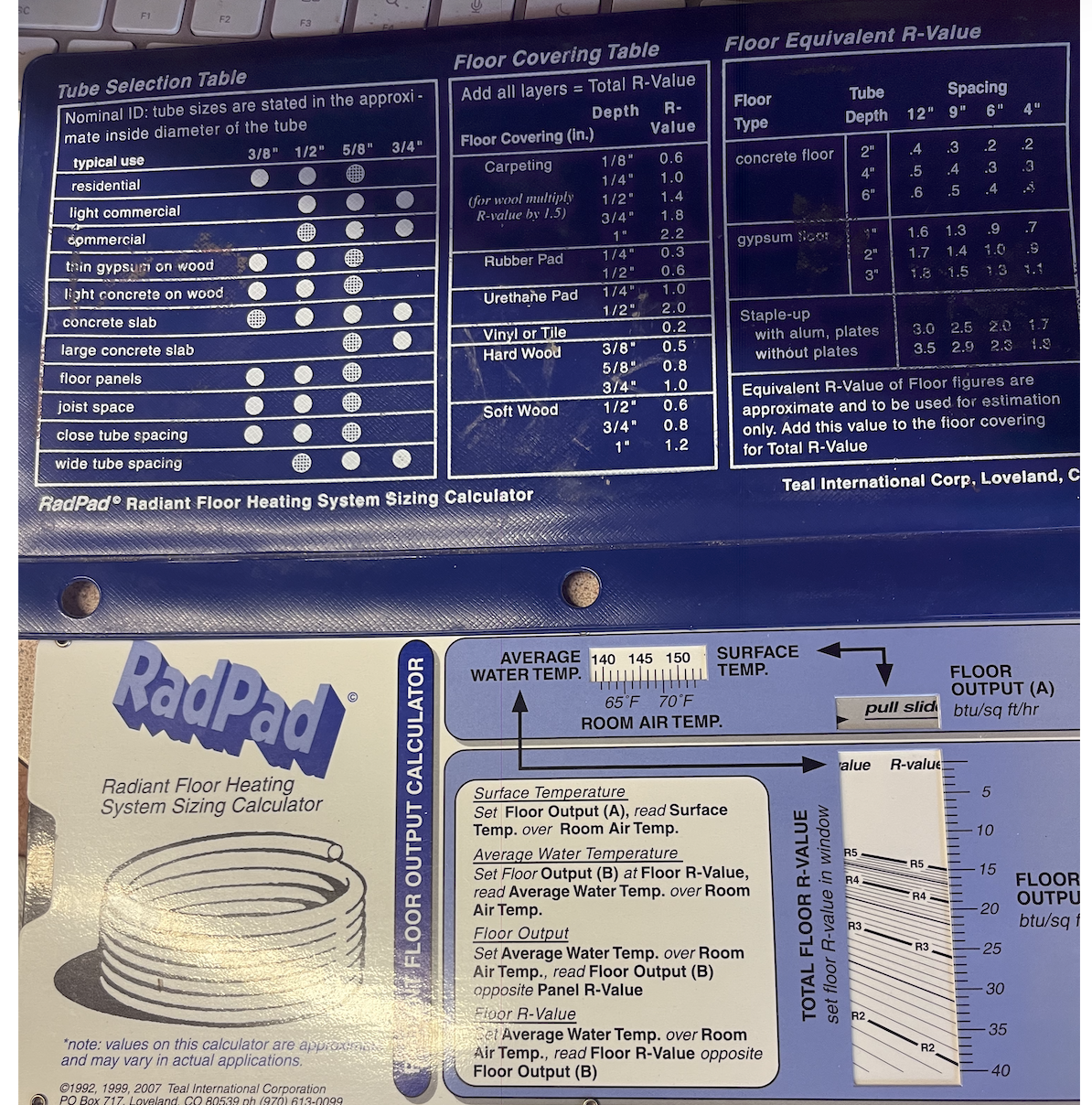
I do have some FEA models also, but the story is the same.
Bob "hot rod" Rohr
trainer for Caleffi NA
Living the hydronic dream
 2
2 -
what are the 2 cooler circles in the warmboard?
0 -
OK, now we are getting somewhere. Next part of the calculation is: How many BTU/hr/ft^2 if one is given the spacing of PEX tubing, flow rate thru tubing, supplied water temp of tubing and maybe the width or area of the aluminum heat spreader. Does it much matter how thick the aluminum is?
0 -
Sorry, my last post was a little late. I think you already answered these questions.
0 -
I routered across the sheet to make a return bend for another project.
It clearly shows the conductivity of the aluminum
Bob "hot rod" Rohr
trainer for Caleffi NA
Living the hydronic dream1 -
The grip on the Pex is more important than the thickness of aluminum plates. The extruded plates grip so well that you need to tap the tube in.
The thin flashing thickness plates can make some noise as they warp and the tube slides. A creaking noise from tube movement, an “oil can” noise as the plates expand and contract. Thin plates work if you lock them between layers of wood.Another key is to use a boiler or mixing device with outdoor reset so the plates don’t see wide temperature swings. Constant circulation is ideal.
Bob "hot rod" Rohr
trainer for Caleffi NA
Living the hydronic dream0 -
@hot_rod: Thanks for posting those photos, very interesting. Is the temperature scale the same for all of them? Because I'd expect the Warmboard to be noticeably warmer and evener than the plates, and it doesn't look that way. I'd also expect the copper pipe with plates to out-perform PEX, but that doesn't seem to be the case either.
Interesting, it looks like the carpet does more to reduce output on the Warmboard than on the plates.
0 -
What you see with the Warmboard may be the 12” spacing. All the others are 8” on center in a 14” joist bay, so the heat stripping is more pronounced.
Same SWT, same flow, same room ambient temperature.
Notice that the carpeted back half reduces the surface temperature, but it does also spread the heat across the surface a bit also.
The most consistent temperature spread I witnessed was the early SolaRoll mat systems. Both the width of the mat and the counterflow flow path with a hot supply next to a cooler return across the mat did the job well.
Dealing with 5/16” non barrier tube was another story,Bob "hot rod" Rohr
trainer for Caleffi NA
Living the hydronic dream0 -
Thanks a lot. This is exactly the kind of info I like to see. I would rather "do the math" than use "rules of thumb." I realize that even graphs and formulas are approximations since the formulas can't always account for real-world complexities. As an electronics engineer, I am accustomed to make allowances for real-world variations. I feel more comfortable using theoretical formulas and graphs based on known conditions and then applying my own allowances rather than using a rule-of-thumb that might not apply to my situation. I have some more questions but I think I'll post them under a different description.
Thanks again :-)
0 -
Electronics engineer? Be careful with your expectations. You don't have anywhere near the unknown unknowns that are present in heating and ventilating, and even the degree of unknown variation in the known variables is much much larger… in general, if you can get within 10% — one significant digit — agreement between the results from the graphs and formulae and what actually happens in real life you either have a VERY simple system — or are just plain lucky.
Br. Jamie, osb
Building superintendent/caretaker, 7200 sq. ft. historic house museum with dependencies in New England1 -
It's an iterative process.
First step is to do a room-by-room heat loss. It simplifies things to use the same water temperature for every room, so the next step is to figure out which room is going to need the hottest floor temperature. Go through the house room by room, and for each room figure out how many usable square feet of floor there is, floor that is covered by fixtures or cabinets isn't going to be usable for heating. Then divide the heating load for each room by the usable square footage to get BTU/hr per square foot. The highest one is going to determine your water temperature.
As a rule of thumb, you get 2 BTU/hr per square foot for every degree above room temperature the surface of the floor is. Floor heat works best with temperatures between about 77F and 87F, or 14-34 BTU/hr/square foot. Any higher than that and the floor starts getting uncomfortable, any lower than that and the floor isn't noticeably warm. There's no rule that says you have to heat the whole floor, so you can reduce the heated area to bring the temperature up. If you don't have enough floor area you have to think about other heat sources like radiators.
Then it's time to look at the other rooms. This is where the iterativeness comes in, if other rooms have wildly different heating loads per square foot you might need to revise your plan.
When you build the floors, it's important to have the ability to adjust the output in case your calculations end up being off. Usually the only lever available once the system is built is water temperature. Changing flow isn't going to change output that much.
0


Categories
- All Categories
- 87.8K THE MAIN WALL
- 3.3K A-C, Heat Pumps & Refrigeration
- 60 Biomass
- 430 Carbon Monoxide Awareness
- 133 Chimneys & Flues
- 2.2K Domestic Hot Water
- 6K Gas Heating
- 124 Geothermal
- 170 Indoor-Air Quality
- 3.9K Oil Heating
- 79 Pipe Deterioration
- 1.1K Plumbing
- 6.7K Radiant Heating
- 397 Solar
- 16.1K Strictly Steam
- 3.5K Thermostats and Controls
- 56 Water Quality
- 51 Industry Classes
- 51 Job Opportunities
- 18 Recall Announcements