Caleffi 280 Thermostatic Mixing Valve
Comments
-
I think its correct to say my radiators are "bigger" than my boiler: there's 2100 sq ft of EDR in old cast iron radiators, and using Formula 2-2 from iDronics issue 35, that tells me I'd get (need?) over 300,000 btu/hr with an average water temp of 170F and a 70F room. However, I should emphasize that during the cold snap the house was plenty comfortable with (if I'm remembering correctly) 130-140F water temps, which is ballpark 200,000 btu/hr using that formula. That plus my massive exposed supply and return lines in the basement probably matches the 235,000 btu/hr output of the boiler. The boiler didn't run the entire day, but plenty of it (I think 16-17 hours according to the ecobee logs).
Yes, during recent service calls the boiler does cycle off, and I verified (on the control board's LCD screen) that the boiler temp during these short off cycles is near the setpoint (178-179F).
I have ordered the 130F cartridge and will give that a shot, but your previous message about the flow rates I need to get sensible delta T in my system makes me think I will probably need a different circulator. Is that right? One step up from the NRF-33 would be the NRF-36, I think. Would that be a good choice? What else could I do here?
0 -
I suppose it depends a bit on how the radiators are piped. If you end up with a wide delta the radiators at the end of a loop may not output enough heat?
That was the one design criteria with gravity systems the length of the run outs that would allow enough gravity flow. This is one reason B&G developed the "booster pump" to allow conversions, or performance improvements on gravity piping systems.
I would try the lower cartridge first. My concern is the mixing valve has added just enough flow resistance to push you to the limit, maybe beyond of what that pump can do.
But if the system ran those low SWT/ RWT without the valve, you really need a protection valve. you do not want to run that boiler constantly at 130- 140 supply temperatures. Did you note the return at the boiler at those temoerature conditions?
Without being able to calculate the piping circuit, it will take a few trial and error steps. If the pump is not up to the task you could upsize or add another 33 in series to double the head.
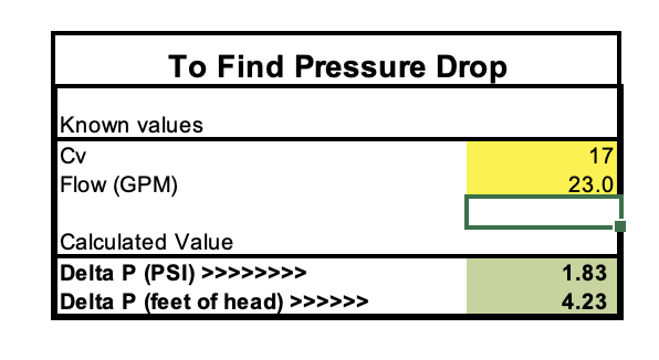
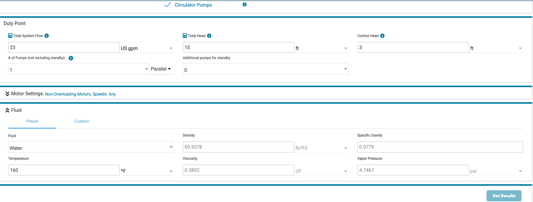
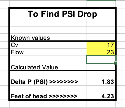
If we assume you in fact need to move 23 gpm to get the job done (230,000 @ 20∆)
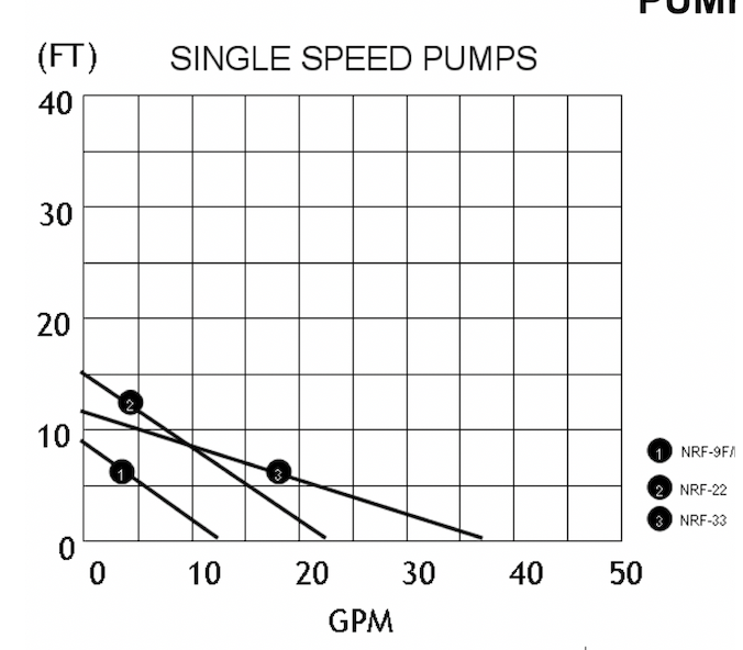
Looking at the pump curve the 33 will only get you about 5'. Two in series would get you closer to 10' head.
Attached is a 23 gpm flow in a 17 Cv valve, 4.23' head.
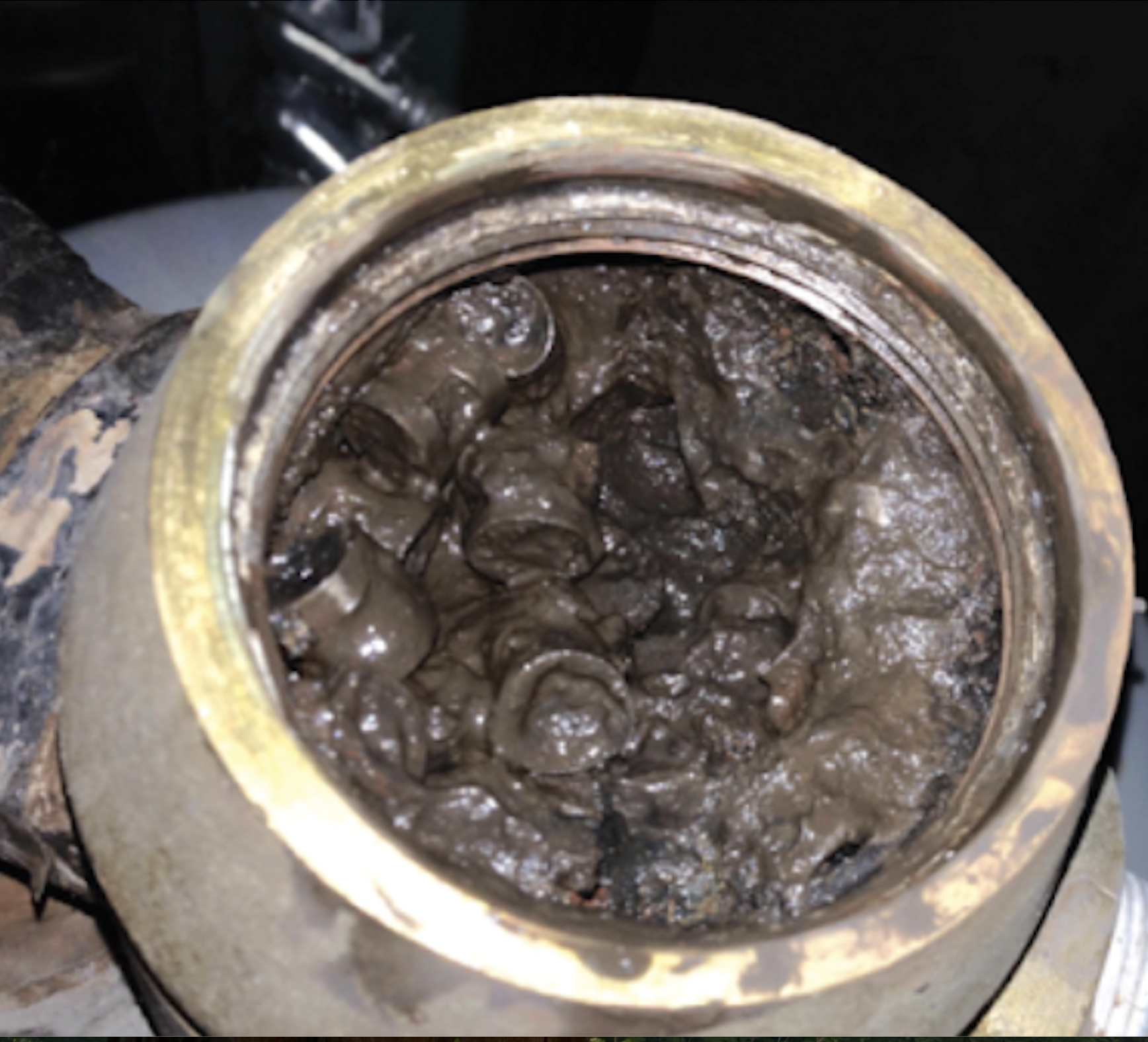
Another check would be to pull the top off the air sep, we have seen a number of cases where the mesh or media inside gets plugged with teflon tape , rust, sludge etc. That will add a bit more flow resistance.
But you want to get to a design condition or near it to get the info you need for the next step. It is always easier to get heating systems to perform adequately on mild days :)
 Bob "hot rod" Rohr
trainer for Caleffi NA
Living the hydronic dream0 -
I did use a (cheap/digital) strap-on temperature probe that I wrapped around the return pipe with some electrical tape and a piece of pool noodle for insulation prior to the install of the protection valve. That was giving me readings way below 120F nearly all the time, including at the end of heating cycles. I'm not confident that it was super well calibrated, but I would be surprised if it was 20F too low…. This is why I decided to install the valve in the first place.
regarding circulators: I think an NRF-36 fits exactly in the space that my nrf-33 currently occupies. If I find that I'm still getting (some) cold radiators after swapping out the 140F cartridge for the 130F cartridge, do you think this circulator upgrade would help?
0 -
More flow always = more btu output from the heat distribution. And yes even in cast iron radiators that were on a gravity system.
I've tested 4 different cast radiators from 1/2 gpm - 8 gpm. Increased flow always sped up the heat output and raised the average temperature across the radiator.
That being said once over 2-3 gpm the output increase is not very significant. See how the below curve flattens at @ 2 gpm. So depending on the pump size and power consumption the last few % may not be worth chasing. head loss increases with the cube of the flow rate. If flow is doubled head increases 3 to the 3rd power.
Graph 2-13 is pretty accurate for any type of heat emitter.
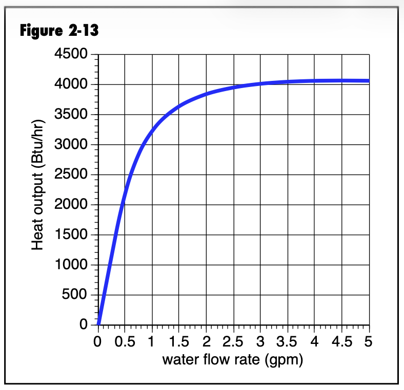
Fig 2-14 is a 250' loop of 1/2 pex in concrete, SWT costant 110°
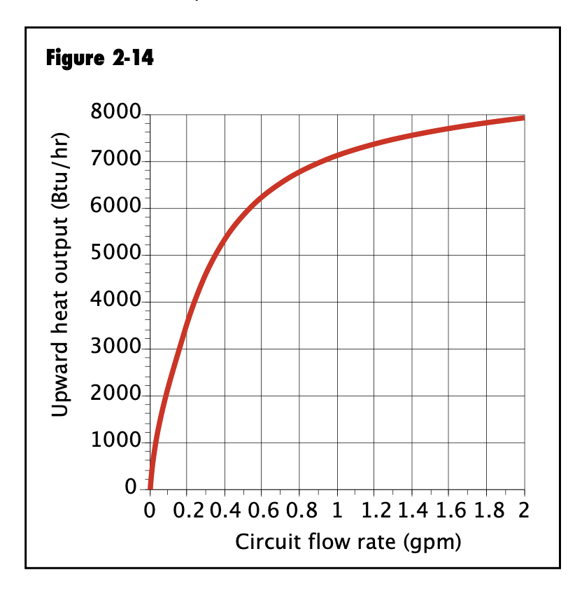
With radiators it is mostly a surface area game, the greater the surface area the steeper the slope.
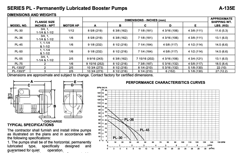
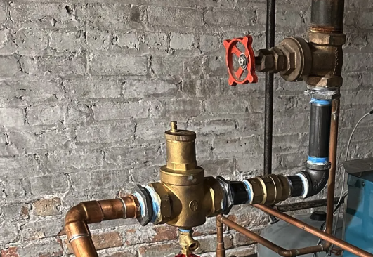
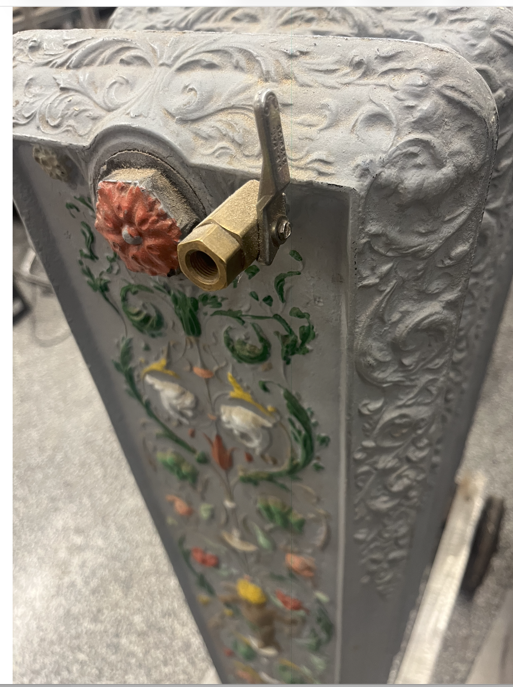
So to answer your question the PL 36, considered a high head circ, would move more gpm. I doubt with large diameter piping and wide open radiators that you will get velocity noise. This red valve looks to be a gate valve? If it is a globe valve it would be a perfect balance valve. Even the gate valve would allow you to do some balance.
The PL 45 is a bit flatter curve, but a bigger body pump 8-1/2" flange to flange.
If money were no object I'd consider a small Grundfos Magna that you could vary speed and save 50% or more on power $$ It would involve flange changes however.
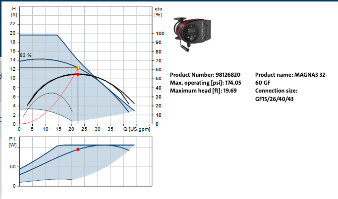
This small Magna in the 20- 25 gpm range is operating at 83% efficiency.
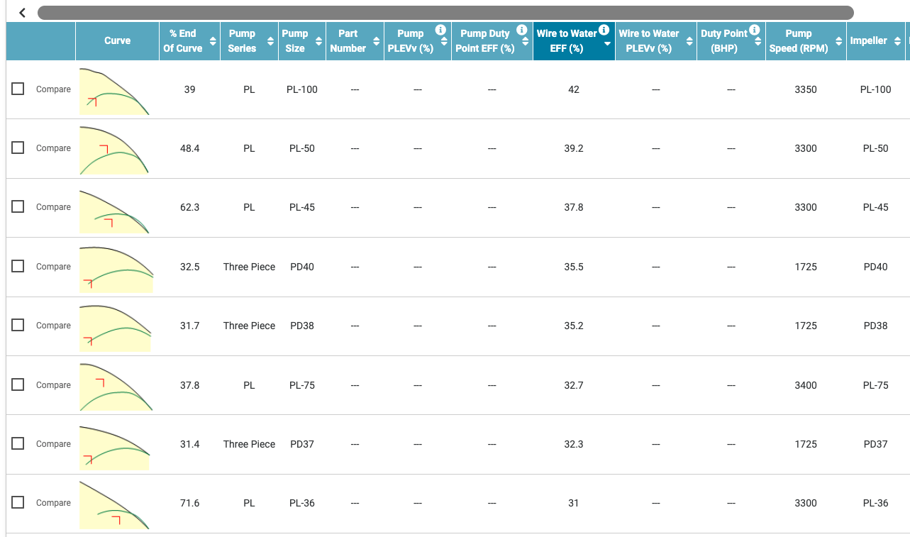
At the B&G site you can enter system spec and it shows pump options. I put 23 gpm at 10'. The PL 36 has a wire to water of 31% Where the black and green lines cross is the operating point OP with the numbers 23 gpm, 10' I entered.
The PL 45 is on a better spot on its curve so 37% wire to water efficiency.
Any Y strainers in the system?
Bob "hot rod" Rohr
trainer for Caleffi NA
Living the hydronic dream0 -
I do not have a Y-strainer, at least I haven't found one anywhere yet.
Is there a reason you picked the PL- line of circulators instead of the NRF- line?
0 -
I just entered your spec at the sizer program and it gives the selection. I'm not sure why no NRFs show up?
Performance is similar. The PLs are open frame motors, a bit more efficient compared to a wet rotor where the motor is sloshing in the fluid.
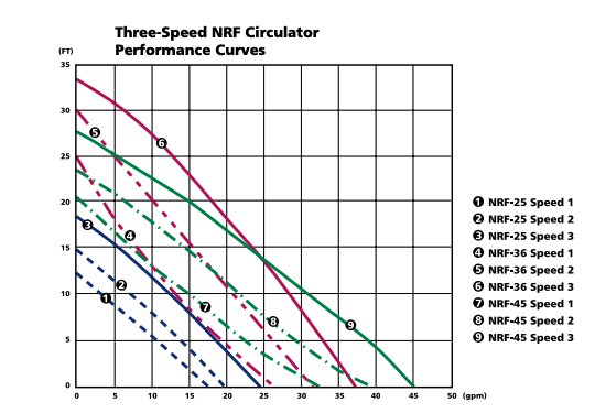
This pump curve chart below shows more of the NRF 3- speed selection, at various speeds.
If you want 23 gpm at 10', Speed 2 on the NRF 36 or NRF 45 is on the money. Since you want to work with the flange to flange spacing you have the 36 is the choice.
 Bob "hot rod" Rohr
trainer for Caleffi NA
Living the hydronic dream0 -
thanks a lot for your help! I will post again in a few days when I've got the 130F cartridge to describe my (short term) experiences.
0 -
check at www.dsireusa.org for ECM pump incentives in your area.
Here is an example from Mass Saves

Figure around 2200 hours of operation, using your kWh, see how the ECM matches the PSC for operating costs. With the rebates, if applicable, the numbers lean towards high efficiency
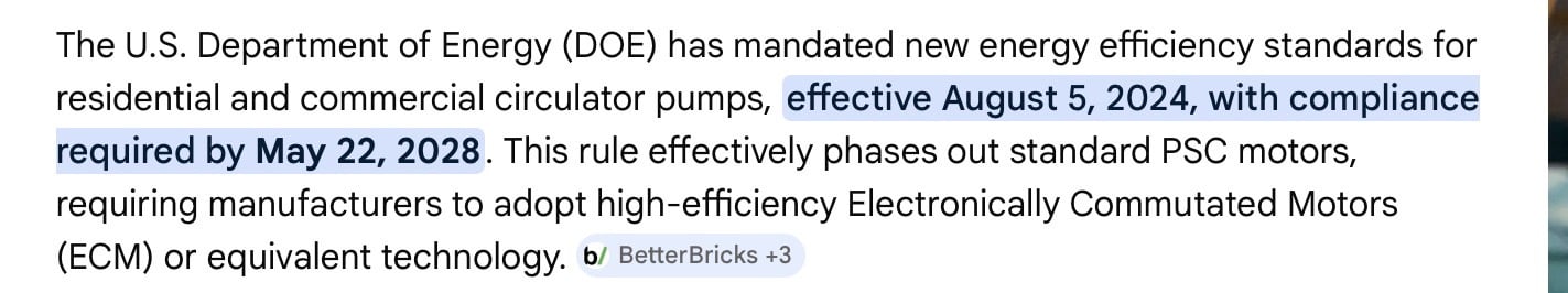
2028 is when all circs will be ECM, that is why you see the manufacturers stepping up their ECM product offerings. The U.S. may be one of the only places where PSC are still being used.
1/3 of all electrical energy consumed in the world spins a pump, of some sort. So reducing that consumption by at least 50% with ECM technology could be a big deal.
Although AI server farms, giving us instant answers like this, will gobble up that savings I imagine😏
 Bob "hot rod" Rohr
trainer for Caleffi NA
Living the hydronic dream0 -
We have two Weil Mclain WGO-5 boilers running at 1.2 gph (oil) input each, heating two gravity conversion systems with original cast iron radiators in a 4-unit condo building. We do not have bypasses, so our boilers run like yours did before you added the bypass, ie cold start, high water volume, and low supply and return temps. Typical supply temps <140, and typical return temps <120.
I've experimented with different flow rates through both systems by adding a variable speed control to each of the Taco 007 pumps, so that I can run anywhere from 10 gpm to about 17 gpm (max) through each system. Varying the flow rate will change the delta T as you would expect, but it has virtually no effect on radiator balance. All heat more or less equally, regardless of gpm.
And remember, these gravity conversion systems were piped and balanced to heat evenly even at the very low flow rates induced by gravity. Yes, later modifications (orifices installed in some valves, for example) may have changed the balancing somewhat, but I have a hard time imagining a scenario where we would have some radiators cold and others very hot, as you say, unless there was some other factor like air in some radiators. In our case, I can cut our flow rate almost in half, with no noticeable effect on radiator balancing. The only way I can get a drastic difference in radiator outputs (some cold, some hot) is by getting air in some radiators, thereby totally stopping flow through those rads.
So at the risk of asking the obvious, are you sure you didn't get some air trapped in the system when installing the Caleffi, which is now contributing to low flow/cold rads?
 1
1 -
it’s a fair question @jesmed1. I have visited practically every radiator with my air bleed key many times. There are a couple where the bleed valve is damaged or inaccessible but by and large I’m not encountering any air. Importantly, many of the cold radiators have functioning and accessible bleed valves and all I get out of them when bleeding is cold water. So I don’t think it’s air, at least in most cases. Even on the cold radiators where the valve is inaccessible or damaged, it’s not like the bottom of the radiator is hot and the top is cold. It’s cold from the supply pipe up.
0 -
It's possible to have air in the system that doesn't come out with "normal" bleeding. We had one radiator that for some reason bled only water when I tried to bleed it, and yet still wouldn't heat. I called our heating company to see if they could sort it out. The guy took a 5 gallon bucket to the bleeder, opened it all the way, and filled almost half the bucket with bleed water. Along the way, a massive amount of air came out. I just hadn't bled enough water to get to the air pocket. I still don't quite understand where that air was hiding, but evidently it wasn't at the top of the radiator. Maybe it was in a horizontal run of pipe leading to the riser.
One simple way to check your system is to fully close the manual bypass valve and let the boiler run just like it used to, with no bypass. If all rads heat normally, you know there's no air. But if the rads still don't heat evenly, you'll know which ones are air-bound.
0 -
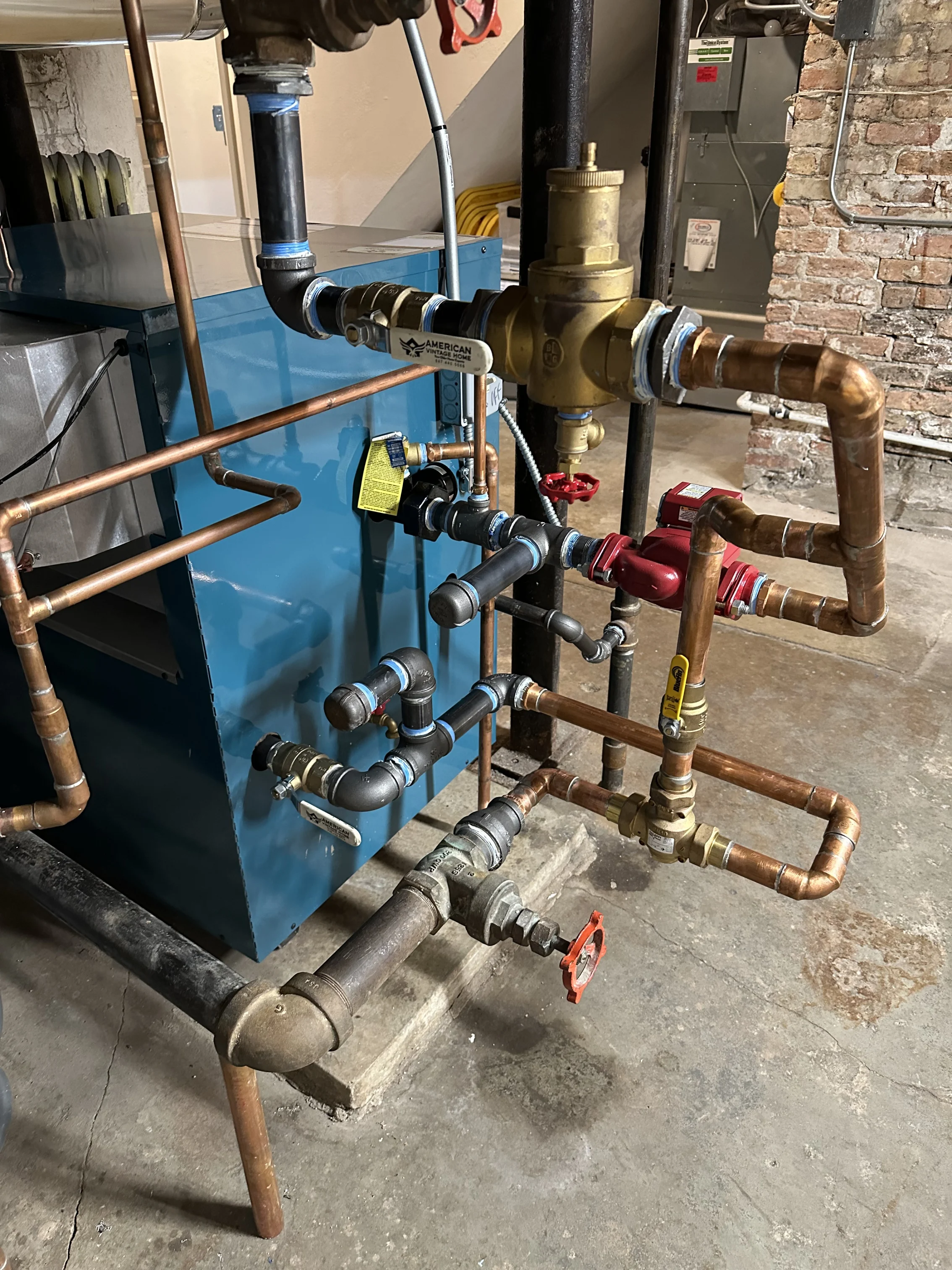
I don’t know if it’s easily visible in the pictures I posed above, but my bypass cannot be isolated. It’s something I wish I had thought to ask for…
I will give long bleeds a try at some of these colder radiators. Physically what do you think would be going on there? The air is stuck at the top of some sections, but not all? I can’t visualize a situation in my head where the supply pipe is cold and the problem is air, but I’m still a novice here.
0 -
I'm not an expert either, but I do know from experience with our system that air anywhere in a radiator loop will prevent flow through the entire loop, meaning the supply pipe will stay just as cold as the radiator. There are two radiators in our building where the supply and return pipes remain cold because the owner of that condo isn't interested in bleeding her radiators, so those entire loops stay cold. I can walk through the basement and feel each supply takeoff, and when I find a cold one, I know there's air in that loop.
If the boiler runs long enough, eventually some gravity circulation will occur inside the supply riser, so the supply riser eventually gets warm, but not because there's any flow through the radiator. It's just warm water going up one side of the riser, and cold water going down on the other side of the riser. And the return remains cold.
My only guess at what happened with the air-bound radiator I mentioned is that there was an air pocket in the horizontal pipe in the basement that takes the water from the supply main and feeds it into the vertical riser. And the guy who bled that rad had to flow enough water, fast enough, through the bleeder to force that air pocket to move out of the horizontal pipe, up through the riser, and into the rad where it bubbled up to the bleeder. I can't say for sure that's what happened, but it's the only explanation that makes sense to me.
0 -
if you look at piping examples of gravity systems the piping always slopes up to the radiators. This also helps the purging as the air rises into the top of the pipe and up into radiator , any droops or low points in the piping, or changes that created high points will make it much harder to purge.
With large diameter pipe you would need a substantial gpm. GEO loop field pump carts are generally 35 gpm and up.
I met a GEO looper in Iowa at a training and he bought a used fire truck to carry water and provide plenty of pump capacity for even a field of 2” loops
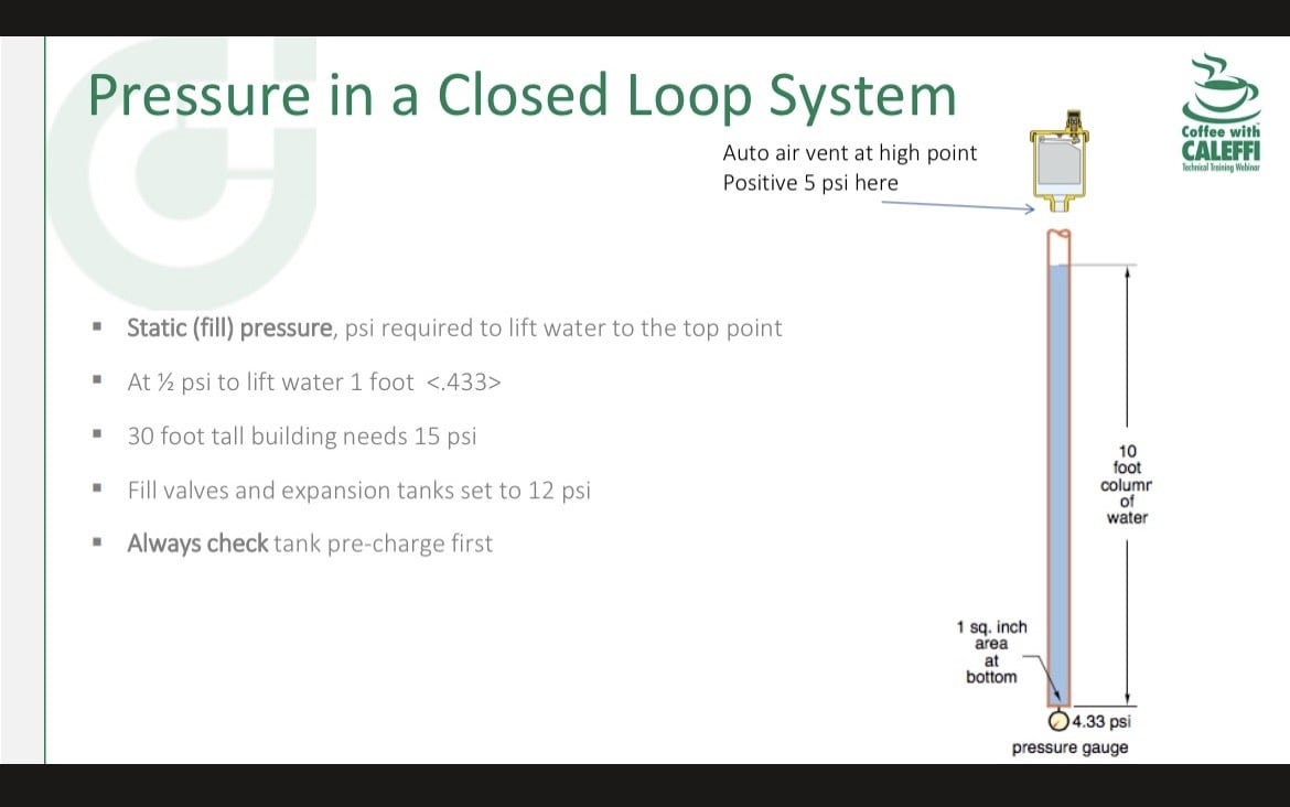
Boosting fill pressure is another trick to help expel air, you always want 5 psi at the highest point in the system. Boosting fill for a few hours to maybe 20- 25 psi basically squeezes the bubbles smaller and can assist the bubbles to move with the flow.
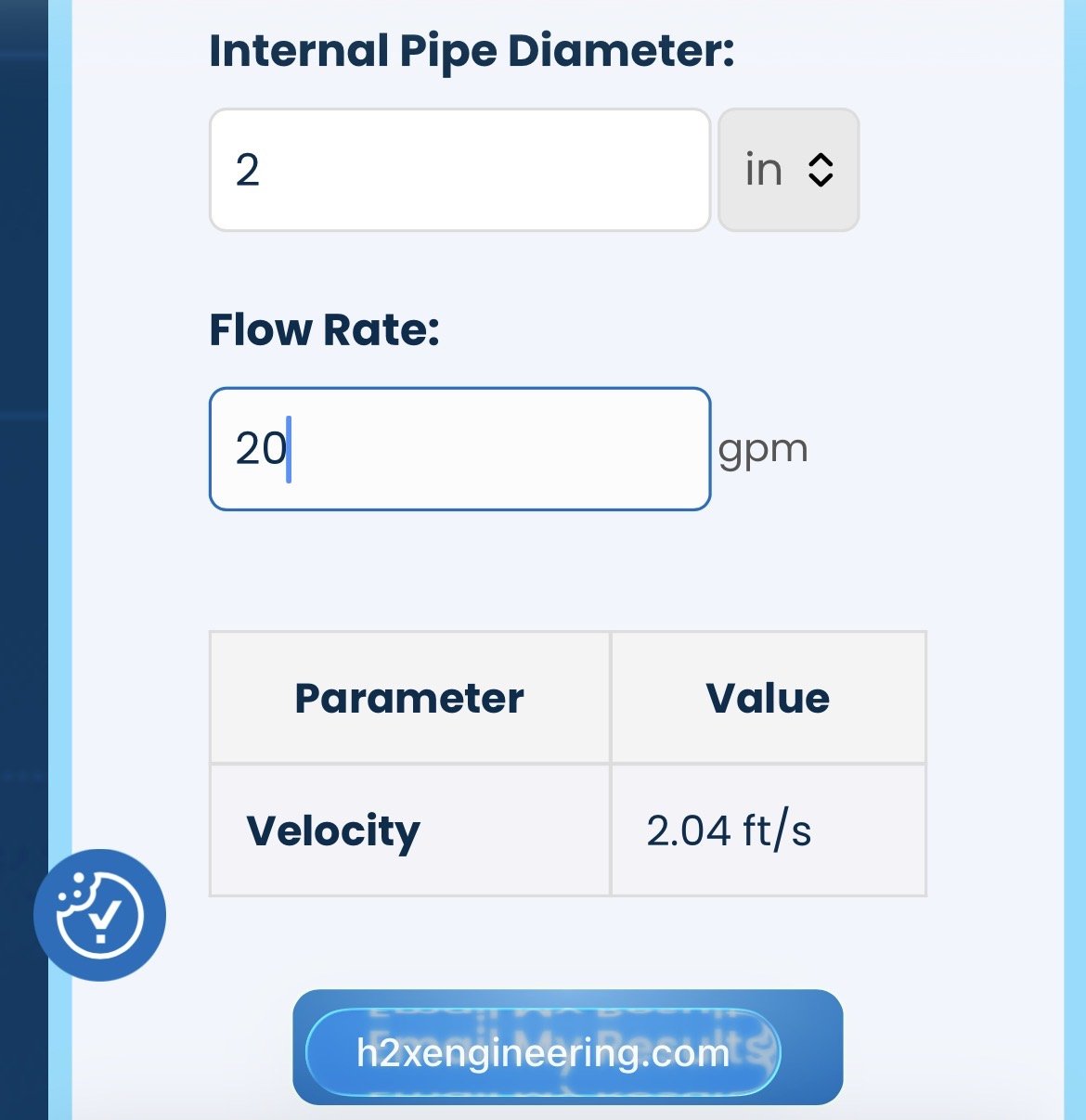
You need 2 fps velocity for air to move along with the water. In 2” pipe you need about 20 gpm. Here is an online calculator for gpm/ fps calculation
 Bob "hot rod" Rohr
trainer for Caleffi NA
Living the hydronic dream 1
1 -
Another option is to see if you have shutoff valves where the original gravity conversion pipes transition to your newer near-boiler piping, and close off all the supply branch shutoffs except one. When the boiler runs, all flow will be forced into the one open branch, increasing the gpm to that branch and hopefully moving any air pockets. Obviously you'd only do this with the branches that aren't heating. Then try bleeding the cold rads on that branch again.
In our gravity conversion system we have 3 main branches coming off the near-boiler piping, with valves at each transition, so if needed I could shut off 2 of them and force all flow through the other one. Unfortunately I didn't know enough at the time to try that method with the one air-bound radiator I mentioned.
As @hot_rod said, our gravity conversion pipes are pitched slightly up, at about 1/4 inch per foot, including those leading to our "problem" rad. So in theory, the air pocket should have naturally migrated up into the radiator, but for some unknown reason, I couldn't get it out with the typical slow trickle flow rate that I'm used to bleeding with.
0 -
@jesmed1 and @hot_rod wanted to share an update on the air question (130F cartridge still not here). I have bled a bunch of radiators without much to show for it except there is one that is (a) always cold and (b) always has a good 15-30s of air before I get any water. I've done this 3 or 4 times since my messages earlier this week.
What is unique about this radiator is that it is probably the furthest from the boiler, in the physical sense, it might be at the highest point in the house, or close to it, it is on its own tee off the main supply/return lines, there are no other radiators on this tee, and this is the very first tee. The piping for this radiator is smaller than all the other supply/return piping (I'm guessing 1 or maybe 1 1/4).
Is there anything I should infer about this fact? Does it help diagnose my balancing or flow problems in any useful way? I'm guessing not, but thought I would share anyway!
Thanks in advance for any of your ideas.
0 -
How high above the boiler is that radiator, approximately? What is the pressure on the boiler gauge?
You want at least 5 psi at the top of the upper radiator. On problem air systems you can raise the fill to 28 psi and try another purge. That helps push problem air out, sometimes. Reduce the pressure back down after this method.
There are other methods for a power purge if the boiler could be isolate, using 30- 45 psi right from a garden hose. Hook a bleed hose onto the problem radiator and let it rip for 10 minutes.
IF it is air locked you need flow, pressure, or both to push that air lock out.
OIn long loops or large diameter piping a tech will often use a purge cart, high gpm flow.
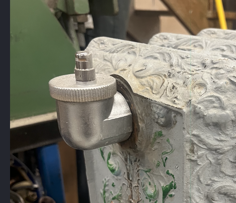
Got a pic of that problem radiator? Maybe you lower system pressure and add a better, higher flow valve at that radiator for the purge. Even a 1/8 or 1/4" mini ball valve will flow better that a coin bleeder.
Here is a portabl;e "test" radiator in my shop. When I fill it for flow tests I open that mini ball valve and it purges quickly and completely.
 Bob "hot rod" Rohr
trainer for Caleffi NA
Living the hydronic dream0 -
@tcovert83 said "there is one that is (a) always cold and (b) always has a good 15-30s of air before I get any water. I've done this 3 or 4 times…"
OK, so you've bled this rad 4 times and every time got 15-30 seconds of air? Times 4, that's 1-2 minutes worth of air, and the fact that you keep having to bleed and get more air every time means there's a lot of air in your system, and yes that's why that rad is cold.
Our problem rad I mentioned earlier is similar to yours: farthest from the boiler, and at the highest point (2nd floor). I had the oil company guy bleed it several years ago (that's when he filled half of a 5-gallon bucket getting all the air out). It then heated properly for a while, but then I opened the system to make some upgrades (adding an Airtrol tank fitting, and then later removing the old expansion tank and replacing it with a diaphragm tank) some air got back into the system, ended up in that rad again, and the owner of that unit doesn't want to bleed it again. So I just leave it cold knowing it's full of air and I can't do anything about it.
What's different about your problem rad is you say it's the very first tee off the supply from the boiler, which is odd, because you also say it's the farthest rad from the boiler. Normally it would tee off near the end of the supply main, not the beginning. The fact that it tees off right after the boiler means that the large air pockets you introduce by opening the system up are probably going right into that rad.
You might want to consider putting an automatic float-type air vent like the Caleffi Minical on that rad. I have these on our boilers and they work well. Some pros don't recommend putting auto air vents on rads because they can leak eventually, but this version of the Caleffi has hygroscopic cellulose washers inside the vent cap that expand when wet and thus choke off any leaks before they drip onto the floor.
https://www.supplyhouse.com/Caleffi-502043A-MINICAL-Automatic-Air-Vent-w-Hygroscopic-Safety-Air-Vent-Cap-1-2-NPT?_br_psugg_q=caleffi+air+ventThese come in different pipe thread sizes, so you'd have to be sure to get the right pipe size to fit the rad. You might also need to install an elbow with a nipple to get the vent vertical.
0 -
Sadly we don't offer this vent in North America. It is a 1" vent with a float and hydroscopic cap. So very fast venting with the two stop features.
Caleffi #504 Aercal in 1/2, 3/4, and 1" rh or lh thread.
 Bob "hot rod" Rohr
trainer for Caleffi NA
Living the hydronic dream1 -
Seems odd Caleffi wouldn't offer the right angle version in North America when there are so many old cast iron radiators around here…
0 -
Well air in the system is something you want to deal with, even though it may not be causing the issue. The top radiator in my house routinely would accumulate air - like 20 or 30 seconds worth. I fixed that by a) installing a B&G, sorry Xylem, IAS (inline air separator), and b) installing Airtrols on my dual compression tanks.
As for the cold radiator, all I have to offer is that in my zone1 there are three free-standing radiators on the first floor piped with 1-1/2" and 14' of 9" cast iron baseboard in the basement piped in 3/4". To get ANY heat to the basement radiators I had to throttle back the first floor radiators significantly, using the valve on the radiators. I think you said you didn't want to mess with those valves during heating season.
You say this is a new problem. What changed is the Caleffi valve. I think with the 140F element the valve never opens fully resulting in reduced flow to the system, that plus the air might be enough to explain the cold radiator.
—Eric
0 -
Air is definitely still a mystery. I think the installer may have left the air eliminator in the closed position, or perhaps too tight, and so I've tried opening it until just before water comes out. But so far the radiator I've described still has a ton of air every couple days.
While I'm (still!) waiting on my new valve cartridge, I have been thinking more about my pumping situation. I've taken many measurements of the system return, mixed return, and boiler supply temperatures during the beginning, middle and end of heating calls, and I've yet to see boiler delta T (boiler supply minus mixed return) budge from the high 20s to mid 30s range. Since my boiler is 235,000 btu/hr out, I think this means my flow is like 13-16 gpm, which is consistent with the valve producing a ton of resistance against my circulator (an NRF-33). As @hot_rod suggested last week, I could get a bigger circulator, but I've also been wondering whether the right move here would be to spend a little more and get a primary/secondary setup, so that I can use a sensible circulator to move water to my radiators instead of ramming things through with an oversized circulator. It seems that if I did that, I would probably get higher flow in the radiator loop than in the boiler loop, and that would also have the side benefit of delivering lower temperature water to all of the radiators, instead of high temperature water to some and cold water to others. As I mentioned last week, the house was pleasant with lower temperature water prior to the valve install, and so I'm wondering if a primary/secondary loop would bring me back to that situation.
The piping I am thinking about is roughly Figure 4 here, except that I wouldn't have a mixing valve on the radiator side. https://digital.bnpengage.com/ebook-john-siegenthalers-top-25-0322/02-the-dos-and-donts-of-3-way-thermostatic-valves/article-2/
Experts, what do you think? am I making things too complicated?
0 -
"a ton of air every couple days" suggests something is wrong. It looks like your setup is "pumping away" from the expansion tank, which is correct. But maybe your pressure is set too low and you're pulling a vacuum in that problem radiator? What is your static water pressure, and are you sure the gauge is correct? Also, what is the height of the radiator?
PS—the link doesn't work.
0 -
How would P/S change the flow resistance through the mix valve?
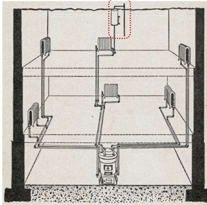
If, which I doubt, the flow resistance is in the valve you need a pump sized to overcome that. Then a second pump sized to the distribution, it looks like this. So 23 gpm through the boiler with maybe 5' head.
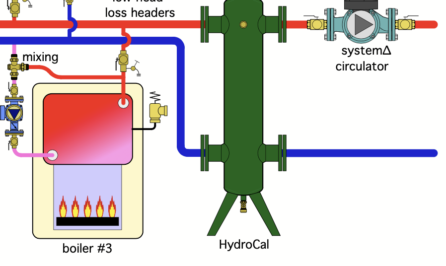
235,000 btu/hr at 20 delta would need 23 gpm. That would be 4.23' head. If you run a wider delta, say 30∆ then pumping head drops.
The pump you have should be close, maybe it never gets to exactly a 20∆, but is that an issue if all the radiators are getting warm enough to do the job?
Something else is going on in the system causing inadequate flow, or air locks I suspect.
Bob "hot rod" Rohr
trainer for Caleffi NA
Living the hydronic dream0 -
sorry about that, here is a corrected link:
static pressure is in the high teens: the boiler gauge reads like 17-18, and the gauge on the fill valve reads about 16.
the problem radiator is about 18-20 ft above where the boiler sits, though its horizontally maybe 50ft away?
to be clear, there are many problem radiators (in the sense that there are still a bunch of cold ones), but the one in question is the one which bleeds a bunch of air every day or so. The other cold radiators bleed water.
Maybe an additional useful fact: most of the cold radiators that are not the one in question are all at the end of the same tee. The first 4 radiators on this tee are plenty warm, and the last 4 are basically all cold. I have tried bleeding all of the cold ones and they too just spit out a stream of cold water into my face…
0 -
So for a 20 foot high radiator where you want to maintain at least 5 psi, your system pressure would be (20/2.4 + 5) = 13 psi. You say you have 16-18 psi, which should be enough, but you evidently still have a large air problem. I would try adding maybe 5 psi more air (not water) to the expansion tank. Obviously you want to keep an eye on the pressure when the system is hot in order not to get too close to the 30 psi relief valve setting. Our SX-40V is big enough that our pressure increase from cold to hot is only 5 psi, so we could safely run 20 psi cold and 25 psi hot if we needed to.
But in the bigger picture, even without a circulator, all gravity conversion radiators should get hot. Unless someone repiped the system incorrectly, those old guys knew how to size the pipes correctly so that gravity did the work and hot water reached all the radiators. So if those are still the original pipes, either you have air in that loop that you still haven't gotten out, or there's some physical blockage like pieces of old washers stuck in valves, etc.
What size is the pipe that tees off the supply near the boiler and then feeds all these cold radiators? Where our gravity conversion supply pipe feed 8 radiators, the supply pipe is 2-1/2" nominal, then steps down gradually after subsequent radiator takeoffs.
0 -
Here's a suggestion before you forge ahead….
Remove the thermostatic element and let the system run to see if the behavior returns to the way it used to be. The only restriction then would be the water going through the body of the valve.
Eric
0 -
thanks so much for all your thinking!
@hot_rod I don't think P/S changes resistance through the flow valve. I am thinking that there is always going to be some (or lots) of resistance due to the valve since I've got so much in the way of radiator mass and I doubt there will many many heat calls where the system return temps allow the bypass to be fully closed. this made me think (perhaps aspirationally?) that P/S would let me flow more to the radiators without pushing harder on the valve. but maybe I am wrong?
I've been thinking the resistance is the valve because prior to it the NRF-33 was pushing probably 30 gpm.
when you say I need a pump sized to overcome that, you mean the desirable operation of my setup would have delta T through the boiler of 20F (or so) and not the 35-40F I am currently seeing? I guess I had taken it for granted that the delta T through the boiler would be large, and that P/S would let me have a more sensible delta T through the radiators. but I am still learning, so let me know what I've got wrong here.
@EricPeterson are you saying I can just pull the cartridge out and let the system run without any cartridge at all? I guess after screwing the bottom cap back on?
@jesmed1 how does one add air to the expansion tank? I can find YouTube videos describing this procedure for domestic hot water. Is it basically the same?
the pipes are honestly quite large. for the problem radiator (which is the first tee, and its the only radiator on the tee) I think its 1.5 inch steel pipe. for the line I described where the first half is hot and the second half is cold, its huge - I think 3 inches? it does step down somewhat (first to 2.5, and then to 2). the individual radiator tees all appear to be 1.5.
0 -
@tcovert83 yes on the valve, but I am assuming you have isolation valves sufficient to disable the bypass route for the water.
Eric
0 -
@EricPeterson unfortunately I did not get piping that is sufficient to totally bypass the bypass (kicking myself for not asking for this…)
0 -
It sounds like the piping is the original large-diameter gravity piping, which means there's very little pressure loss in the pipes due to friction, so the water should circulate freely and easily through the pipes with minimal pump pressure. So the piping isn't your problem, it's a combination of air and possibly reduced flow due to the thermostatic bypass valve.
So IMHO, you have two problems to solve: (1) where/why is the air getting in, and (2) a flow problem that may or may not be related to #1. But until you solve the air problem, changing the bypass cartridge isn't going to fix the cold radiators.
If the system was working fine and all radiators were getting hot before the bypass was installed, that means air wasn't getting into the system before. Something changed with the bypass installation that is now allowing ongoing "sucking" of a lot of air into the system. Either that or there was a ton of air introduced when the bypass was installed, and now it's coming out a little at a time through the problem radiator, and you haven't gotten it all out yet.
I'm not an expert, so I would ask the experts like @EdTheHeaterMan and others if it's possible that air might be getting sucked in somewhere. But it sounds like your system pressure is high enough to prevent a negative pressure that would suck air in through, say, a radiator valve.
You can add air to the expansion tank by unscrewing the black plastic cap near the perimeter of the top of the tank. That hides a Schrader (bicycle tire) valve through which you can add pressure. But don't do that until you know how much pressure increase there is when the system goes from cold to hot. In our case, it's 5 psi, so for my system, I wouldn't raise our cold pressure above 20 psi in order to keep well below the 30 psi relief valve threshold when hot. Depending on your tank size, you might have more of an increase when hot, so you may not have as much room to increase pressure.
We run 15 psi cold/20 psi hot, in a 2-story system like yours with boiler in the basement, and we don't have air problems. You have similar height and pressure, so either there's still residual air in the system from the bypass install, or air is now being continually ingested in some unknown way.
0 -
@tcovert83 - Looking more closely at the picture you posted previously, it looks to me like you can run the boiler with the element removed. If you close all three valves - white, yellow, and red handles - you can remove the element.
Then if you open only the valves with white and red handles, leaving closed the valve with the yellow handle, it appear to me that the boiler will now operate in the previous manner, the only difference being that the return water is passing (unimpeded by the element) through the valve body.
But please think this through to make sure I am not missing anything.
@hot_rod does this make sense to you?
Eric
 0
0 -
An update after a couple days with my "130F" cartridge:
(1) I never heard any of the whining that @EricPeterson mentioned when I had the 140F valve cartridge. Now I hear about 2 minutes of it at the beginning of a heating cycle. Any idea what might cause this? It does seem to go away once the valve opens a bit to the system return but it is loud enough to notice. Is there a chance I messed up the installation? I followed the steps in the instruction packet, as well as this video, very closely. I would love to make this go away if its possible… https://www.caleffi.com/en-us/blog/how-do-i-change-thermostat-boiler-protection-valve
(2) The mixed temperatures I am seeing with this valve cartridge are quite a bit lower than what I saw with my original setup. Before, I was seeing mixed temperatures (as measured by an IR pointed at the piece of pipe closest to the system inlet) of 130 - 145, with the mixed temperature reaching 130 only a few minutes after the boiler started. Now, I am seeing mixed temperatures that start at 100-110 and very slowly make their way into the mid to high 120s. I would say I get to about 120F within 30 minutes. I have not yet seen a measurement over 127F. Is this to be expected? I wonder if I somehow got the 115F cartridge by mistake. The packaging says "F29634 DN 25-32" on the first line and "55C - 130F" so its not ambiguous. I know @hot_rod has mentioned a few times in this thread and others that the 115F cartridge is probably fine for a modern gas CI boiler, but I thought I'd ask.
(3) The new valve cartridge, whatever temp it actually is, has indeed improved balance in the system, presumably by increasing the flow I'm delivering to the system. Not all of the cold radiators get warm, but a couple of them do. The "problem" radiator from a few posts up has even felt hot once or twice! At the end of a longer call for heat (before it got warm here!) I saw a system delta T (boiler minus system return) of about 35F, which is getting closer to what I was hoping for. At that point the return temp was 121F, the mixed input was 125F, and the boiler output was 156F. This was after about 2 hours of boiler operation.
I will probably still upgrade my circulator, but I thought I'd share my experiences.
0 -
@tcovert83 - there was quite a bit of discussion regarding the noise in this thread.
If you have the patience to wade through it maybe it will be helpful.
Eric
0 -
Thanks for sharing that @EricPeterson. Is it safe to summarize your findings about the whining noise and its solution as: during the cold start, when the bypass is fully open and the return port is closed, the single speed pump was pushing water fast enough through just the boiler and bypass loop to create noise, and you fixed this with an ECM which pumped slower during this phase?
If I've got this right, its sort of bad news for my plans to improve things via a more powerful circulator. In this brief boiler and bypass only phase, I estimate my current NRF-33 is pumping 20 gpm, and this steps down to about 14-15 gpm once the return port is open and the pump is exposed to the rest of my system head. However, I think I should be aiming for 20-23 gpm in order to get a delta T closer to 20 on my 235,000 btu/hr boiler, so one interpretation of these facts is that this noise would become permanent under a more powerful circulator, I think.
One part of this explanation and my experience that isn't identical to yours is that I only experienced this noise after replacing my 140F cartridge with the newer cartridge. It would seem that if high pumping against a short and lower head loop is the explanation for what I am experiencing now, I should have experienced it with the 140F valve too?
0 -
@tcovert83 - yes I would think the noise would have been there, and for longer, with the 140F.
I'm sure there's a solution out there for you. One might be using primary / secondary, with a low GPM circulator for the boiler loop, and the higher GPM one for the system. That's the solution I read about for these applications, but as @hot_rod has pointed out P/S alone doesn't solve the problem of low temp return water which you have fixed with the Caleffi.
Or maybe a variable speed circulator that speeds up with the water temp, if there is such a thing.
It would defeat the purpose to some degree, but what about a bypass to the bypass - meaning allow some water to go around the Caleffi just to lower the whining. Maybe just a trickle would be enough to solve the problem.
Obviously none of these is implementable without some repiping. But the heating season is almost over so that's a plus. If it were me I'd go for the P/S, especially if you have the room (and the budget).
Eric
0 -
Thanks @EricPeterson. I suppose the other confusing piece about this theory of the temporary whining/humming sound is that prior to even having the boiler protection valve, I never heard this sound. I would have thought that my system as a whole has less resistance than the valve itself (old gravity conversion with enormous pipes, etc) and so I think I was pumping even faster than 20 gpm back then, but obviously I didn't have direct measurement, only something approximate via noisy temperature readings and knowledge of the boiler output. My near-boiler piping was obviously a bit simpler then, too, so maybe there was less to hum? I am not sure.
In case you think this is useful information: when I had the 140F cartridge, I basically always heard swishing sounds, similar to what I hear when water goes down a drain. Not continuously, but say a few times a minute. Now I don't hear those sounds, but I do hear the whine/hum during the first 2 minutes.
I have a better temperature gauge on the way, and its going to be colder over the next few days. I'll try to take more careful temp measurements and report back what I am seeing.
0 -
are you sure you have 109% of the air out after you made the cartridge adjustment?
The valve should be silent in any position.
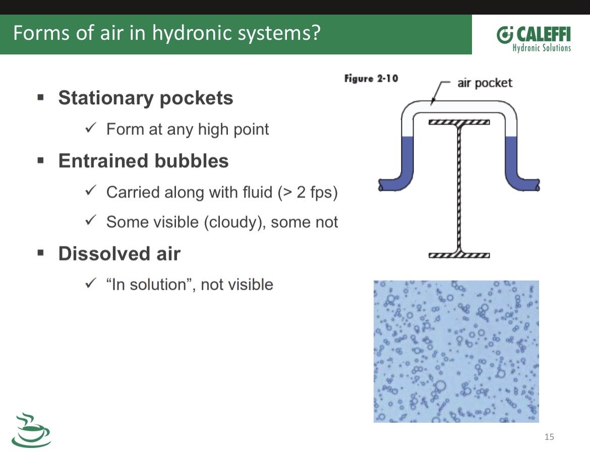
Swishing or sloshing can be an air symptom, any variety if noises actually from entrained air passing through a control valve
Bob "hot rod" Rohr
trainer for Caleffi NA
Living the hydronic dream0 -
I definitely have less air now after the cartridge change out, and I was careful to refill the system to pressure after doing so. Now I am not hearing any of the swishing I heard but I do hear that hum for the first 2 minutes.
0 -
@tcovert83 - I'm going to go way out on a limb here and suggest that before you do any further analysis or re-piping, you must first get all the air out of the system. As you continue to mention there being air in the system I think you need to get rid of all the air in order to have an apples to apples comparison.
Initially you said the house was evenly heated with the new boiler and the NRF-33. Then the trouble started with the installation of the Caleffi.
Since this is a converted gravity system, let's assume that the original installers piped it in such a way that there was even heat distribution throughout the system, with just gravity doing the work, by the proper selection of pipe sizes, without a circulator.
As for noise, looking at the pump curve for the NRF-33, when the Caleffi is closed to the system you are certainly going to get some noise since there is very low head so under those conditions the water velocity works out to be around 8 fps. So changing out to a circulator with more GPM will just make that situation worse since there will be noise if the fps exceeds 4 fps.
My 2 cents worth,
Eric0


Categories
- All Categories
- 87.6K THE MAIN WALL
- 3.3K A-C, Heat Pumps & Refrigeration
- 59 Biomass
- 429 Carbon Monoxide Awareness
- 124 Chimneys & Flues
- 2.2K Domestic Hot Water
- 5.9K Gas Heating
- 119 Geothermal
- 168 Indoor-Air Quality
- 3.8K Oil Heating
- 78 Pipe Deterioration
- 1K Plumbing
- 6.6K Radiant Heating
- 394 Solar
- 16K Strictly Steam
- 3.5K Thermostats and Controls
- 56 Water Quality
- 50 Industry Classes
- 50 Job Opportunities
- 18 Recall Announcements