Caleffi 280 Thermostatic Mixing Valve

Too bad it's not a drop-in replacement, I'll have to do some re-piping.
The pipe marked "Supply" is my system bypass, hot water from the boiler controlled by a ball valve.
So should I also pipe in a bypass around this valve in case there are problems?
For example suppose it got stuck and no return water was getting through.
Or are these valves highly reliable?

Comments
-
Hot Rod knows the Product best, (but hopefully he's sleeping right now) but I can tell you as an installer Caleffi Products are Numere Uno! Very high quality. Yes that's annoying...For many Years I used the ESBE by Danfoss (excellent)mixing valves which fell right in the way you wanted. I primarily use Taco (Also excellent) now and the ports are different so you gotta repipe them. Mad Dog 🐕
 1
1 -
Ni
need, in harm in having a bypass and service valves
Water quality us the killer if any thermostatic valveBob "hot rod" Rohr
trainer for Caleffi NA
Living the hydronic dream0 -
The Caleffi valve is piped in and I just ran the system using it for the first time.
I'm using a 140F element in the valve.
Initially I detected a slight whine in the circulator, when the boiler was completely shut off from return water. This went away once the valve started to open up and started mixing in return water.
I have a gauge on the return to the boiler and also on the supply to the system. It was a little odd to see the return temperature at 140F being above the supply. The supply temperature slowly rose, but I was surprised to see the return temperature also rise, I would have thought it would stay closer to 140F.
Heating system is just begun so I will have lots more observation time soon.
Eric0 -
@EricPeterson We have two oil boilers that should have had bypasses plumbed in when they were installed 25+ years ago, but weren't. We'll need to have bypasses installed when we replace those boilers eventually. Thanks for posting your install. I'd be interested to hear updates from you about how it's working.
Also, what is your boiler net output BTU/hr, and how long after startup does it take for the valve to start opening to allow return water in?0 -
@EricPeterson I have one of those on order now, hope to get it next week. I also got a DirtMAg and I am getting my city water tested to see about a water filter. I'll be piping it into the system with ball valves & unions for service. Interested to hear how it works for you. Where is your pump in relation to the valve?0
-
@jesmed1 - the net output is 153 MBH. I can't find it in the manual but I think the boiler holds around 5 gallons of water. So when the valve is cycling all the heated water back to the return, it heats up pretty quickly, in a minute or two if I recall correctly, and then the valve opens to start mixing in the return water.
I'll know better when I install some temperature gauges in the valve wells, those gauges are on backorder.
For now I can measure the temperature in just three places:- the return pipe into the boiler
- the supply pipe to the system (which is after the bypass to the valve)
- the supply pipe from the boiler
Eric0 - the return pipe into the boiler
-
OK, thanks. Keep us posted.EricPeterson said:@jesmed1 - the net output is 153 MBH. I can't find it in the manual but I think the boiler holds around 5 gallons of water. So when the valve is cycling all the heated water back to the return, it heats up pretty quickly, in a minute or two if I recall correctly, and then the valve opens to start mixing in the return water.
Eric
0 -
Interestingly enough, I found this online calculator to determine the amount of time needed to raise 5 gallons of water from 68F to 140 F for my boiler rated at 153 MBH.
The result I got from the calculator was 2 minutes, which is about what I had estimated.
This is the time it takes before the boiler starts mixing in the return water.
So far I am very impressed with the performance of this valve. It provides a simple mechanism to eliminate low return temperatures for my boiler.
After a couple of test runs yesterday where I played stationary engineer and monitored its operation, I just let it run unattended overnight and woke up to a warm house.
The other change I made to my system was to re-pipe the compression tank, install an Airtrol ATF-12, and properly install the IAS air separator (it was installed backwards before). I hope this helps reduce air in my system over time. I found the install procedure for the ATF-12 wanting, and I was not that impressed with the instructions. More on that later.
Eric0 -
I ended up going with a 130 element on the one I had on my wood gasification boiler. I could hear the variable speed inducer fan revving down before the 140° valve hit its 158 bypass shutoff point.
My control was a metric version with an 80C limit temperature.
With the 130 + 18° differential it would shut off the bypass completely at 148.
I actually think for a gas fired cast boiler the 115° cartridge would be adequate. 115 + 18= 133° shut off of the return. So it would close the bypass 100% a little quicker. See if yours works okay with the 140, the boiler heats quick enough on cold start. It's probably only on the first start up of the season when everything is cold. Once you are running more often it should not have a lag.Bob "hot rod" Rohr
trainer for Caleffi NA
Living the hydronic dream0 -
@hot_rod - yes I wondered about that when I bought the valve, especially since my boiler (Burnham ES2) claims that 110F is an acceptable return water temperature.
Is it simple to swap out the valve? I installed isolation ball valves around the Caleffi so that will make it easier.
Another consideration is that if I ever spring for outdoor reset, the 140F would probably be too high for that (OR) to be effective.
For the time being I'll stick with the 140 and see how that works.
Eric0 -
It is just a little copper heater that goes inside, no need to change the valve. Good that you have iso valves, it will be a 10 minute job.
PM me your mailing address.Bob "hot rod" Rohr
trainer for Caleffi NA
Living the hydronic dream0 -
0
-
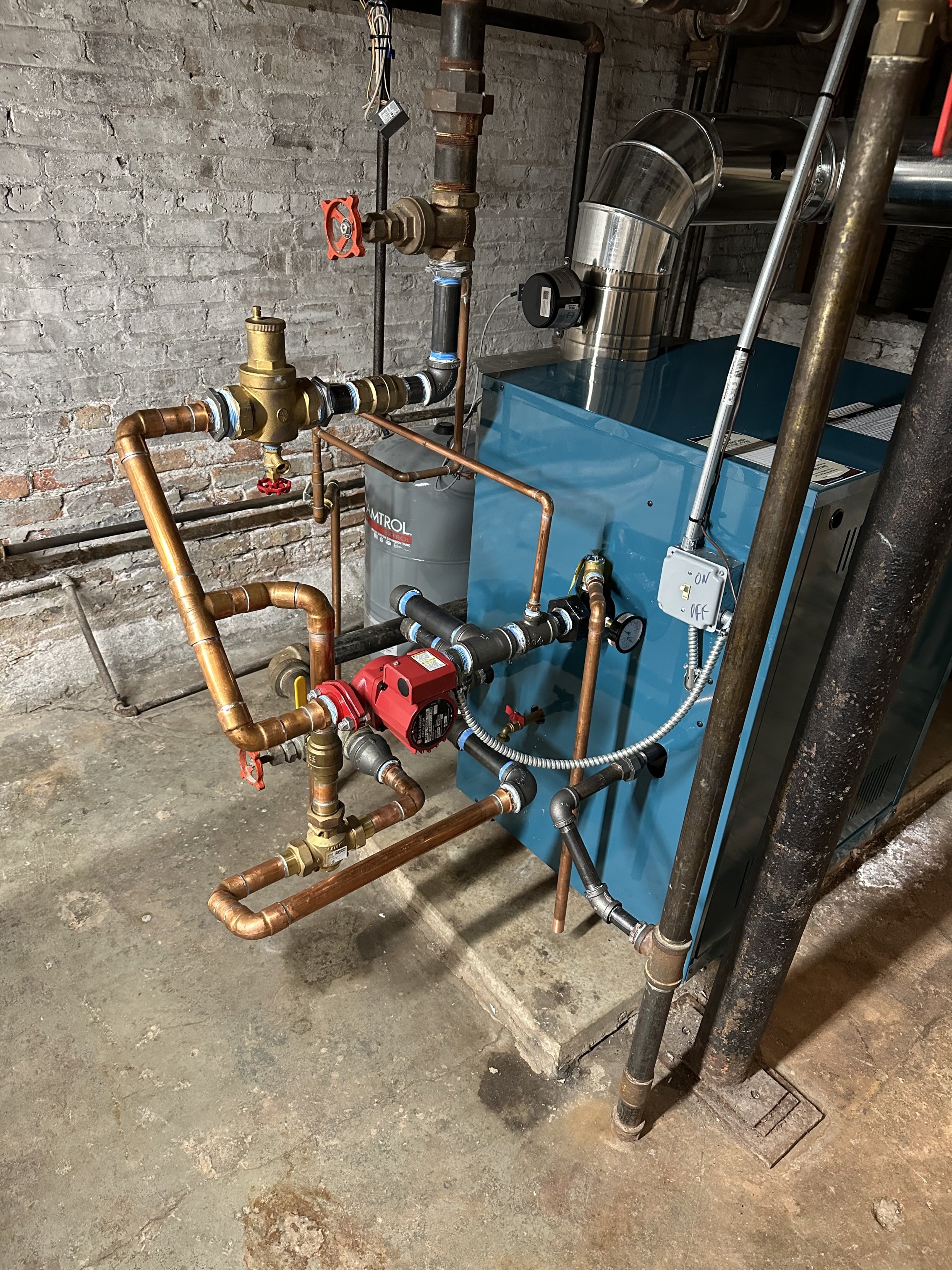
Here's before and after photos.
The before photo also shows the Series 100 that was replaced in 2013.
The after photo has the Caleffi valve installed. I still have to hook up the water supply.
Eric Peterson

0 -
Good that you have access to the cap at the bottom of the valve, that is where you change to a different temperature sensor.
Remove slowly so you keep track of the parts and the order they go back in.Bob "hot rod" Rohr
trainer for Caleffi NA
Living the hydronic dream0 -
@hot_rod - yeah I piped it so I had easy access to the valve for any maintenance or issues.
It seems very solid and well made.
The only issue as I mentioned before was while the valve is closed and water is circulating in a tight loop through the boiler, there is a slight whining from the circulator. That stops once the valve starts opening up.
Maybe if I had piped it with two circulators that noise would not occur but I have not thought that through.
I talked to a tech at Caleffi who was certain that with my converted gravity system, the valve would work with a single circulator, so that is the way I went as I prefer to keep the system as simple as possible,
Eric0 -
is it a multi speed circ. Those gravity systems do not need much pumped flow the experts tell me. As long as the boiler is getting adequate flow, slowdown the speed.
That valve never closed both ports. As one closes the other opens the same amount. So there should never be flow restriction regardless of which position the valve is in.
With the lower temperature sensor, the valve will fully open to the system quicker, see if that changes the noise.Bob "hot rod" Rohr
trainer for Caleffi NA
Living the hydronic dream0 -
@hot_rod - thanks for the feedback.
As for the flow, I understand that the Caleffi valve does not close both ports. The noise occurs when the valve is closed to the system, so the flow is restricted to about 10 feet of near-boiler piping, with water from the boiler supply passing through the air separator, circulator, Caleffi valve, then back to the boiler.
As I indicated before, when the Caleffi valve is closed to the system it takes about 2 minutes for the water temperature to rise from 65° to 140° when the valve starts to open. This time will be even shorter with a 115° thermostatic element.
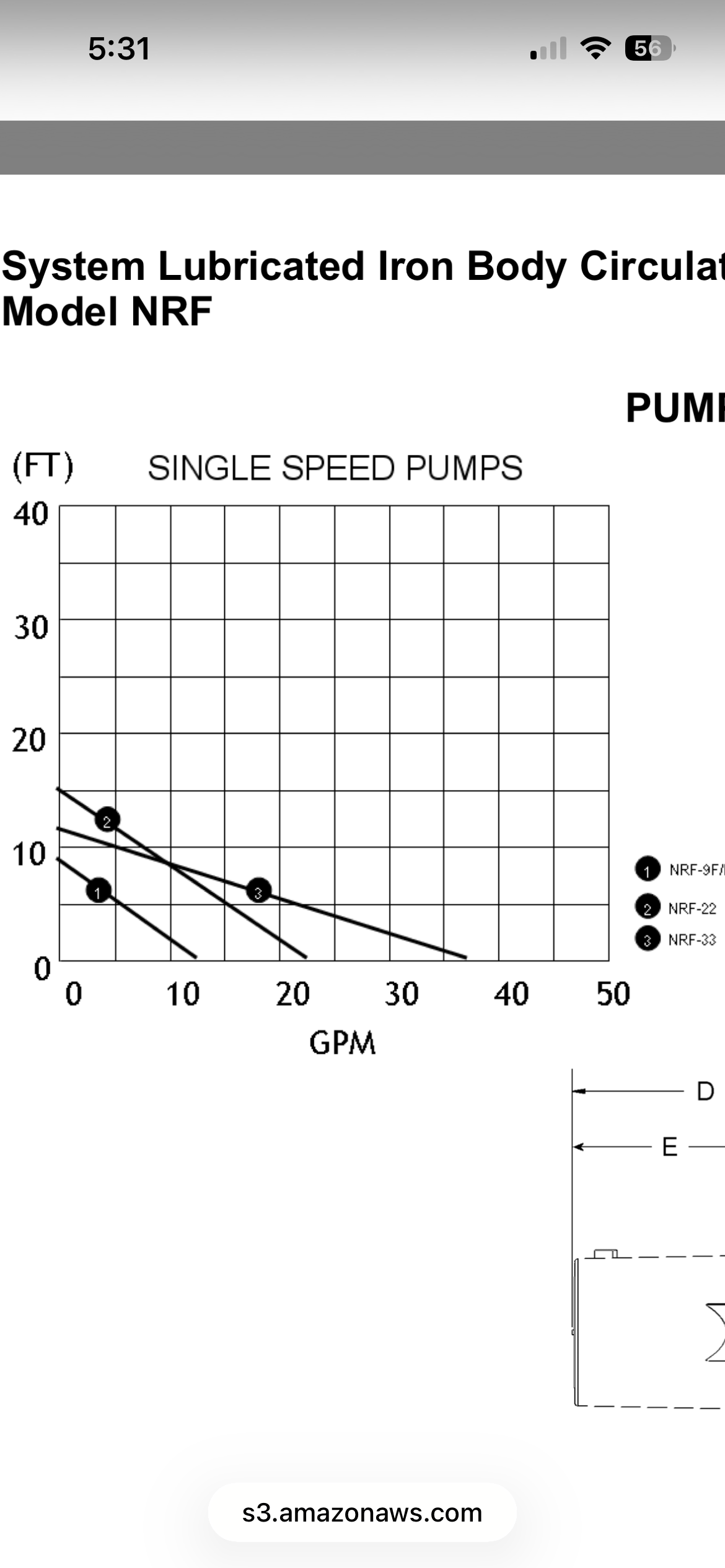
The circulator is a NRF-22, so not a multi-speed circulator. I would consider a different circulator if the current setup is damaging to the NRF-22.
I piped in a ball valve from the system directly to the boiler return and this valve is closed so that the return is instead diverted to the Caleffi valve.
I could try running the system with this ball valve slightly open to see if that addresses the startup noise
issue.
Eric Peterson0 -
I can't imagine you have more than a few feet of had with that large boiler piping and cast boiler, so you are moving some high flow across the valve.
I don't have a lot of gravity conversion experience , the pros hear claim a slow pump speed to mimic the gravity flow. The B&G 100's had a nice curve for that, or a three speed circ that slows more than the nerf 22.
Hissing noise is generally a sign of an over pumped condition.Bob "hot rod" Rohr
trainer for Caleffi NA
Living the hydronic dream0 -
@hot_rod - you're right in that the Series 100 pump curve is a better match for my system, which I've calculated in the past as:
- EDR: 908
- GPM: 24-25
- Head: 3-3.5
My best best would probably be to go with the NRF-25!
Eric Peterson0 - EDR: 908
-
A system like yours want gpm, but low head. The NRF 25 come closest to that. Plus you have some adjustability with the speed selector.
If you have the desire and $$ the Grundfos Alpha 15-58 has some very customizable features and would use 1/2 the electrical energy.
Bob "hot rod" Rohr
trainer for Caleffi NA
Living the hydronic dream0 -
As for the circulator, there are two scenarios here:
- First is cold startup when the circulator is running a tight loop through the boiler, valve, and near-boiler piping.
- Second is when the valve has started to open or is fully open and water is flowing through the system.
Once water is flowing through the system, the NRF-22 has worked fine for me. Based on the pump curve charts there are other models whose specs are a better match for my system, but at this point I see no reason to make any changes.
As for the valve, I am very satisfied with its operation. I have been thinking about installing this type of valve for years, and am very glad that I finally got around to it. Initially I was thinking of the Danfoss valve, but the service support I've received from Caleffi has been top-notch:- during the planning process, I was able to speak with a tech named Matt at Caleffi who assured me that the valve would work properly when piped with a single circulator. Turns out he was right.
- on the Wall, @hot_rod has been extremely helpful with comments and suggestions relating to the installation.
- if it were to fail in a way that the valve remained closed, then no heated water would get out to the system. This would be a real problem in sub-freezing temperatures as it would put radiators at the risk of freezing.
- if it were to fail and remain open, the the thermal protection would be gone, but the system would still get heated water, so this would be an acceptable failure mode.
So if we were to be gone, I would set that bypass.
Or, since I can remotely monitor the zone thermostats, I would make arrangements for someone I trust to come over and set the bypass if I detected any issues. That would also apply to any other issues with the boiler during my absence.
Thanks for reading!
Eric Peterson0 - First is cold startup when the circulator is running a tight loop through the boiler, valve, and near-boiler piping.
-
This will be my lifelong soapbox. The water quality has the most to do with hydronic valves, failing, sticking, mis-behaving.
Rare to see that copper element fail, but certainly any manufactured product has the potential to break or fail.
A N.O. zone valve could be piped in to bypass in the event of a failed protection valve, if this is a big enough concern.
In this electronic age, systems should not be down for long without an owner being alerted, and action being taken. Backup never hurts. Although with the grid down or browned out, not many options for maintain ing heat. Ice storms in Missouri were very common, small CoOps could go days, weeks without power to customers. Home generators fail too")
All the years we existed without whole house water shutoff solenoids. Now they are becoming commonplace.
Glad the 280 is doing its job.Bob "hot rod" Rohr
trainer for Caleffi NA
Living the hydronic dream0 -
@EricPeterson I just got my 280 from the supply house, fine piece of manufacturing indeed! (worth every brass nickel) I am interested in your piping for the emergency bypass. Looking at the photo I still can't quite see your system, there are a bunch of Tee fittings. Do you have a diagram of the entire near-boiler system (with the bypass valves)? That would be helpful, as I design mine. Thanks!0
-
0
-
Do you have Visio or any drawing program?
I've pasted them into powerpoint slides as a simple mans way to use them
Grab these stencils at the Caleffi website. Should be a 280 in here somewhere.Bob "hot rod" Rohr
trainer for Caleffi NA
Living the hydronic dream0 -
@hot_rod - sorry no Visio.
@OldawgBryant - Below is a diagram. First an explanation:- V1 and V2 are closed when the Caleffi valve is operational.
- V3, V4, and V5 are isolation valves and also serve as labels for my explanation. They are of course open for the Caleffi valve to function.
- All these valves are full-port ball valves.
- When the system starts cold the Caleffi valve directs supply water through V5 back to the boiler through V4 until it reaches the setpoint temperature. During this time no water is flowing to or from the system.
- When the setpoint temperature is reached, the Caleffi valve starts to mix in return water through V3. As return water comes in, supply water also starts flowing out to the system.
- Once the temperature reaches 18 degrees above the setpoint, the Caleffi valve no longer accepts supply water though V5. When this occurs water is flowing through the system from the supply and then back through the valve via V3 and V4.
When the Caleffi valve needs maintenance, the following is done:- Open valve V1. This allows a direct path for water from the system back to the boiler return.
- Close valves V3, V4, V5. This isolates the Caleffi valve from the system.
- Valve V2 can be opened as well to provide a system bypass and allow some to the heated water to mix with the return water from the system.
It was a bit challenging to fit all this (and the air separator) in to the space I have next to the boiler.
I can try and take a better photo now that you get the general idea.
It would have been easier to sweat-solder copper pipe but I went with threaded pipe.
Eric Peterson
0 - V1 and V2 are closed when the Caleffi valve is operational.
-
@hot_rod - great points.hot_rod said:This will be my lifelong soapbox. The water quality has the most to do with hydronic valves, failing, sticking, mis-behaving.
Rare to see that copper element fail, but certainly any manufactured product has the potential to break or fail.
A N.O. zone valve could be piped in to bypass in the event of a failed protection valve, if this is a big enough concern.
In this electronic age, systems should not be down for long without an owner being alerted, and action being taken. Backup never hurts. Although with the grid down or browned out, not many options for maintaining heat. Ice storms in Missouri were very common, small CoOps could go days, weeks without power to customers. Home generators fail too
All the years we existed without whole house water shutoff solenoids. Now they are becoming commonplace.
Glad the 280 is doing its job.
I will look into adding a dirt mag to filter the water. In the meantime I will see about getting the drawn water samples tested.
I'm not so concerned that I would pipe in a zone valve. But I do like to do all the "what if"s so I can deal with any single point of failure. I've dealt with a few of these over the years and been able to address them all. I am however looking into finding a local tech that could provide service if needed. Lots of the boiler shops only service specific models. Like the outfit that installed my AC also does boilers, but when I called them on a weekend with a Burnham problem they said they couldn't help me until Monday when they could call Burnham. So I figured it out on my own.
My White Rodgers zone valves are almost 40 years old. I should probably replace these. But I'm also of the "if it ain't broke then don't fix it" school of thought.
We live in a city which has its own dedicated service utility and it's been very reliable. In 38 years there has been only one extended power outage which was for 12 hours. I've looked into solutions like battery backups for power outages but I don't think these would be able to last for 12 hours. So a generator would be needed for that. I could open the zone valves and let gravity do its work but I would still need to power the logic board during an outage and I never figured out how long I could do that with a battery backup. I would also need to do some custom wiring in make all that work.
Hope for the best, plan for the worst.
Eric Peterson
0 -
Good explanation on how the valve works, here is a visual and some additional sizing info.
Water quality, two things about water the physical and chemical make up.
The physical part we deal with by using strainers, filters, dirt separators. getting particles down to a 5 micron size with a good dirt separator.
The chemical part gets more involved. First testing the fill water to see what undesirables you should remove. A water hardness test kit only tells part of the story. Better to use a TDS, total dissolved solids test meter. It reads everything in the water, positive and negative ions.
Ph is another good number to know especially with glycol fluids.
Actually an ohm meter can tell some of the story, the conductivity of the water.
The chemical side of water can get very complex. The wrong or mis-used chemical treatments can make problems worse.
This journal does a good job of explaining the basics for hydronic water.
Problem water really needs a pro to analyze. the conditioner manufacturers have labs to do a deeper look.
https://old.caleffi.com/sites/default/files/coll_attach_file/idronics_18_na.pdfBob "hot rod" Rohr
trainer for Caleffi NA
Living the hydronic dream0 -
@EricPeterson Many thanks, it makes more sense now, as I couldn't see from the photo exactly what was going-on. On your normal operation, I think you meant that return was going through valve 3 & 4 (not 2 & 4) correct? What is the red thing in the photo? does that go to the expansion, or the fill/air vent?0
-
@OldawgBryant - good catch on the diagram. I corrected my earlier post.
Now I know that you understand it ;-)
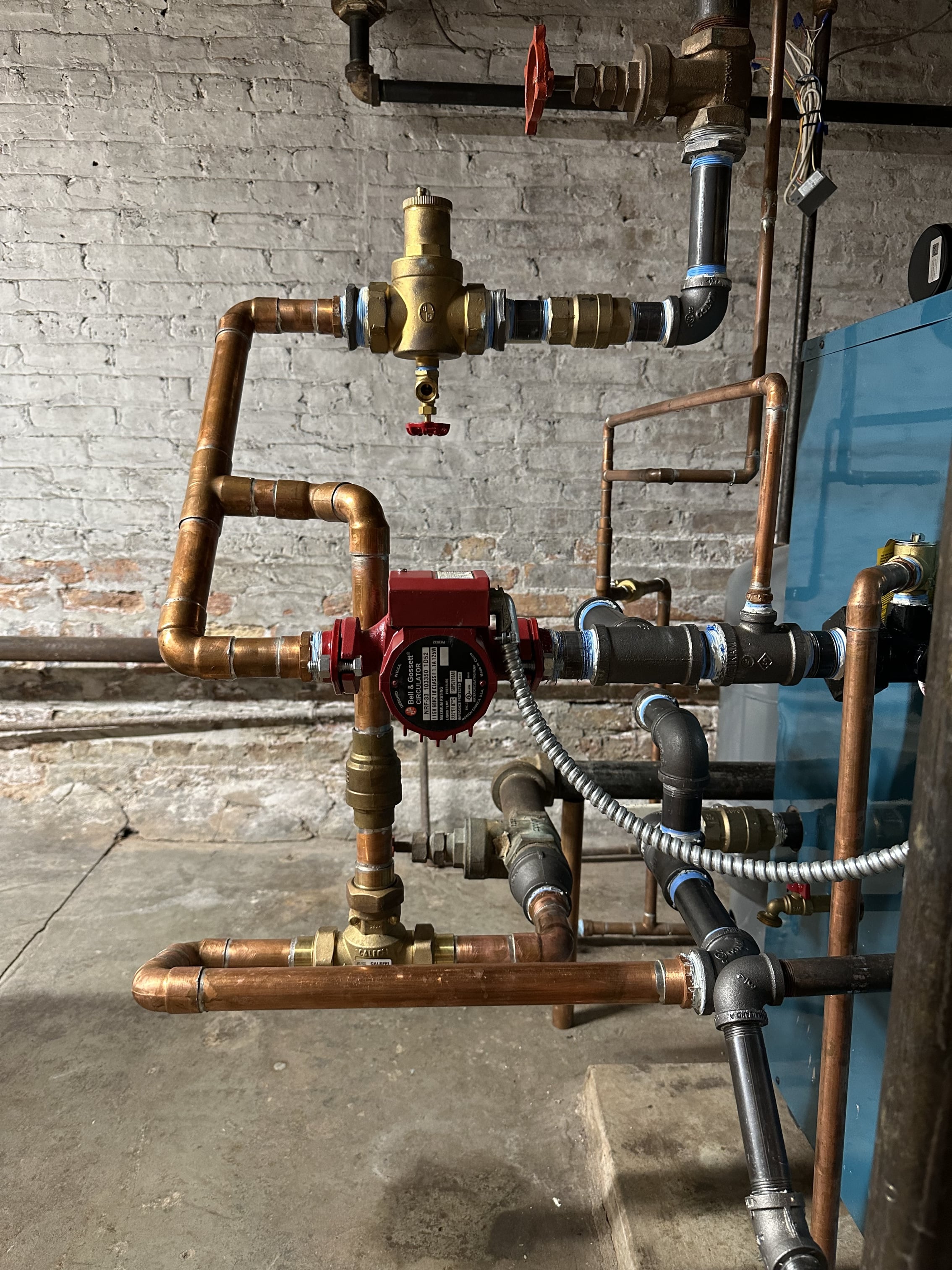
The red thing in the photo is the B&G IAS (Inline Air Separator). It's piped to a compression tank above, and the fill valve connects underneath (not yet connected).
Below is the photo I sent to @OldawgBryant in an IM,
Eric
 1
1 -
I recently had this valve installed on my Burnham X-209 and was curious about @EricPeterson's experiences with balancing issues thereafter.
I had this boiler installed a month ago and noticed it was always operating at fairly low temperatures (the boiler temp on the system board never registered higher than 137, and when I used an IR thermometer on the incoming and outgoing pipes I never saw supply temps above 135F). Return temps were never, and I mean never, above 120. Generally 110-115 at the highest, and I never saw delta T above 15. My system is large (2100 sq ft EDR of cast iron boilers) and is presumably a gravity conversion (the piping near the boiler is enormous, 4-6 inch pipes in some spots). The circulator is an NRF-33. I want to emphasize that his system was completely capable of keeping my house warm at these lower temperatures. All the radiators in my home felt pleasantly warm during calls for heat, etc.
Because I am trying to be an educated user of this system, I read the manual on the boiler and found the section on low return temps, and after searching about this phenomenon (and discovering this great forum!) I asked my installer to add a Caleffi 280 valve. He did this last week, the 140F variant.
Within a couple hours, I realized that I now probably have balancing issues. A few radiators are much warmer than before. Many radiators are now just lukewarm. Some, in key parts of the house that are furthest from the boiler, are basically cold. I have been able to do some rebalancing on 1 or 2 of the hottest radiators, but most radiators in the house have balancing valves that feel completely stuck, so I don't want to risk breaking them during the heating season.
I am curious about what folks in this forum might suggest I do to get back to more balanced heating. I have ordered the 130F cartridge, but I also wonder whether the protection valve has constrained flow enough (at any set point version) that I might need a bigger circulator.
Thanks in advance for any of your suggestions!
0 -
Hi @tcovert83 - good job on identifying this issue and taking action to avoid problems down the line.
To answer your question, I've not had any balancing issues since installing the Caleffi. Initially I was unsure as to whether or not installing it in the manner I did would allow proper flow to the system, but as it turned out I did not not experience any problems. Had there been issues I think the solution would have been to redo the near boiler piping with P/S. I did switch out the circulator (replaced a NRF-22 with a Grundfos Alpha) but that was to reduce the noise when the boiler was cold starting and the water in a tight loop through the valve.
That said, prior to this I spent considerable time and effort in balancing the system:
- split house into three zones:
- Family room / kitchen addition + basement
- First floor of original house
- Second & third floors of original house (plus additions to second and third floors).
- installed TRVs in second floor bedrooms (to avoid oveheating).
- relocated thermostats to coldest room of each zone.
- fine-tuned first floor zone by individually adjusting the radiator valves (regular ones, not TRVs).
- same fine-tuning on second / third floor zone on radiators where I did not install TRVs. These are in bathrooms - my initial thought was no ever complains about a bathroom being too hot!
These efforts were all done before installing the Burnham in 2010, the Caleffi came a few years later.
On a side note, what did your contractor have to say about using the Caleffi? I'm just a guy working on his own house, but using this type of valve seems to me like a no brainer for systems like yours and mine (cast iron boilers and old houses with lots of water and radiators). But maybe there are some flow issues with other systems. My near boiler piping is mostly 1-1/4" with some 3" remnant sections of the original. For zones 2 and 3 I replaced the original 3" supply pipe with two 2" pipes (one for each zone) since the 3.4 in² cross-section of a 2" pipe is about half that of a 3" pipe (7.4 in²).
Will be interested to hear what you figure out with your system. I have been very pleased with the operation of the Caleffi.
—Eric
0 - split house into three zones:
-
There is very little pressure drop through the valve the 1" is a 10 Cv, the 1-1/4 is a 14 Cv.
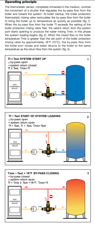
The valve works around a 18° differential. The graphic below helps explain the operatio. at various temperatures.
So with the 140 sensor, the lower right port in these drawings starts to open and allow a % of the system return to blend with the supply from the boiler. The valve is similiar to slipping the clutch in you standard transmission vehicle. It is not an on/ off type valve, it modulated as the temperatures change
With the 140 sensor the return needs to reach 158° before the upper, bypass port closes 100%. So you will not get 100% flow to the system until the return is at 158°.
Actually on my own system I changed to a 115° sensor, part # (F29633) so 115 + 18 = 133° boiler return. That should be adequate to protect gas or oil fired boilers. Thie will get you to full system flow quicker and at lower return tem[erature requirement.
 Bob "hot rod" Rohr
trainer for Caleffi NA
Living the hydronic dream0 -
My contractor had basically never heard of the part, which made me not exactly sure that it was the right call, or that I might need other changes after its installation. This is why I am coming here for your (and @hot_rod's) guidance!
@hot_rod in the first few days of running with the valve I have not yet seen return temperatures high enough for the valve to open all the way. the highest (pre-mix) return temp is barely 130F, as measured by an IR thermometer aimed at some rusty cast iron pipe. is your view that 115F return water is indeed hot enough for my boiler? I have the 1 1/4 version, currently with a 140F cartridge. the reason why I am wondering about circulator flow is that before the valve, I had a delta T of about 15, which suggests I was getting like 30-31 gpm through the system. All the radiators in my home were pleasantly warm in this state of the world. I am now seeing delta T of about 50, so my circulator is presumably delivering 1/3 as much flow as before.
0 -
What size boiler, how many radiators?
What temperature is the boiler set to? Does the boiler ever cycle off?
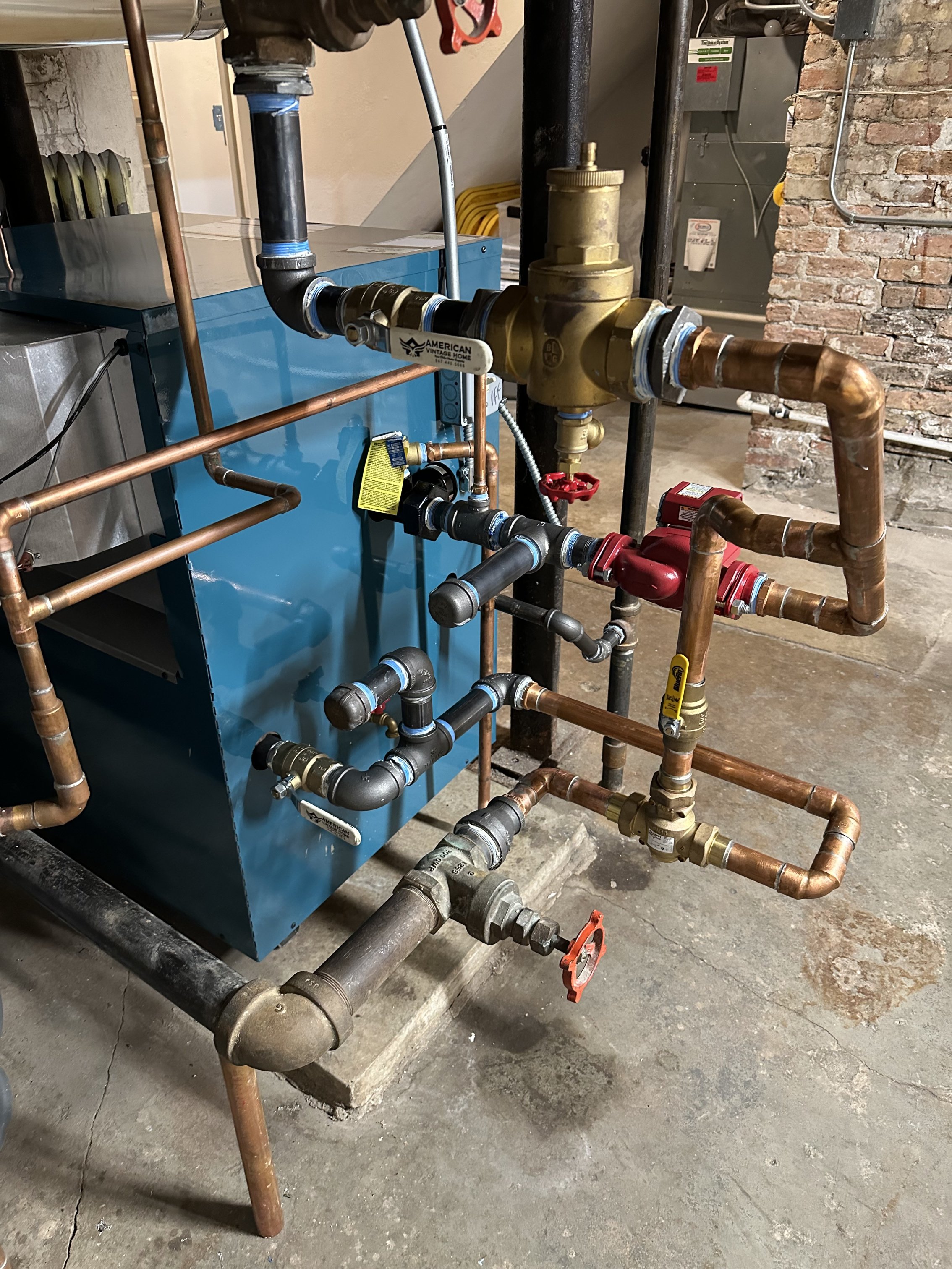
Got a pic of how it is installed?
Bob "hot rod" Rohr
trainer for Caleffi NA
Living the hydronic dream0 -
The boiler is a Burnham X-209 (280,000 btu/hr in, 84% efficient, running nat gas), and the circulator is an NRF-33. There are about 30 cast iron radiators (about 2,100 sq ft of EDR), and I'm my system was originally gravity fed, as the supply and return pipes closest to the boiler are enormous (4 inches? 5 inches? I can't be sure). The boiler's current max temp is 180F, and yes, I do see cycling now that the protection valve is installed. I've attached some pictures.
 0
0 -
working some numbers, you have about 235,000 actual btu to move thru the system. At a 20 delta that would be 23.5 gpm required
23 gpm thru that 14 cv valve is about 6’ head, with piping fittings valves, call it 8’
The pump you have at 8’ head is giving you 8-10 gpm. So 500x 8 gpm x 50 delta = 200,000 btu delivered. with a 50 delta you are moving a lot of btus, so expect a cold return until all that mass warms up
When were the TRVs added? With the 280, piping, valves ,etc you are up near the top of that circ.
The 33 is a high gpm low head circ. With little pressure drop in a gravity system it is a good match. As you add components (pressure drop) your gpm will go downAny idea what the heat load of the home is?
Bob "hot rod" Rohr
trainer for Caleffi NA
Living the hydronic dream0 -
there are no TRVs, just old, mostly seized manual balancing valves.
My installer estimated 200,000 btu/hr heat loss on design day. The boiler was actually installed two days before a pretty sizable cold snap (below design day temps for my area) and the boiler ran about 16 hrs on those days. This was before we had added the protection valve, and the house was plenty warm with ~130F (maybe 140F? Definitely no higher) supply water.
As I said above, we’ve now got plenty of cold radiators (not all, some are now too hot), I’m guessing because our flow is so much lower than before. What do you think I could/should change?
0 -
@hot_rod - I think you picked up the bit about TRVs from a comment by me regarding my system, not from @tcovert83. Perhaps he has them but I don't think he mentioned that in this discussion.
Since I have a Grundfoss I can tell you the circulator is currently pushing 5 ft of head @ 10.5 GPM (zones 1 and 3 calling for heat). ☺️
Eric
0 -
the radiators will always dictate the operating condition of the boiler. If the boiler ran for 16 hours and never got above 140 SWT, without the 280 valve? That would indicate you have more radiator capacity than what the boiler can keep up with. If this was at or near design day condition, it could also indicate the boiler cannot keep up with the load?
Granted during a cold snap all that cast iron and water volume in those gravity pipes will take hours to warm.
Boiler thermal equilibrium will always be reached at some point in those long heat calls.
If you observe the SWT and the RWT, when they stabilize neither going up or down then the system is taking all the boiler can give. If the SWT never rose above 140 SWT during that period, then of course the return will never get above the required temperature for boiler protection.
The 280 Valve cannot change the match up of boiler to radiator, it mainly keeps bypassing a % when SWT and hence RWT is too low.
The lower temperature element will allow a greater portion of SWT to the system and close the bypass 100%, sooner
Hopefully you can get more near design conditions to collect more data.
A good thing is the boiler does cycle off at some point? You will or should see that condition any time you are warmer than design.
Ideally the boiler if sized properly will run non stop on a design day at a safe operating temperature condition.
Bob "hot rod" Rohr
trainer for Caleffi NA
Living the hydronic dream0


Categories
- All Categories
- 87.7K THE MAIN WALL
- 3.3K A-C, Heat Pumps & Refrigeration
- 59 Biomass
- 430 Carbon Monoxide Awareness
- 129 Chimneys & Flues
- 2.2K Domestic Hot Water
- 5.9K Gas Heating
- 122 Geothermal
- 170 Indoor-Air Quality
- 3.8K Oil Heating
- 79 Pipe Deterioration
- 1.1K Plumbing
- 6.6K Radiant Heating
- 396 Solar
- 16K Strictly Steam
- 3.5K Thermostats and Controls
- 56 Water Quality
- 51 Industry Classes
- 51 Job Opportunities
- 17 Recall Announcements