Sanity check on older hydronic boiler setup

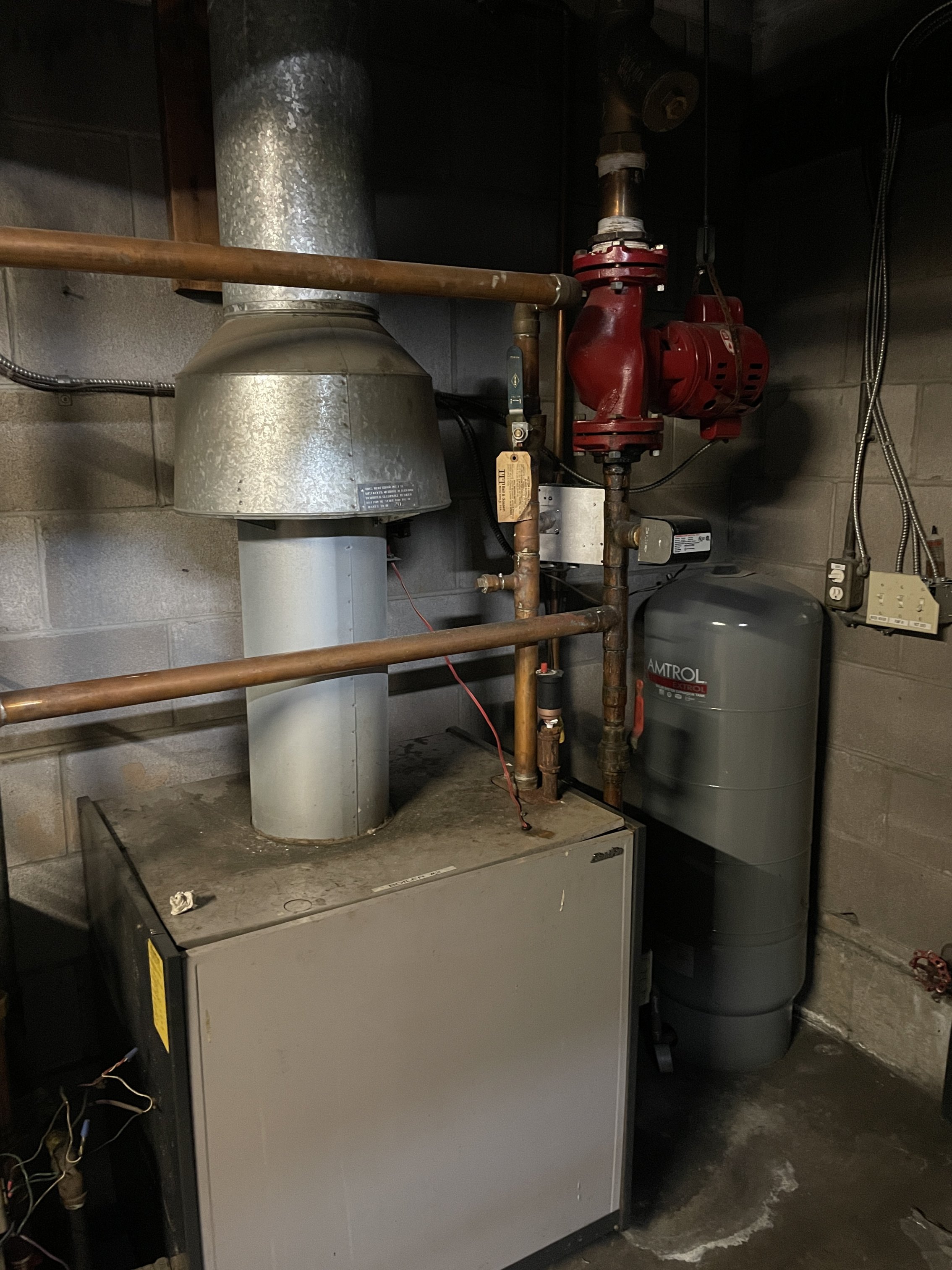
I think the install was somewhere in the early 1990s. There are two slant fin gas fired cast iron boilers each 280k output btu. The system is running at ~27psi on a 28 unit (mostly 1 bedroom) 4 story wood frame building from the late 60s. The controls just seem to be based on hi/low set points of 220/180.
Each unit has 3/4 copper pipe with radiant fin baseboard heaters.
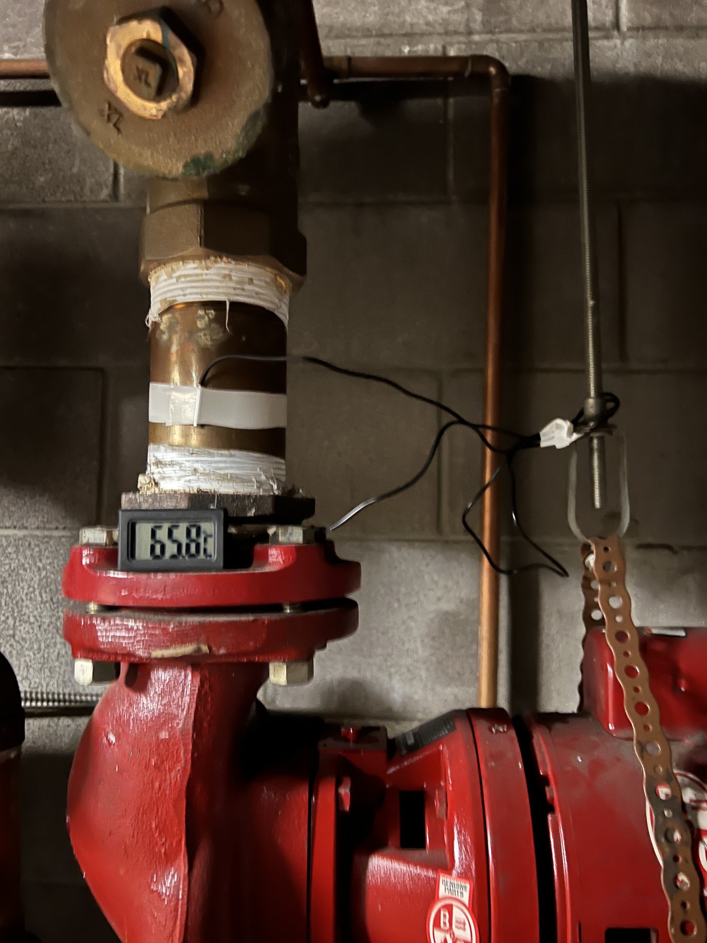
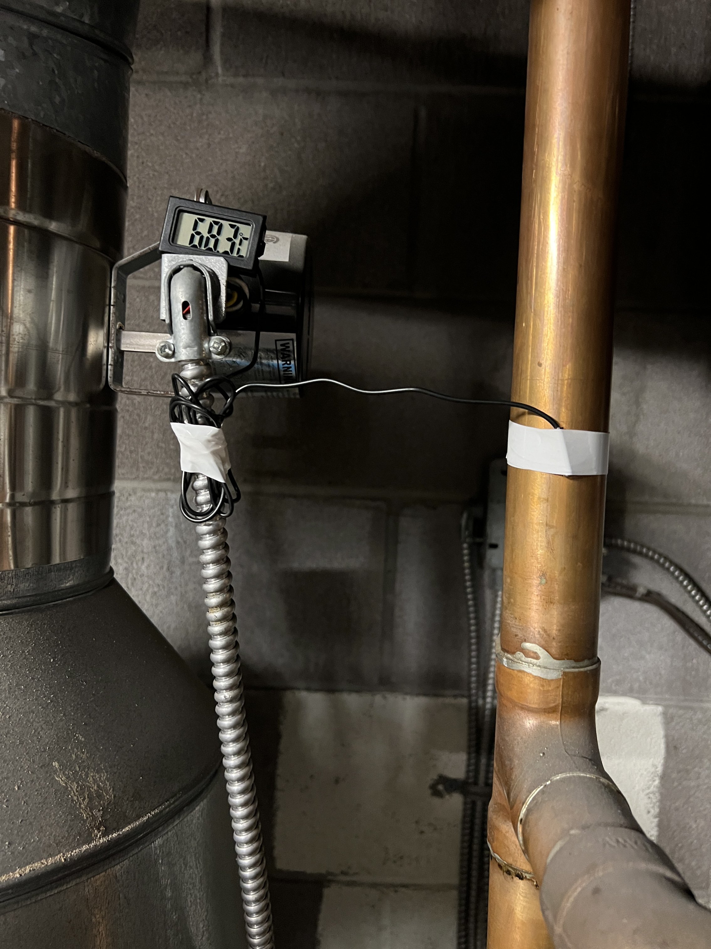
Building seems to run hot. I put some surface mount temperature probes on the return pipe to the boilers and the output pipe from the boilers. The output shows as 155F ( 68.3C ) and the return shows as 150F ( 65.8C ) giving a delta T of 5F which doesn't seem good. Also note that since these are surface mount probes I'd guess the water temp to be at least 18F higher than measured.
I am thinking a better boiler controller maybe a tekmar would be the ideal option to get closer to a 15F delta T. In the meantime should I adjust the set points for the boilers such that the water can get colder before the boilers are firing up and is only heated to a lower temperature before being distributed to the hydronic supply piping? Maybe 200/160?
Comments
-
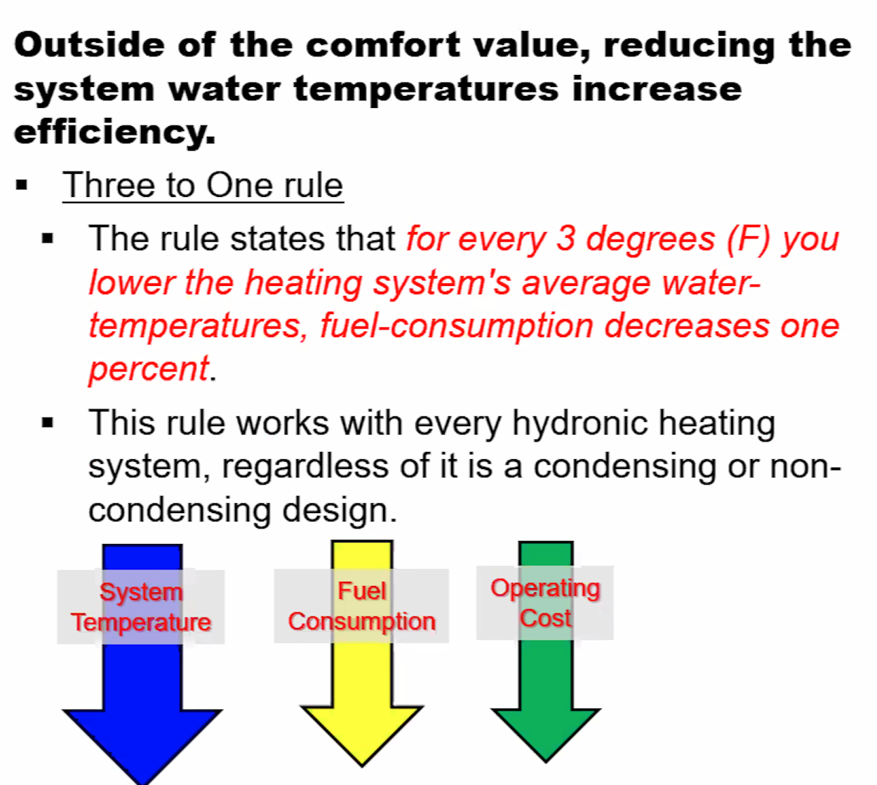
180 is usually the design setpoint in small modern systems.
is that a 50psig boiler? your pressure is high for a 30psig boiler but the height of the building might need something close to that pressure. some math shows that even if the highest emitter is 40 ft above the boiler you only need a little over 20 psig to reliably fill the highest emitter.
1 -
you need to get better temperature collection if you measure 150 but think it is 180?
The surface probes work well if tightly fastened and covered with a piece of pipe insulation or foam.
When the delta is measured is important, are both boilers running, how many zones are calling?
Any idea of the heat load of the building?
Ideally the system needs to run for a period of time to allow temperatures to stabilize to get system delta accuracy
Bob "hot rod" Rohr
trainer for Caleffi NA
Living the hydronic dream1 -
That delta T…if it's really only 5 degrees on a 280,000 BTU output boiler, it implies a flow rate of over 100 gpm… ???
You can get very accurate temperature readings by wrapping black electrical tape around the pipes and shooting the tape with a $15 IR thermometer. I've checked that method against a $300 thermal imager, and the $15 IR thermometer is within 1%.
 1
1 -
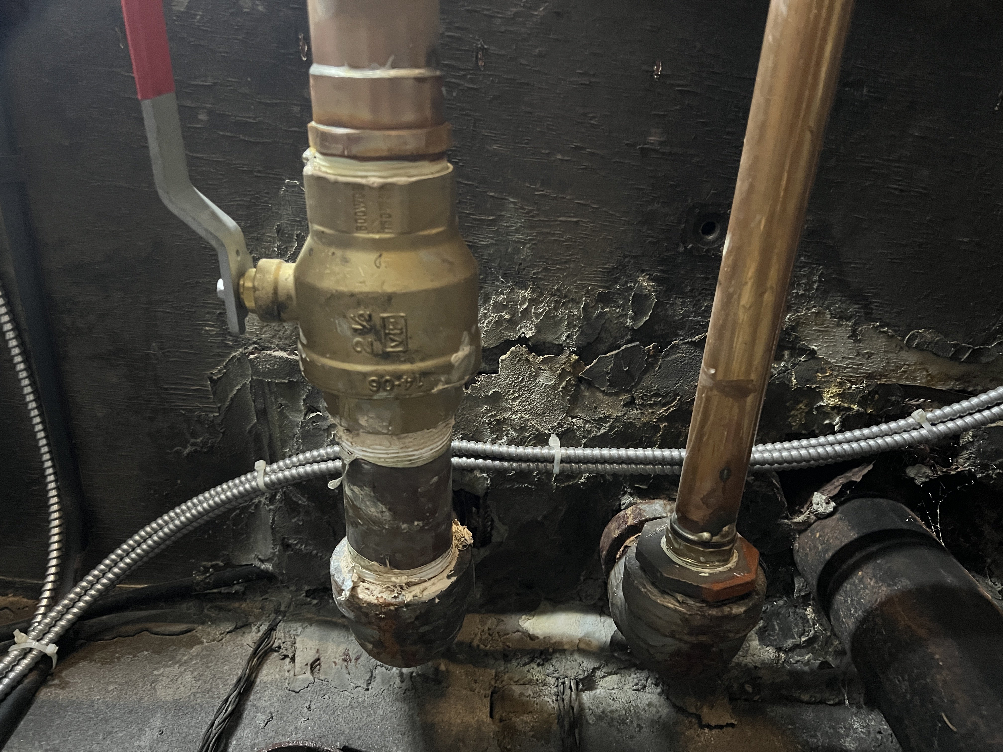
They are 30psig boilers. I could try lowering the pressure. The pipes are black iron for the most part from the 60s. Leaks have happened and portions replaced. No dirt mags on the system.
0 -
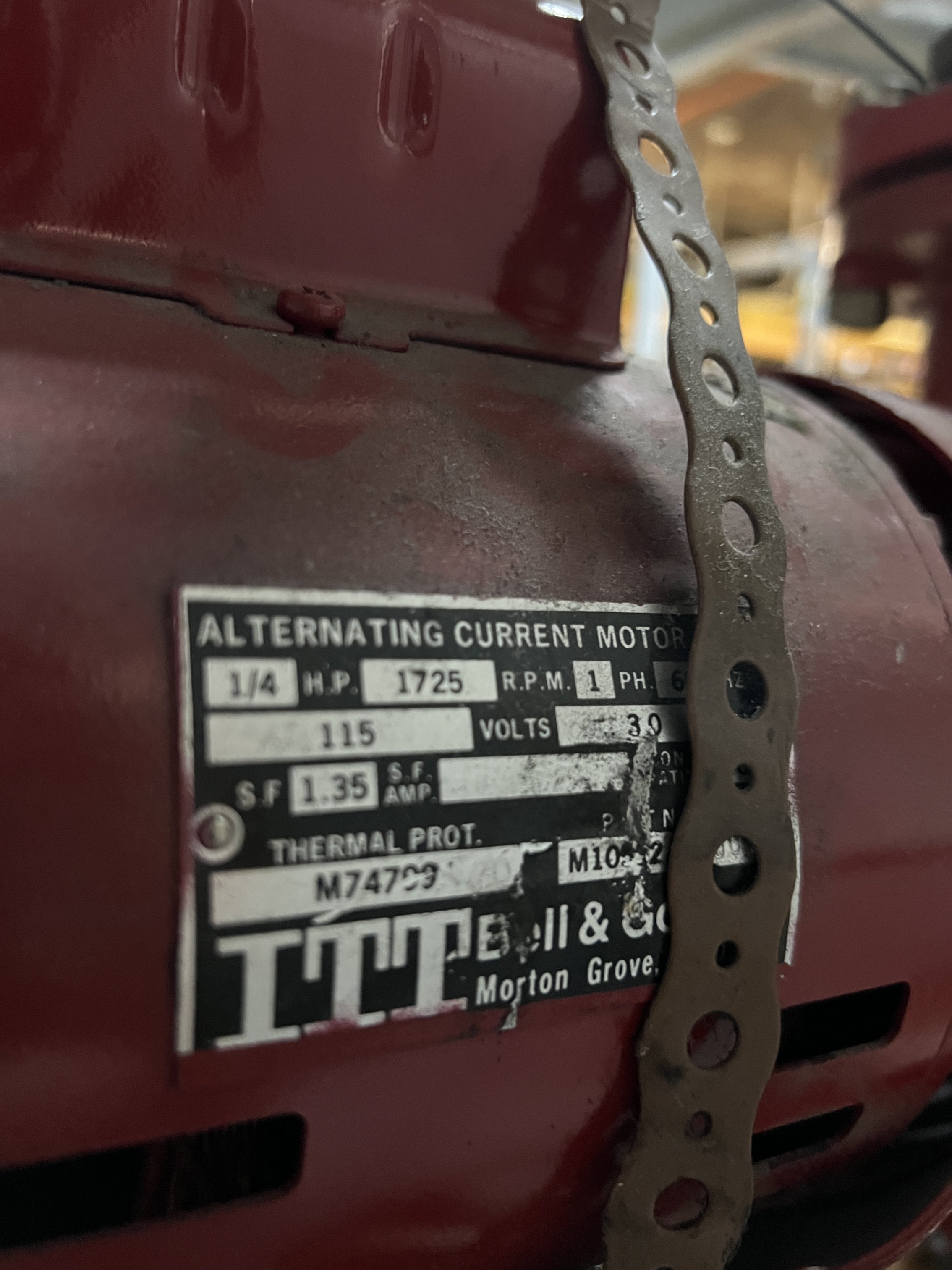
The pump is pretty massive on the 2" return line. 1/4 HP, 1725 RPM, AC. Not sure on what the flow would be.
I think the reading is accurate for the exterior surface temperature of the pipe. If you were to put a temp probe that is in the middle of the water flow from the boiler that is heating to 220 I'd expect a reading closer to 220F.
I have one of these surface temp probes on the output of the domestic transfer tank and it reads 57.5C while the temp probe that is in the water column reads 65C.
 0
0 -
I'll have a better look at the delta T conditions when I measure it. They were both running some of the time but also when just one was running. I tried to wait for the boiler to have been running for a while so I can see the max temperature of the boiler output and I suppose also the maximum coming back into the return.
Since there is only 1 zone in the system, there was one zone calling for heat. There are 22 thermostats but I am pretty sure they all just come down and pig tail into one give me heat call. I'll take a closer look when I am out there next.
Thank you for thoughts on areas to investigate !
0 -
On a 280,000 BTU/hr output boiler running a delta T of 5 F, that implies a flow rate of 112 gpm. In a 2-inch pipe, that's a flow speed of about 10 feet/sec. I'm not a pro, but a pro might say that's too high as above 6 ft/sec can erode copper.
So the low delta T and the high flow rate suggest you probably have a bigger pump than you need. Maybe not worth worrying about. On our smaller boilers we also had higher flow rates than necessary, so I reduced our flow rates by putting triac-based speed controls on the Taco 007 circulators. That slowed our flow rates from 17 gpm to 10 gpm, and raised delta T from 12 to 20.
The triac controls work on permanent split capacitor (PSC) motors. Don't know if that's what you have on those pumps.
1 -
If there are 22 thermostats in an apartment building from the 1960s with hot water baseboard heat, there are probably 22 zone valves in the units. I would look there for the cause of overheating and worry less about the Delta T. The system might be over pumped, but that could be to compensate for balance problems— although they are not likely if it's reverse return.
A good outdoor reset controller could be helpful and save fuel, but that would probably require a large and expensive mixing valve due to the need for boiler protection from low return water temperatures.
—
Bburd1 -
if only a small zone is calling and you have a 280k boiler I would expect some short cycling and fast temperature rise
I don’t know that 1/4 hp circ is moving 100 gpm, 25- 28 gpm flow through a 280k boiler would be typical
There may be a pressure activated bypass on a 22 zone loop
Bob "hot rod" Rohr
trainer for Caleffi NA
Living the hydronic dream1 -
Depending on how the system is set up, you might get a double benefit from @RayWohlfarth 's tip on pg 20 of his book "Lessons Learned Troubleshooting Hydronic Heat." He says he likes installing a time delay relay on the burner. On a call for heat from the thermostat(s), the circulator and time delay relay (TDR) are energized. The circulator starts immediately, and if there's any residual heat in the water, it provides heat to the radiators for the 10-15 minutes of the time delay. Then after 10-15 minutes (or however you set the delay), the burner is energized.
Ray says that in most instances, the call for heat ends without the burner starting. Obviously this only works if the boiler isn't typically cold-starting, which it sounds like it isn't. With 22 different thermostats, it sounds like the boiler is running often, with the resulting high water temps. If so, adding the burner delay should reduce average water temps and should also improve efficiency.
1 -
so do we have any idea how it is piped to the apartments. are they 3/4" parallels off a 2" main. of course the ideal would be to get a zone valve in the line for each apartment but lot of work unless the building and chases were designed with accews to the takeoffs. if you did get control on a zone valve basis then you would want a variable speed pump with a pressure delta response. maybe a controller for the pump you have or compare the payback for a fancy **** wet rotor.
although i used a pair of smaller single speed wet rotor to replace a massive 1 HP dry rotor pump from the early 70s – it was a couple taco 011s iirc. they were in a modestly similar situation for 10 units that uses fan coils all parallel that used to have zone valves that have all given up and of course the thing wasn't made with any kind of modular rational way to replace 'em. removed all the zone valves and used a tekmar ODR, well a TACO PC702 which is a relabeled tekmar, that would handle your boiler staging and the system balances pretty well and the tenants can turn the fans on or up in the fan coils to compensate for comfort. you don't have the fans although depending on the extent of element and house furnishings you could have folks who are getting overheated on a relative basis swing some of the baseboard covers closed.
are the boilers primary secondary with their own pumps or serial or ?
I gotta tell you in figuring out the apartment balance with a single circ for the whole deal i'm real happy with the wifi thermostats so I can monitor the apartments simultaneously depending if you got signal in the building you can use although they usually require 3-wire setup so it depends what was originally installed.
the system i describe i ran 24/7 like a radiant floor. you'd still want some kind of averaging thermostat since you can't take your return too low with those boilers so you probably be fine on offing in 2 -stage fashion although in the NFN department we've been running through two staging atmospheric boilers on the steam side. if you're short cycling in shoulder season you could use two stage gas valves to go effectively make it a 4 stage setup.1 -
Reading through this more I miswrote. There are zone valves in each unit so I guess that does make 22 zones. I believe each zone valve is on the return side of the typically 2 baseboard heaters. The 2" main supply does branch down to 3/4 or 1" lines that then feed a vertical stack of units ( typically 2-3 units in a stack ). I'll have to take another look over the system as it seemed to me that the supply side was smaller than the return side but there is a lot to look at and when everything isn't super familiar it is hard not to get lost in the details. WIth the 22 zones I do expect that at least one zone is always going to be calling for heat.
I'll have a few reads through your response and seem if I can absorb it. I like the idea of the wifi thermostat which could allow me to see what temperature each unit is experiencing. Not sure if there is an off the shelf solution that isn't 22 tabs in a browser. I think the wiring to each unit is just cloth 18/2 thermostat wiring with 24vac transformers in the boiler room not sure if it would be possible to use the existing wire as a pull or if low volt wires were typically secured to framing in the 60s.
Thanks for the ideas.
0 -
There is only the one pump. The boilers appear to be serial with the thermostats/zv.safeties and the hi/low set points to control firing.
0 -
Ultimately it comes down to simple math. Heat loss of the building on a design day must be equal to the output of all the radiators at a given supply water temp. You should be able to gradually dial down the hi limit until you find that balance point. Then maybe go back up 10 degrees or so for margin.
In our 100-year-old 4-unit building in Boston area with a massive amount of cast iron radiation, we could heat the building on design day with 120-degree water. But obviously with baseboard radiation, you'll need higher water temps.
1 -
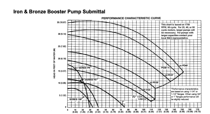
Two pumps on this chart are the 1/4 hp model, either the 2-1/2 or the HD 3 theses are considered flat curve circulators ideal for zone valve systems.
Ideally a circ runs mid curve so you would be pumping 40- 60 gpm range. Those two boiler at 80% is 448,000 btu/hr available. So that 40- 50 gpm range seems about correct.
448,000÷ 22 units= 20,000 btu per unit heat. That would be about 40' of fin tube per unit??
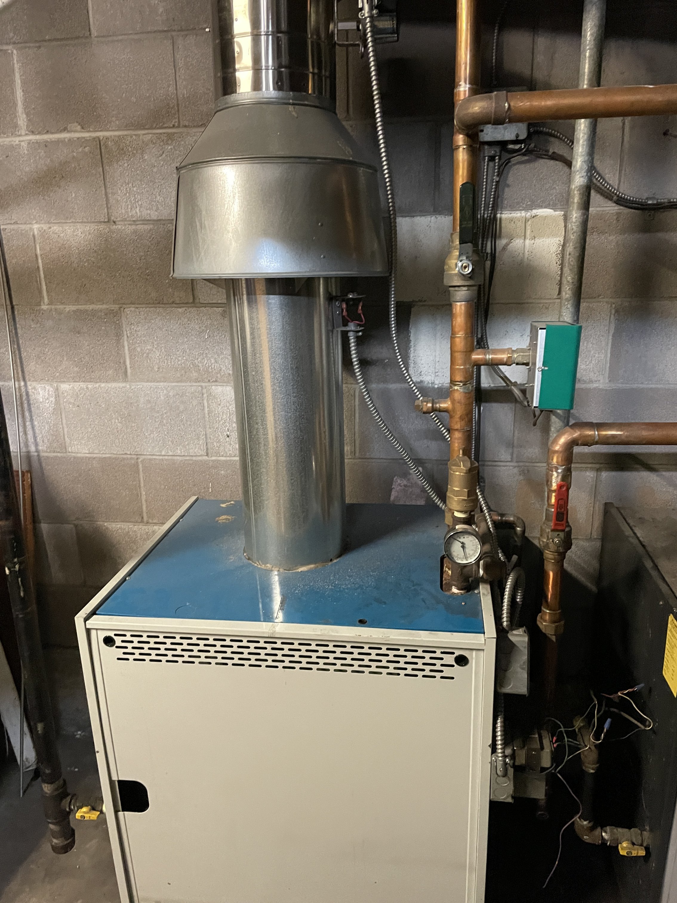
A picture of the near boiler piping would show how the system is piped, where flow goes as zones close off.
If you are looking to make the system more efficient I agree the ODR control could maybe run the boiler at lower temperature for some, maybe much of the season.
An ECM type circulator would cut pumping costs by 50% or more.
There are many incentives available for converting to ECM circulators, and probably programs to have energy upgrades done. Find your state here.
www.dsireusa.org

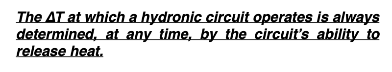
Don't get too hung up on delta T, it will be constantly moving in hydronic systems as the loads are constantly changing. This is an important condition to know. With 22 units that delta will vary quite a bit. The heat emitters driver the operating condition of the boiler, temperatures and ∆s
 Bob "hot rod" Rohr
trainer for Caleffi NA
Living the hydronic dream1 -
I'll measure the length of the baseboard heaters. I think there are 3 x 10' for a unit.
I posted the output btu of the boilers so I think that already has the 80% cooked in.
I'll grab some pictures of the piping to get a better sense of how it is piped.
Had the wrong number of units. There are 29.
It makes sense that the delta T isn't going to be super helpful with 28 units and is going to very based on season.
ODR control and variable pumps are likely to be the easiest upgrade path. I'll mess with a lower set point. Fairly close to design temperature days atm. Do buffer tanks ever make sense to keep the boilers from short cycling? I'll watch the system for a bit and see if I can get a sense of the cycle time for each boiler. The boilers are in parallel - now that I look at the pictures closer.
Thanks for all the information !
 0
0 -
-
29 small zones on a` single output boiler will be a challange. The smaller the load, the shorter the load duration, the more cycling you can expect.
The rule of thumb is the boiler runs for about 10 minutes when it fires. That generally warms the boiler, flue piping and return temperature above 130°F
ODR on a cast boiler will have some limitations, you may not go much below 155- 160 or so to assure the return temperature rises above 130F.
You might just crank down the current control to 170, 165 see how often the phone rings :)
Bob "hot rod" Rohr
trainer for Caleffi NA
Living the hydronic dream1 -
staging the boilers would make a whole lot of sense. It sounds like the boilers are a bit oversized.
if you do odr you need to either limit it such that it doesn't fall enough that the return water temp doesn't fall below 130-140 or add return water protection to the boilers.
1 -
PS @hot_rod as long as no snowmaggedon again this weekend maybe you can splain the pressure activated bypass for me or point one out in vegas. never seen one. used to have an early ODR style electric proportional bypass valve but with a bulb outdoor sensor on the system i mentioned above when i ninherited it with a million btu oil burner. that boiler was installed in 1969. i did take the DHW off it but the i'm doing it with two 140M munchkins and direct temp ODR these daze.
0 -
thats some pretty crazy near boiler piping. best i can tell the boilers are parallel on 1" for the near boiler except a 1 and 1/4 cross on the feed to the left hand boiler. i assume out of the picture on left hand boiler the pipe increase to 2" so this constriction is for short run but you'd have to have some serious velocity in that near boiler piping to handle 80% of the nameplate on those 2 boilers.
can't see where the PRV and expansion are connected so hard to tell if it is pumping away and that might also explain high operating pressure. with 4 stories I would always operate mine up in the mid 20s although i had the pumps on the feed so it actually would show 30 leaving the pumps for the system but would return with pipe loss around 25. so i had to charge the expansion tank up to accomodate and because it was constant on i didn't blow off the relief virtually ever even though i was theorectically close.
on the one hand parallel circ is going to cut down cold starts when calling the second boiler but usually i might see something like this as primary secondary. and you could cut down on your system pump while you would have to add boiler pumps. with modern pumps you'd spend some money but save electric.. doubt it would payback in electricity but if it contributed to better control and comfort for less energy could be worthwhile.
in a way though, those pictures demonstrate how almost anything will work cause it seems like its been that way for some time and aside from the balancing problem it works. still don't see any pictures and don't know if you have any access to see how this main manifolds to the individual units or if this 2 inch main disappears and returns but these unit connects are all hidden (and presumably not active by way of zone valves, nevermind say manual isolation valves if you had to work on one unit).
i doubt you're going into the unit by unit heat exchangers but if you want to use ODR with baseboard, you can't have enough fin. where I can i used the higher 'commercial' baseboard and put two runs of fin tube in it. but much of our hydronic insyallked base goes back to the days when they designed for 180 degree water to heat the place so they didn't even always put one full run of fin in each enclosure. when i started it was only my economic instinct that stopped me from doing that. it was almost the same price to buy enclosure and pipe as to buy enclosure and fin tube so i reckoned if a room was too warm they could just close the vents on some of the enclosure. in the end those places with lots of fin have proven much more resilient to ODR approach although the drop off in output is geometric not arithmetic. between that and having to guard return temps (something you could modestly ameliorate with a close loop primary secondary or storage tank) you don't get as much flexibility.
but not inconceivable if you are short cycling in shoulder season even with only a single boiler running to two stage those boilers.1 -
going back i just saw the post that there are zone valves. if that is the case variable circulator and two staging the boilers might be really good go. unless some of the zone valves aren't closing it seems odd that you get a lot of heat overrun in some apartments since there isn't a lot of mass in the baseboard.
if you got hot apartments i'd check zone valve operation.1 -
Ok so a little more looking at the system.
Boiler controls are set to 180/160.
System pressure is 27psi, the expansion tank measured to 10psi (with shutoff enabled). Tried a bicycle pump to increase pressure but wasn't effective do you generally need to use a compressor for larger expansion tanks like this?
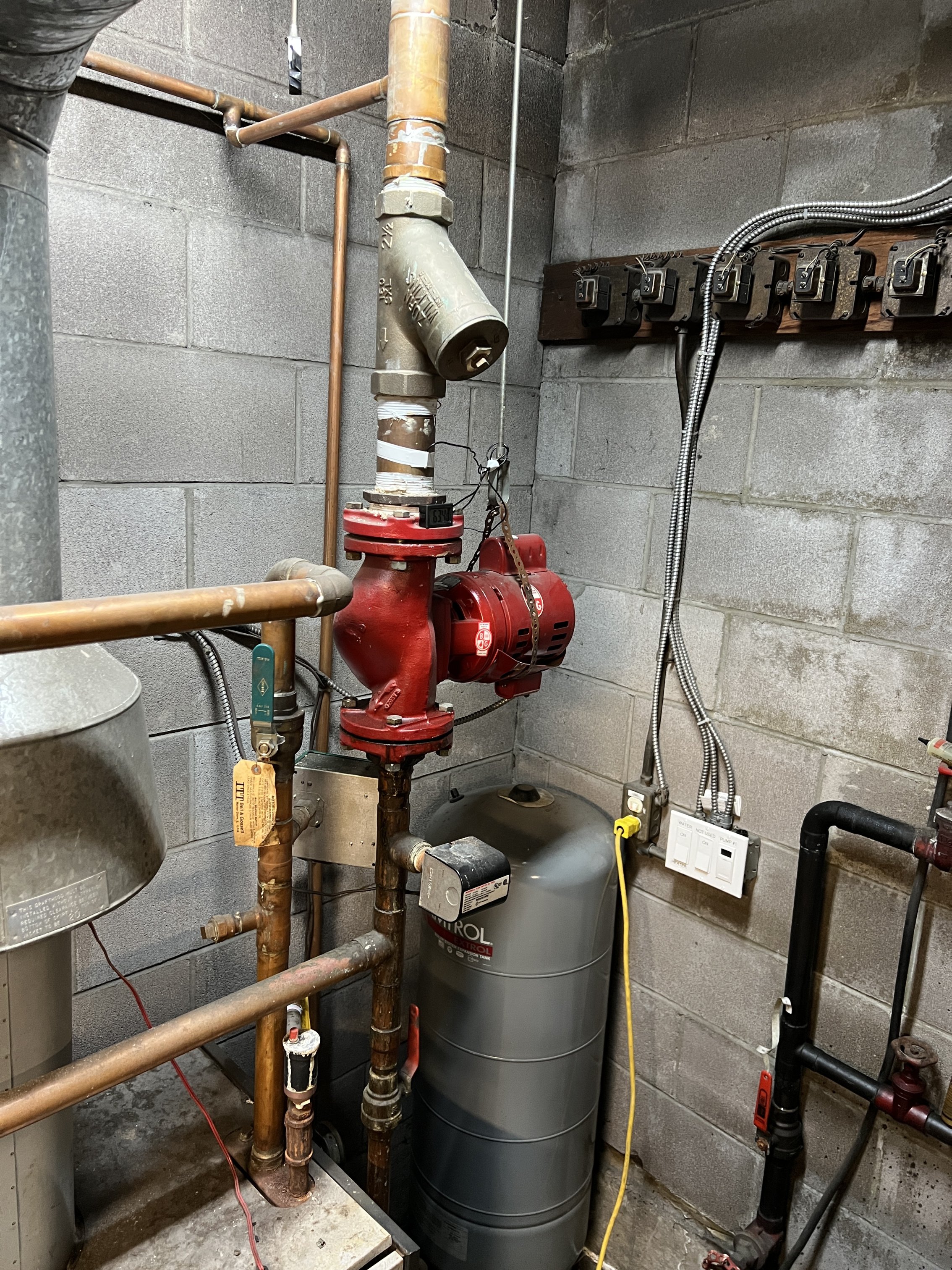
The pump is pump away from the expansion tank but the expansion tank is connected via 1/2" or maybe 3/4" pipe from the 2.5" line.
The return pipe is 2.5". The output pipe from each boiler is 1.25 but that doesn't enlarge until it hits the main pipe that is going to distribute to the building. I assume there is a perpendicular trunk that then branches to 3/4 lines that then feed vertical stacks of units. Assuming each 1 bedroom unit has 20' of baseboard would a 3/4 line be enough to feed 3 units? Possible there are only 2 units stacked.
Thanks again for all thoughts !
 0
0 -
It looks to me like the expansion tank is piped into the 2.5" return above the pump, and the pump is pumping the 2.5" return down into both boilers. That is "pumping away" from the tank as you say, but it's pumping "towards" the boiler. That means that the pump is adding 17 psi to the 10 psi static pressure in the tank to get 27 psi in the boiler. So don't add any pressure to the tank, because whatever pressure you add there will reduce your already slim 3 psi margin on blowing the 30 psi relief valve.
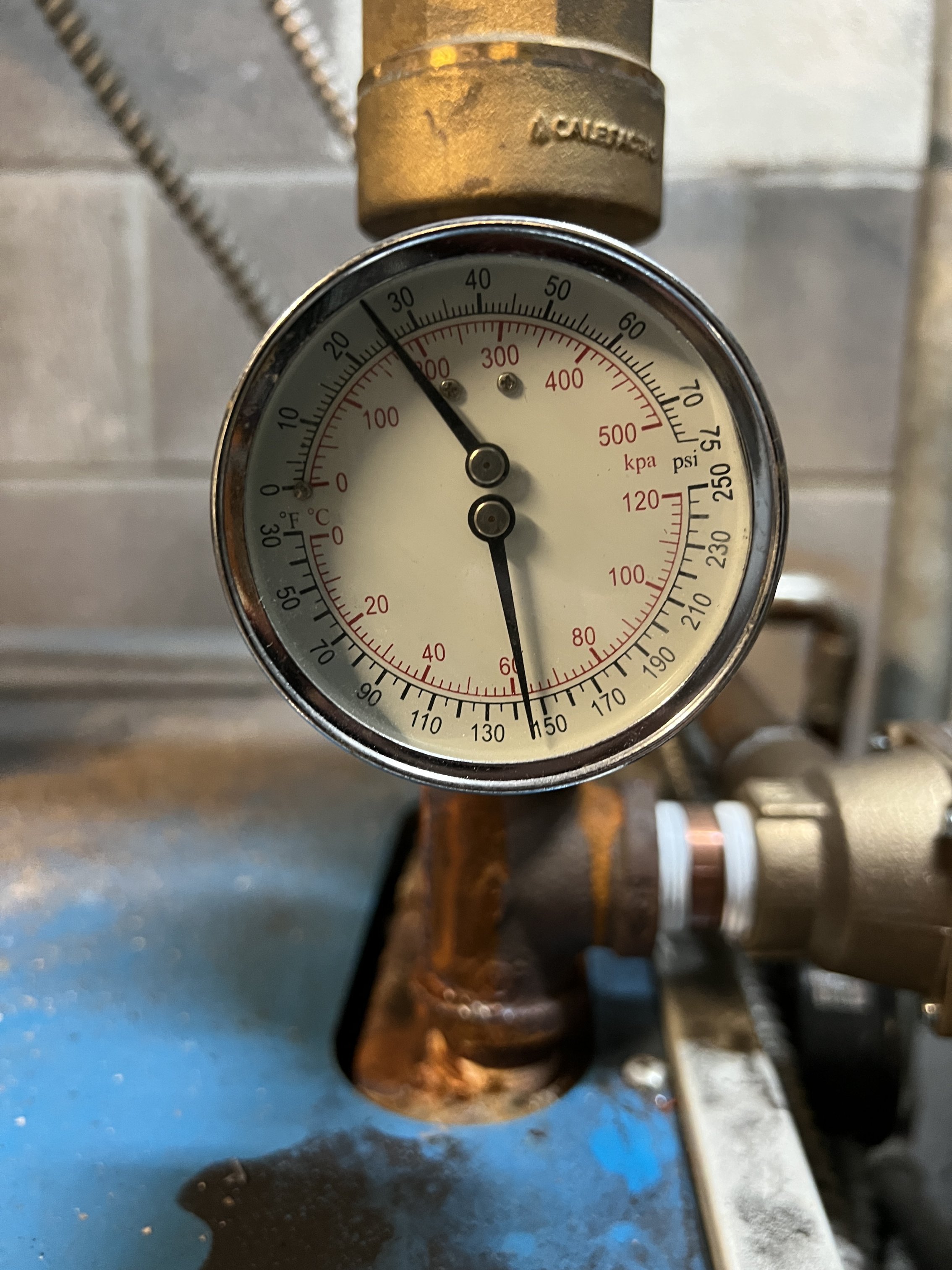
Also, beware that those boiler pressure gauges can be off by 5 psi or more. So you could be even closer to the 30 psi relief valve setting than you think…or farther. Best to put a known good pressure gauge on a drain fitting somewhere if possible to get an accurate reading.
As for the 3/4" pipes, at max recommended GPM and 20 degree delta T, a 3/4" pipe will deliver 40,000 BTU/hr. So 20,000 BTU/hr for two units, or 13,000 BTU/hr for three units. You say each unit has 20 feet of baseboard, which is good for about 11,000 BTU/hr. So the 3/4" pipe should be OK. Proof of the pudding is if the units are warm enough in winter. If no one is complaining, the pipe sizes are OK.
1 -
Thank you. Just curious about the 17psi added by the pump. How do you know it is 17? Did you just take the 10psi off what the boiler gauge is reporting? If I turn off the pump, should I expect the pressure to drop to 10psi and match the expansion tank?
0 -
Yes, if you turn off the pump, you should have the same pressure in the boiler as in the expansion tank. If there's a difference in readings, it's probably because the gauge on the boiler isn't accurate, which is common. I just checked my sister's boiler gauge pressure, then took an air pressure reading on the expansion tank. The boiler gauge was off by 5 psi (high). And on our two WGO-5's, one gauge is off by about 5 psi.
But in your case, something isn't adding up. You say the air pressure in the tank is 10 psi, and that there's 27 psi in the boiler when the pump is running, which implies the pump is adding 17 psi. But your pump appears to be a B&G HV 2-1/2, which according to the pump curves posted above can only add a maximum of 16 feet of head, or about 7 psi, and that's at zero flow. At reasonable flow rates, the pump's added pressure will be lower. So something isn't adding up. Either your boiler pressure gauge is off by more than 10 psi, or something else is going on.
Are you sure you're reading 27 psi and not 27 feet of head? Some gauges show both units. If it's 27 feet of head, that would make more sense, because that equals about 12 psi, which would be more consistent with the 10 psi in your tank.
1 -
Seems like psi? This pic reads closer to 25. I'll check the pressure in the tank again and I'll bring out my hose bib pressure tester.
 0
0 -
Yes, that's 26 psi. Is that with the pump running? The pump is pumping away from the expansion tank down into the boilers, so the pump head is being added to the static pressure supplied by the air in the tank. If the pump is a Bell & Gossett 1/4 hp 2.5 pump, it can only add 6 psi max (at zero flow rate, which is not what you have), or more likely around 3 psi at reasonable flow rates. So if your 10 psi in the tank is accurate, even with the pump running you wouldn't have more than 16 psi in the boilers, and probably more like 13 psi.
Before you break out the hose bib tester, check the pressure gauge on the other boiler. It's facing the expansion tank. If it's also reading 26-ish, I'd believe the gauges. Then the question is why your expansion tank only reads 10 psi. Are you sure your air pressure gauge is accurate?
Don't put a hose bib tester on a valve that you haven't opened recently (like a boiler drain valve). A boiler drain valve may leak after closing, and then you'd need to put a cap on it to stop the leak.
1 -
Both gauges were reading around 26/27 psi. The pump was on - I am not sure it ever turns off at least in heating season.
The 10psi was with the water shutoff and drained at the expansion tank. The plumber tested it and tried to add more pressure with a bicycle pump which wasn't effective. He has since revisited and increased the pressure using a compressor to 27 in the expansion tank. Prior to testing the expansion tank he replaced the relief valve on the boiler nearest the expansion tank as it was dripping. The replacement also ended up doing the same thing - I worry that the plumber just doesn't have the hydronic expertise. Since increasing the pressure in the expansion tank the relief valve appears to be dripping less. Only the boiler closest to the expansion tank had the relief valve periodically triggering.
I'll check his work on the expansion tank and see what it reads.
There is already a cap on the boiler drain valves so I do expect a leak there.
0 -
OK, things are making more sense now. I assume you're operating at 26/27 psi because you have a tall building (4 stories) and you're trying to keep the static pressure at the topmost radiator at +5 psi or so minimum. All good so far.
The problem with that is, as you've found, you're very close to the 30 psi relief valve setting, and any minor pressure variation can/will make that valve leak. So you either have to be sure to follow the correct procedure when pressurizing the tank (which leaves you the most margin against the relief valve popping), or back off slightly to give yourself more margin.
So the expansion tank had 10 psi air when drained of water. So far, OK. But then tank has to be pressurized with air to the desired pressure (say 26 psi) WHEN STILL EMPTY. If the plumber couldn't get enough air into it, then opened the water fill valve to partially fill the tank with water, then tried to add more air to reach 26 psi, now there's less free volume in the tank at 26 psi, so that when the water heats up further, it will increase the pressure faster and get closer to popping the relief valve.
To put it a different way, you're trying to maximize the empty volume of the expansion tank by setting the system pressure to the desired setpoint with the tank totally empty of water. In doing so, when the water heats up, it has the full empty volume of the tank to expand into, which minimizes the pressure increase as it expands, leaving you margin on the 30 psi relief valve.
Done incorrectly (partially pressurizing the tank with air, then allowing some water in, then adding more air pressure to the tank) means there's now less free volume in the tank for the heated water to expand into, causing more of a pressure increase that gets you closer to 30 psi, resulting in the occasional overpressures that you've seen.
 2
2


Categories
- All Categories
- 87.6K THE MAIN WALL
- 3.3K A-C, Heat Pumps & Refrigeration
- 59 Biomass
- 429 Carbon Monoxide Awareness
- 124 Chimneys & Flues
- 2.2K Domestic Hot Water
- 5.9K Gas Heating
- 119 Geothermal
- 168 Indoor-Air Quality
- 3.8K Oil Heating
- 78 Pipe Deterioration
- 1K Plumbing
- 6.6K Radiant Heating
- 394 Solar
- 16K Strictly Steam
- 3.5K Thermostats and Controls
- 56 Water Quality
- 51 Industry Classes
- 50 Job Opportunities
- 18 Recall Announcements