How Do I Connect This Wire?
Comments
-
Yeah, I think it is a good idea as well.
Chapter 1. How to get a common wire to a Nest
Chapter 2. Taco Switching relay wiring
Chapter 3. How to flare oil line tubing
Chapter 4. All about TIGER LOOPS
@Larry Weingarten has a few books I am sure he could help you avoid some pitfalls

 2
2 -
Hi @EdTheHeaterMan, @EBEBRATT-Ed is right. I'm working on my third book now, so can certainly show you where some of the book biz ropes are. There are a number of authors who frequent this place. Mix up technical, stories, and humor, and you'll have yourself that bestseller. It will be another reason to have spent so much time and effort to learn this stuff. 😻
Yours, Larry
0 -
@Larry Weingarten… I started to do just that. I am going to use the title you suggested. "Keeping the Smoke In".
Edward Young Retired
After you make that expensive repair and you still have the same problem, What will you check next?

 3
3 -
@EdTheHeaterMan , Wonderful! It might need a clarifying subtitle. Otherwise Bill Clinton, and "not inhaling" come to mind. 🤪
Yours, Larry
3 -
It is sure to be a NYT best seller!!!!
1 -
This is a problem with many gas steam boilers when you want to add a smart thermostat that requires a C wire Connection. Here is another Boiler made by Dunkirk that should use an isolation relay.

I find that the Packard FC90113 is one of the least expensive combination transformer/relays available and is very easy to use for the isolation relay.
Edward Young Retired
After you make that expensive repair and you still have the same problem, What will you check next?
0 -
@EdTheHeaterMan , following the link and enlarging the third pic, we can see that unit is made in China. So it won't be inexpensive for long………………
All Steamed Up, Inc.
Towson, MD, USA
Steam, Vapor & Hot-Water Heating Specialists
Oil & Gas Burner Service
Consulting0 -
I noticed on the link that the Packard and the White Rogers look identical with the WR about $2 more. Both made in China.
The Honeywell is almost double the price……….country of origin…….CHINA
0 -
So none of them will stay at that price for long.
All Steamed Up, Inc.
Towson, MD, USA
Steam, Vapor & Hot-Water Heating Specialists
Oil & Gas Burner Service
Consulting0 -
@Steamhead & @EBEBRATT-Ed… You can purchase a "Fan Center" from a boiler manufacturer for over $100.00 and find that it is identical to any of the lower priced items. The "rub" is that the wire colors are different. Since many plumbers (and even some electricians) are not that good at control wiring, changing the colors of the wires make it difficult for some to adapt the identical low cost part with the expensive "Factory Authorized" part.
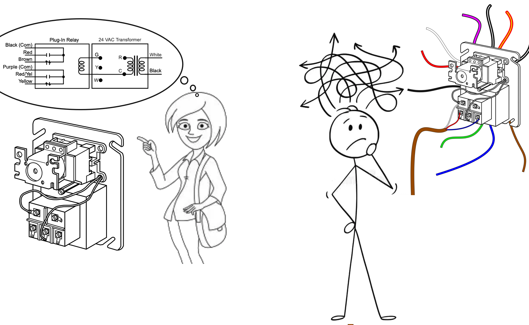
Regardless of the political climate. The boiler manufacturers will always have an excessive markup for the generic parts they sell. That is why they have slight changes in them. Just so you won't try to buy the lower cost generic parts. That is the reason I like Crown by Velocity Boiler Works over Weil McLain. Crown will tend to use standard parts for their boilers rather than modified "OEM" parts.
When the Tariff's kick in, you can see the OEM fan centers go from 100 to 200 while the generic will still cost less than 50.
Edward Young Retired
After you make that expensive repair and you still have the same problem, What will you check next?
2 -
If they go up that much a transformer and a RIB will work and nut much more work to install.
Wasn't there another relay like a RIB that had a transformer built into it? Someone posted it last year I think. But maybe the trans is to small for a Nest.
1 -
I think that RIB is a Made in USA product and they also have 50 VA and 75 VA transformers at reasonable prices. So my post for that Packard fan center may become obsolete in a few months.
Edward Young Retired
After you make that expensive repair and you still have the same problem, What will you check next?
0 -
I like Ribs because the little red light tells you it's working.
2 -
C wire on smart thermostat. Where do I connect the R. (Rc or Rh).
Here is a successful post from the other day. Boiler owner wanted to connect the fan switch from the old furnace to circulate air. No AC installed yet, so he connected Rh and C to the wrong place. After I analyzed this problem I came up with this and the OP got it working.
According to what I have read about most smart thermostats and specifically the Ecobee information online, Rc and C must be connected to the same transformer to power the thermostat. If you connect Rh and C the thermostat will not get power. If you connect Rc from the Ecobee to the transformer of the duct system control transformer, and connect C from Ecobee to the boiler control transformer, you will not get a completed circuit.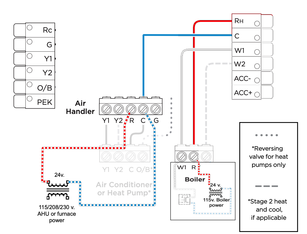
See how this R and C connections are going to two different transformers? That not going to power anything. The source 24 v. transformer is different from the Return Path transformer. No completed circuit here**********************************************************************************The smart thermostat's (CPU) central processing unit (computer) gets power fromRcandC. So this next diagram will also not operate the thermostat.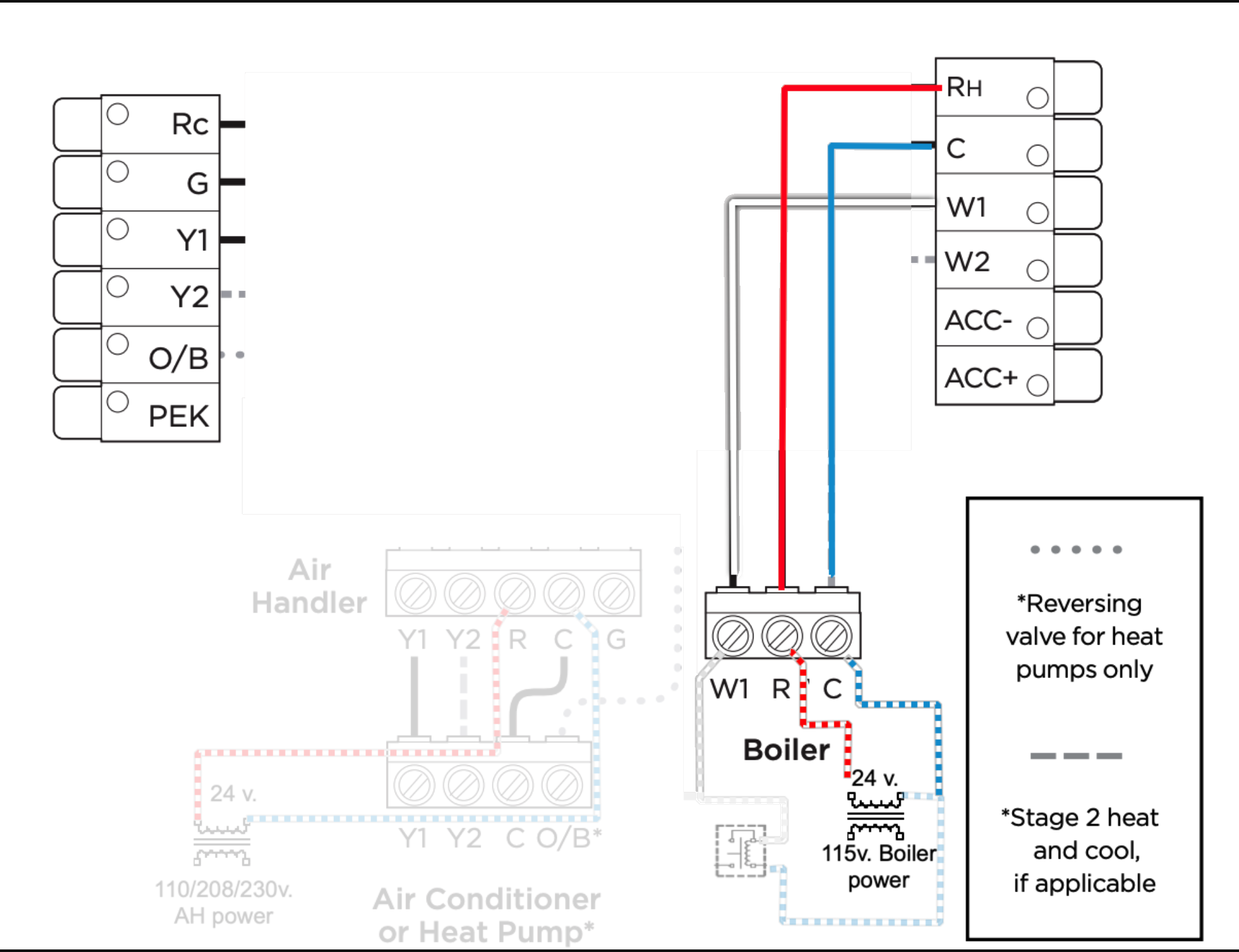
The reason this wiring configuration will not work is the Rc does not have power to operate the thermostat's CPU.*******************************************************************************The correct heating only wiring for most smart thermostats is this diagram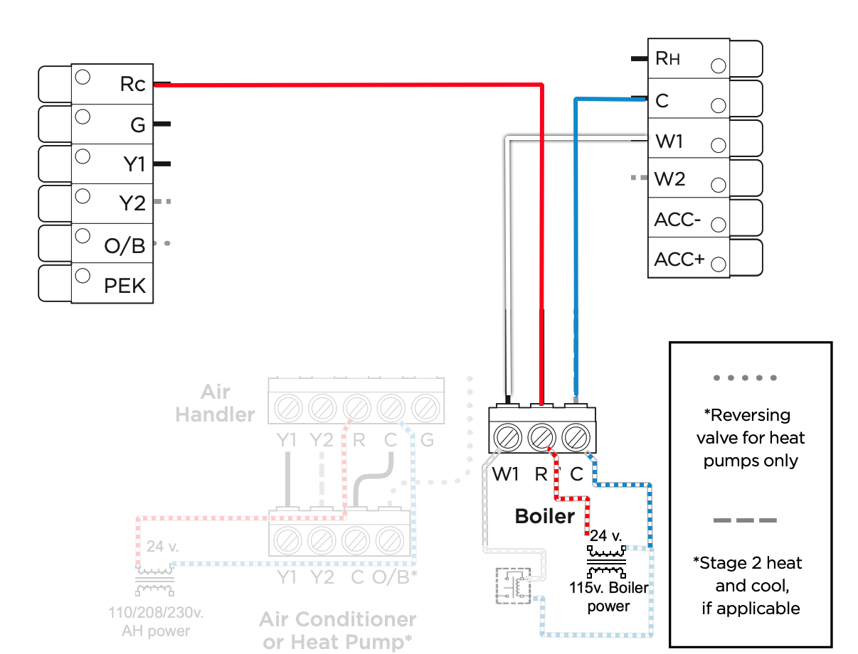
With this wiring configuration there is power to the smart thermostat's CPU. Now the brains of the thermostat can figure out that the thermostat is connected to a heating system that needs Rc to W in order to make the boiler or heating only furnace to come on.*****************************************************************************The only time you need Rh in most smart thermostats is when you have an air handler system that might be cooling only and a separate heating system like a boiler for hot water or steam heat. Then you need to isolate the two different transformers. That is the function of the Rh terminal on any thermostat. Make sure the Air Conditioner's 24v. control transformer does not connect to the heater's 24v. control transformer. This diagram illustrates that point.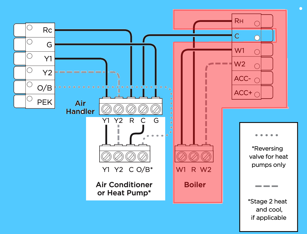
The Blue and White areas represent the air handler or furnace side of the thermostat. Once you connect a wire to the Rh terminal on a smart thermostat the thermostat's CPU recognizes that and creates a kind of a firewall to separates the heating only section in the Red area from the rest of the system in the blue area, within the thermostat.Without the Rh wire connected then the thermostat's CPU does not form the firewall and the Rc will be able to operate the heat burner thru the W (and W2 if needed) like you would find on a regular Gas furnace, along with all the cooling and fan systems/relays.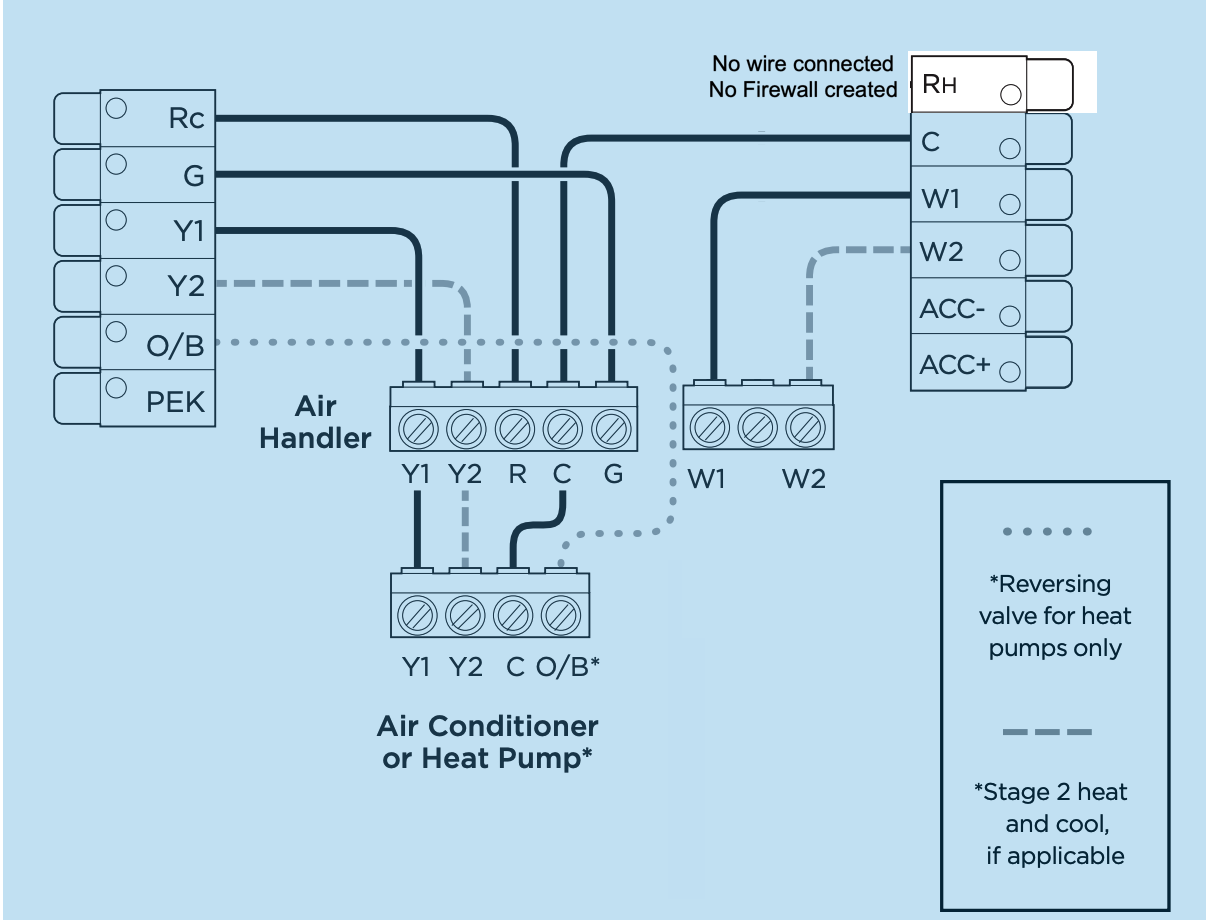
Edward Young RetiredEdward Young Retired
After you make that expensive repair and you still have the same problem, What will you check next?
1 -
This past month I assisted several using private message and I just wanted to save the wiring diagrams so I can find then in the future.
Steam with Nest
Add on Hydro coil for heat on variable speed air handler using a ZVC 404 for the zone valve control
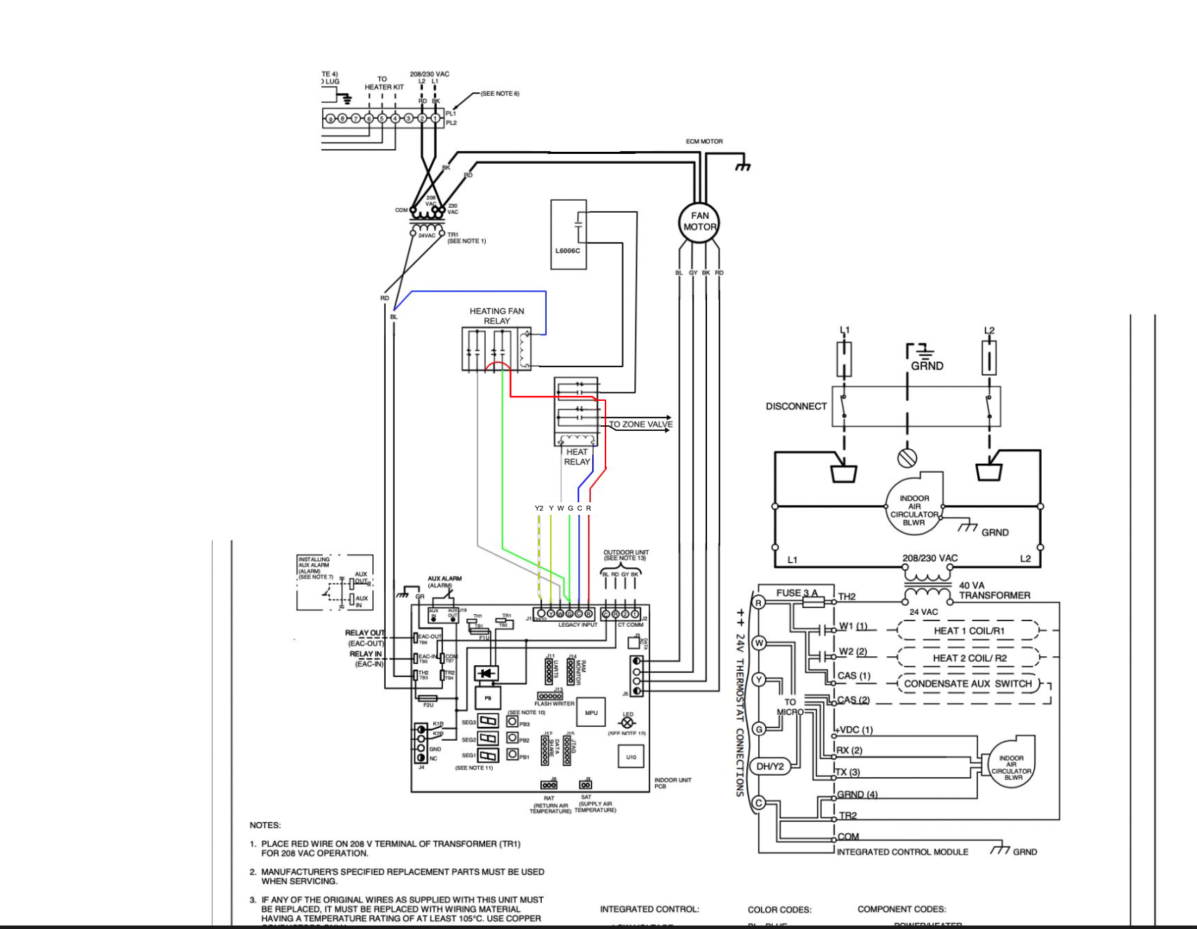
This diagram uses the Heat Relay C an NO contacts to operate a zone on the ZVC 403. (Not powered) like an end switch.
There is a similar diagram that uses the 24v. transformer from the air handler to operate the zone valve.
Same concept but the zone valve is powered differently. we are looking to fool the variable speed fan by using the G and the W on the AHU control PCB to get both a call for heat and a call for fan simultaneously. Otherwise a call for fan only (G) may indicate that variable speed fan to operate at a 10% or 15% IAQ filtering speed which will not be enough to circulate heat from the Hydro coil to the conditioned space. Any questions? just ask me.
Edward Young Retired
After you make that expensive repair and you still have the same problem, What will you check next?
 1
1 -
I'm often asked about VENT DAMPER INTERNAL WIRING
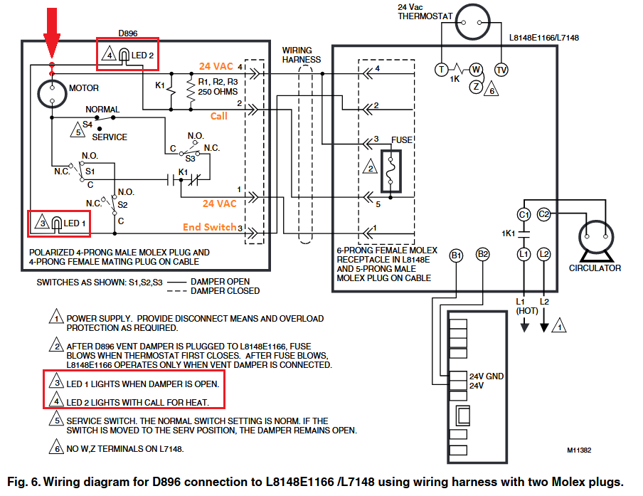
The best diagram I have on the internal of the auto vent damper, and this is from a long time ago (not the current Fields/Effikal version) is this one:
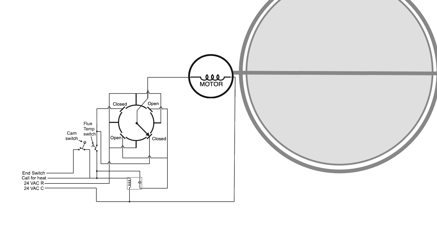
The motor stops at each 90° turn of the motor. 90° to open, 180° to closed, then 270° to open, then 360° = 0° to close. There is constant power needed to operate the motor to close the damper after the call for heat is satisfied. @EBEBRATT-Ed has the correct wiring description
- Constant hot 24v from transformer "
R" Black wire to #1on the damper - 24 volt common from transformer "
C" Green wire to #4on damper - #
2on damper yellow wire to 24v on ignition control (starts burner) - yellow at damper. Starts at "
R" red on transformer through limit and operating controls to damper #5
There is a 6 Pin Molex on the control that the damper is attached to in order to prevent Bubba from placing the jumper plug back on the control while there is a broken damper installed in the flue connector between the boiler and the chimney base. There is a fuse placed between pin #
3and #5on the Molex mounted on the control. The factory installed jumper connects pin #2 and #3 in order to complete the “End Switch” circuit when a vent damper is not used. when a damper is connected the 6 pin has on more wire that @EBEBRATT-Ed did not include. the green wire (24v. hot orR) is connected to pin4andpin3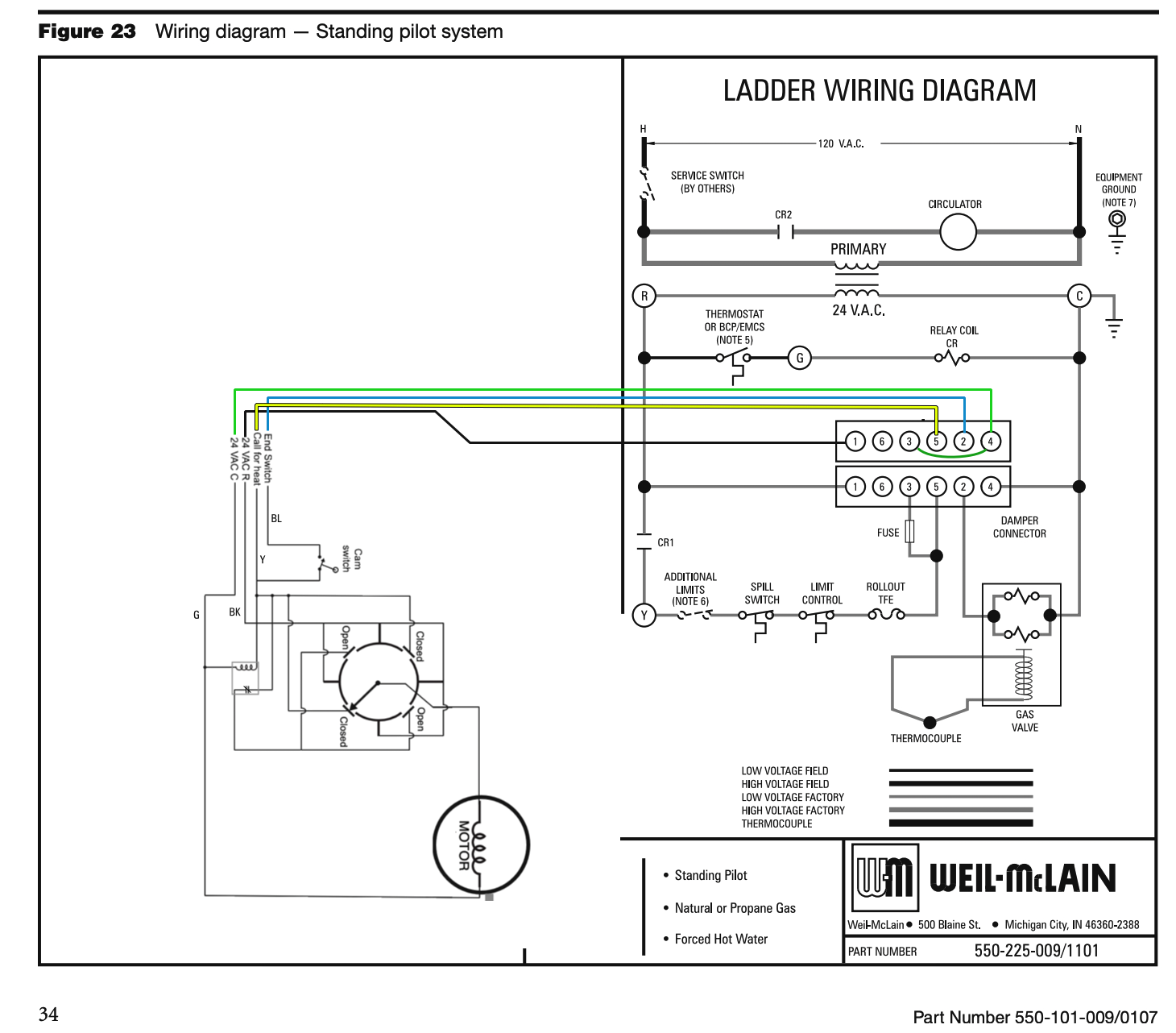
Imagine Bubba at the service call: This has happened more than once before this wiring design was made standard. No heat and the vent damper cam switch (end switch) is the problem. So, Bubba jumps the switch to get the burner to operate and locks the damper in the open position (because he is too lazy to remove the damper) and you have heat. Later someone sees that the damper is locked open and does you a favor by removing the bracket that is keeping the damper from closing in order lower your fuel bill and save you money.
The next call for heat the damper gets stuck closed but the cam switch is jumped and the burner operates with a closed damper. The next day there is a big news story about carbon monoxide poisoning. In the 1970’s this was not just a one off story but something that happened enough times to cause a new standard wiring design using that special connector cord with a 4 pin on one end and a 6 pin on the other end Here is how that works.
- No damper = jumper from
2to3 - Add a damper and the first time the damper opens power gets sent to
5and3 5powers the burner circuit and3gets a direct short to the transformer and the fuse blows between5and3- Now the jumper from
2to3will no longer work on that control
Now if the factory installed
"No Damper"jumper is put back in the control, after a damper has been installed and wired in, it will no longer work since the fuse between5and3is blown. This keeps Bubba from just putting the jumper on the control to get heat without doing some real serious rewiring and maybe even removing the damper from the flue connector pipe.I need to add this one to my "How Do I connect This Wire?"
How it works one step at a time
Take each circuit one at a time if you want to understand it.
Everything in Red is powered and the blue is the return path to the transformer. The purple Is the path from the rotary switch arm to the hot side of the damper motor.
The switch arm in the closed position has no power until there is a call for heat
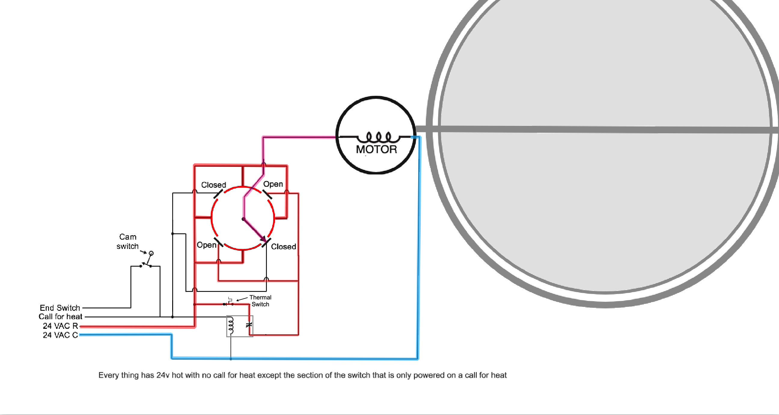
That call for heat causes three things to happen (See Orange wires). The Closed contacts get power to start the motor. A relay coil causes the power to the Open section to the rotary switch to lose power and the motor then reaches the “Always Hot” portion of the rotary switch so it continues to operate until it is completely open.

When the motor reaches the full open position the motor stops since there is no power to the Open contacts on the rotary switch. Also the Cam Switch (End switch) closes sending power to the burner circuit (Green wire).
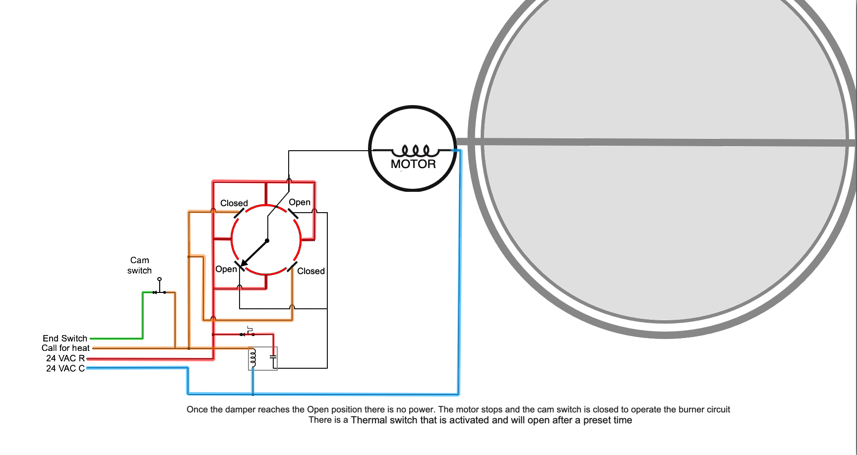
The burner operates safely with the damper open. Eventually the call for heat or a limit stops the burner.
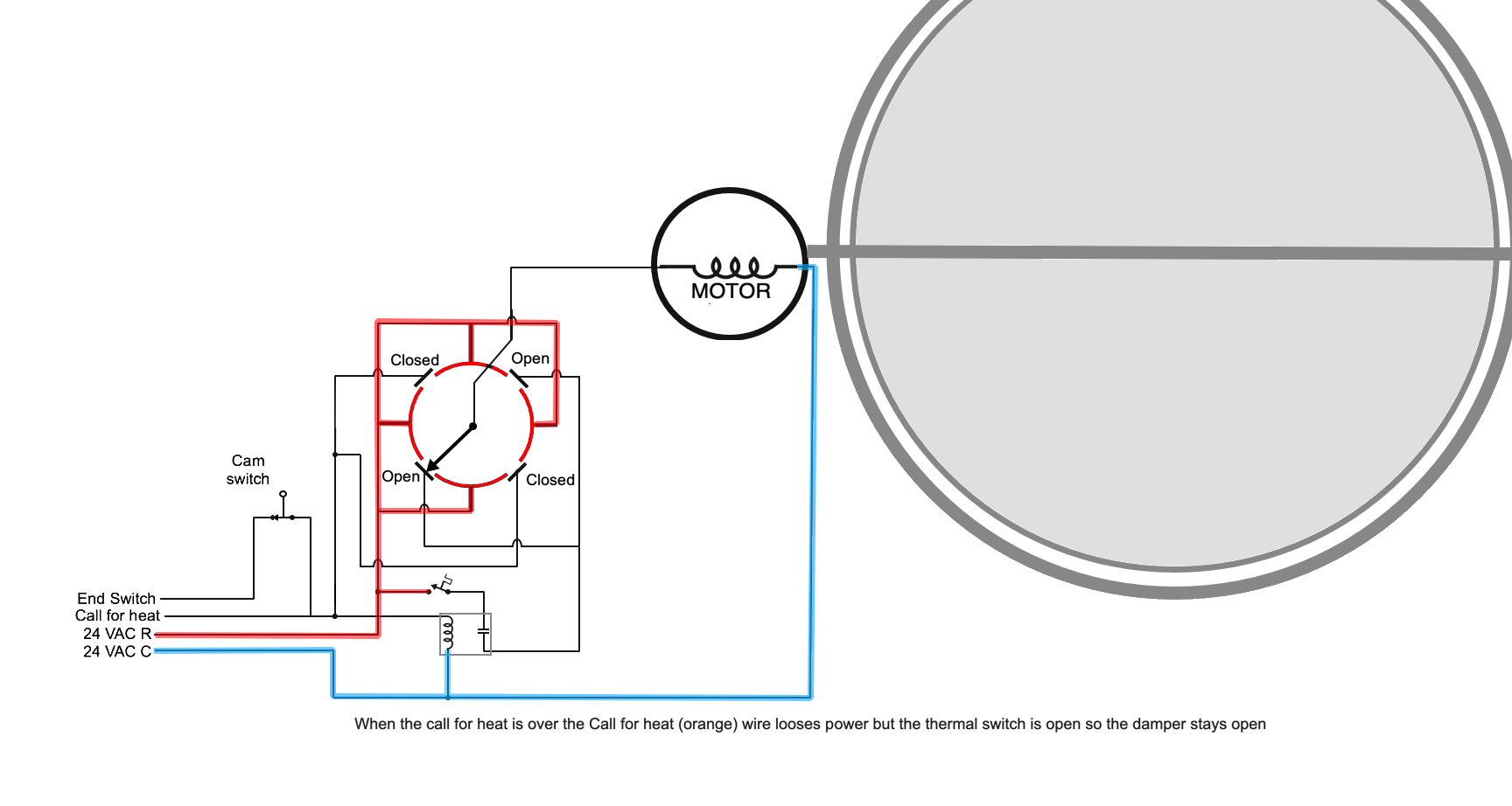
The orange call for heat looses power and the green to the burner looses power but the thermal switch may keep the damper open for a time in order to clear out the byproducts of combustion from the boiler or furnace.
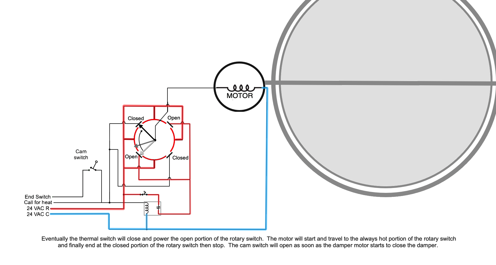
Eventually the thermal switch will close and power the open portion of the rotary switch. The motor will start and travel to the always hot portion of the rotary switch and finally end at the closed portion of the rotary switch then stop. The cam switch will open as soon as the damper motor starts to close the damper. EBEBRAT-Ed found this diagram in the instructions from 1995 and 109A_5 fixes the error on the diagram
Edward Young Retired
After you make that expensive repair and you still have the same problem, What will you check next?
2 - Constant hot 24v from transformer "
-
This is going to be a chapter in my book:
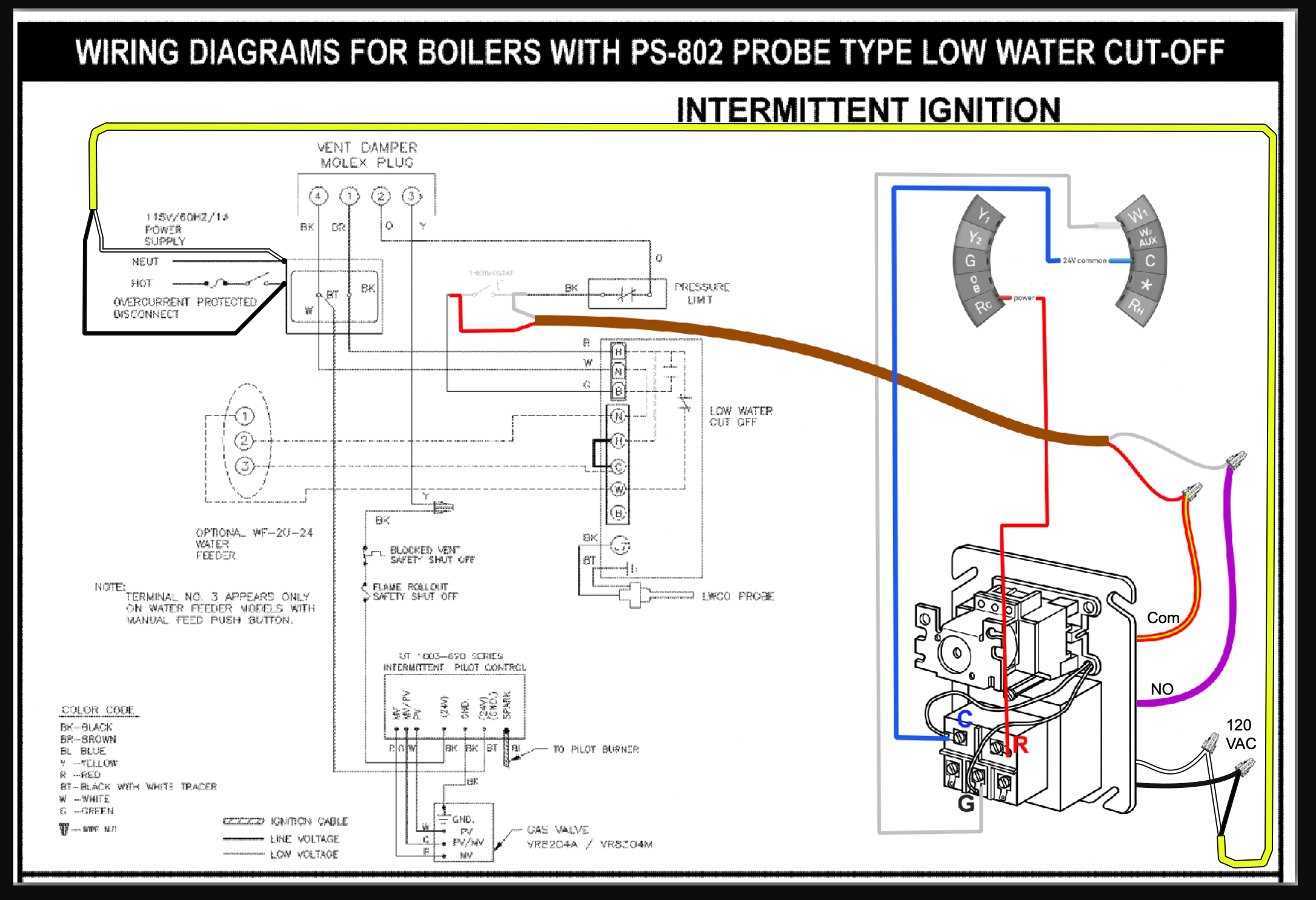
Adding a Smart Thermostat to a Weil McLain Steam boiler. the easy is to use an isolation relay but I ended up having a discussion with a homeowner about doing this without the isolation relay:
This is a 30 minute class that reviews the electric circuit basics and continues to the rewiring of the electronic LWCO in order to connect the R from the smart thermostat directly to the R on the Weil McLain transformer
Edward Young Retired
After you make that expensive repair and you still have the same problem, What will you check next?
0 -
"This is going to ba a chapter in my book:" This is fun! 🤩 When do you expect to have your book? No doubt you know the book publishing world is an interesting and diverse place. About a title, or working title … Maybe "How Do I Connect This Wire?" … subtitled, "Keeping the Smoke In" 😁
Yours, Larry
0 -
Your book!!?? YES!
0 -
Keeping the
(Factory Installed)
Smoke In
This was the title that Larry Weingarten suggested when he sent me a copy of his book The Philosophers Wrench. The SMOKE refers to the nasty smell and uneasy feeling that you get while diagnosing an electrical problem and somehow there is a small puff of smoke that enters the air in the boiler room as it is emitted from a very expensive control. Some of us like to call that the Factory Installed Smoke on HeatingHelp.com.
I have a knack for wiring analogue controls on all types of HVAC systems. After over 40 years of diagnosing problems with air conditioners, heat pumps, boilers, and all types of zone controls I have been asked to solve some pretty interesting problems. Taco 570 series zone valves are a common headache for plumbers that know how to put pipes together for boiler systems but often lose their whole day of productivity when the zone valves need to be wired in, and the electrician on site has no clue about low voltage controls.
So here I am putting my experience and knowledge into a book with lots of pictures and diagrams so those with a little less self confidence in their control wiring skills, may have an easy reference guide to look at on the job. There will be no real order to the different topics however there will be an index in the back so you can quickly find your specific wiring problem and the necessary diagram to solve it.
When ready, Larry I would like you to proof read it and perhaps write a little something for the beginning of the book. (what ever ya' call that part of a book that no one ever reads)Edward Young Retired
After you make that expensive repair and you still have the same problem, What will you check next?
 2
2 -
Hi, This IS fun! We're all gonna get a book to keep us out of burning trouble! I'm honored to be asked to write some words for early in the book someplace. Of course, though there are others here who's names I'd like to see in your book. Have you considered creating what's called a support group for your book? It could be people from HH who would give you their slant and feedback on what you've written. This is very useful for uncovering potholes in flow or understanding. And it all must be done with humor somehow! People learn five times faster when having fun. This just FORCES you to write with humor 🤡🙀
Yours, Larry
0 -
I only have 5 chapters so far and I think I need to cover much more. I have a feeling that there will be at least 10 chapters, maybe even 20 chapters, one on each of my ideas, Zone Valves, Smart Thermostats, and Controlling primary secondary systems and two temperature systems are what aspiring mechanics need.
My first chapter is the basics as I understand them. It starts out with "if you already understand how electricity works skip to chapter 2. The next sentence then goes to the basic electric circuit with 4 parts: Source, Load, Control(s),and Return Path. That is the basic minimum to actually use electricity. You need a source and you need a load. And you need a way to get the power to the load and a way for the power to complete the circuit to get back home. I touch on ohms law and really basic stuff that I thought was interesting when I learned about it years ago.
I like the idea of having a group of people help me with this project. That is a great idea. If for nothing else than to look for misspelled words, mistaken diagrams and for people to tell me how to say what I mean and not what I actually say!
I just caught a mistake in the diagram I posted earlier and fixed it which made me think that I may have told someone the wrong terminal to connect a wire to. I hope I corrected it in time.
Thanks for some great ideas Larry!
Edward Young Retired
After you make that expensive repair and you still have the same problem, What will you check next?
2 -
Nice and thanks!! Already meddling here … how about a discussion of tools and how to use them for this sort of electrical work? Many people just don't understand the need for good tools, or even know what they are. Another thing is making no assumptions. I've found the green wire as the hot. Can't assume people knew or followed convention. Anyway, good work! 🙏
Yours, Larry
1 -
Sign me up for one of the first editions!
1 -
Me too!
All Steamed Up, Inc.
Towson, MD, USA
Steam, Vapor & Hot-Water Heating Specialists
Oil & Gas Burner Service
Consulting0 -
@EdTheHeaterMan So happy to hear you are actually doing it. It was maybe a year ago that you spoke about doing it. ( I always thought you should write a book.)
I'll take a look at some of your stuff during your writing and will be certain to purchase a copy when its done.
Twenty chapters. Sounds like a good amount.
A chapter dedicated to old forgotten ways and new ways to trouble shoot, and new ways to trouble shoot with new tools sounds like something to add. @Larry Weingarten made me think of that one.
Looking forward to it's release.
1 -
Well I am WHELMED with this response. I can't say overwhelmed since there are only four of you responding. Now if it were maybe eight of you then I might be overwhelmed but for now I am just whelmed. And I thank you all for your encouraging responses. I added another chapter today. it has to do with the old ways…. here is the first paragraph:
Chapter ? old forgotten ways
And new ways to trouble shoot, with new tools
When this idea was presented to me by a member of HeatingHelp.com this memory came jumping back to me. When I was a wee lad and Dad brought me to work on a Saturday, My job was to sweep the yard and empty the trash cans. I was able to meet the different employees and I remember a service technician named Howard Levy (pronounced Lee Vee) who had an index finger that was partially missing. Howard would test the electricity on a control or in a light socket with the index finger stump by touching the metal conductor. If he did not feel the current tingle on his finger, then he would put his finger in his mouth to get it wet for a better connection, and try again.
“Yep the switch is on. Can you go over there and shut the switch off so I can work on this control wiring?”
Let's see how this goes.
Edward Young Retired
After you make that expensive repair and you still have the same problem, What will you check next?
3 -
Ed, I know I only count as one who already voted, but story telling is what makes for a great book. Dan tells stories and they work! You just told a compelling story that draws us in for what's next. 🤩👍️
Yours, Larry
2 -
A chapter the ins and outs of thermostats. Including using power robbing thermostats, or not using them.
2 years ago I did a cleaning on a steam boiler. And the elderly woman told me that her thermostat was too high it was an older Honeywell round. And she wanted to move it down but it was already falling apart so I told her I would replace it with a new one that was not that expensive so I did. I positioned it at eye level and she loved it the heat came on and everything was fine. The next morning I get a desperate call that "my house is freezing". I get there and there's no call for heat from the thermostat. So I learned about power robbing thermostats. I replaced it with a Honeywell mechanical which is no longer round but square and isn't as easy to read as the round. (She did not want anything with batteries)
1


Categories
- All Categories
- 87.6K THE MAIN WALL
- 3.3K A-C, Heat Pumps & Refrigeration
- 59 Biomass
- 430 Carbon Monoxide Awareness
- 124 Chimneys & Flues
- 2.2K Domestic Hot Water
- 5.9K Gas Heating
- 120 Geothermal
- 168 Indoor-Air Quality
- 3.8K Oil Heating
- 78 Pipe Deterioration
- 1K Plumbing
- 6.6K Radiant Heating
- 394 Solar
- 16K Strictly Steam
- 3.5K Thermostats and Controls
- 56 Water Quality
- 51 Industry Classes
- 50 Job Opportunities
- 18 Recall Announcements