Another Smart Thermostat Question

Hey, Guys!
I'm sorry but I have to ask another smart thermostat question. Last year, I followed someone's diagram. It's hazy but I remember that it wasn't the optimal solution, but it did work.
However, for the past few months, the thermostat gradually got worse. First, it would occasionally turn off by itself. And, now, for the past month, it happened even more frequently. Starting from yesterday, the smart thermostat reboots about a minute into the heating cycle.
I'm guessing that my c wire is connected to something that drops in voltage immediately after the heat turns on. (I'll go test it in a minute to confirm but wanted to post this question first.)
For the past hour, I've been scouring this forum to find the correct solution, the one that has a constant power source. Does anyone know which one it is or can tell me what I need to do?
This is my equipment:
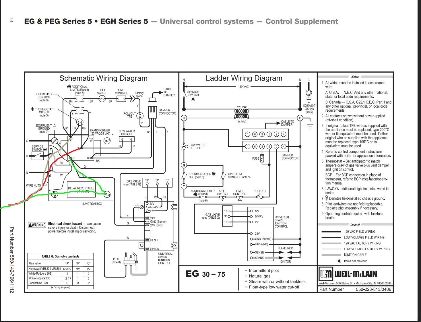
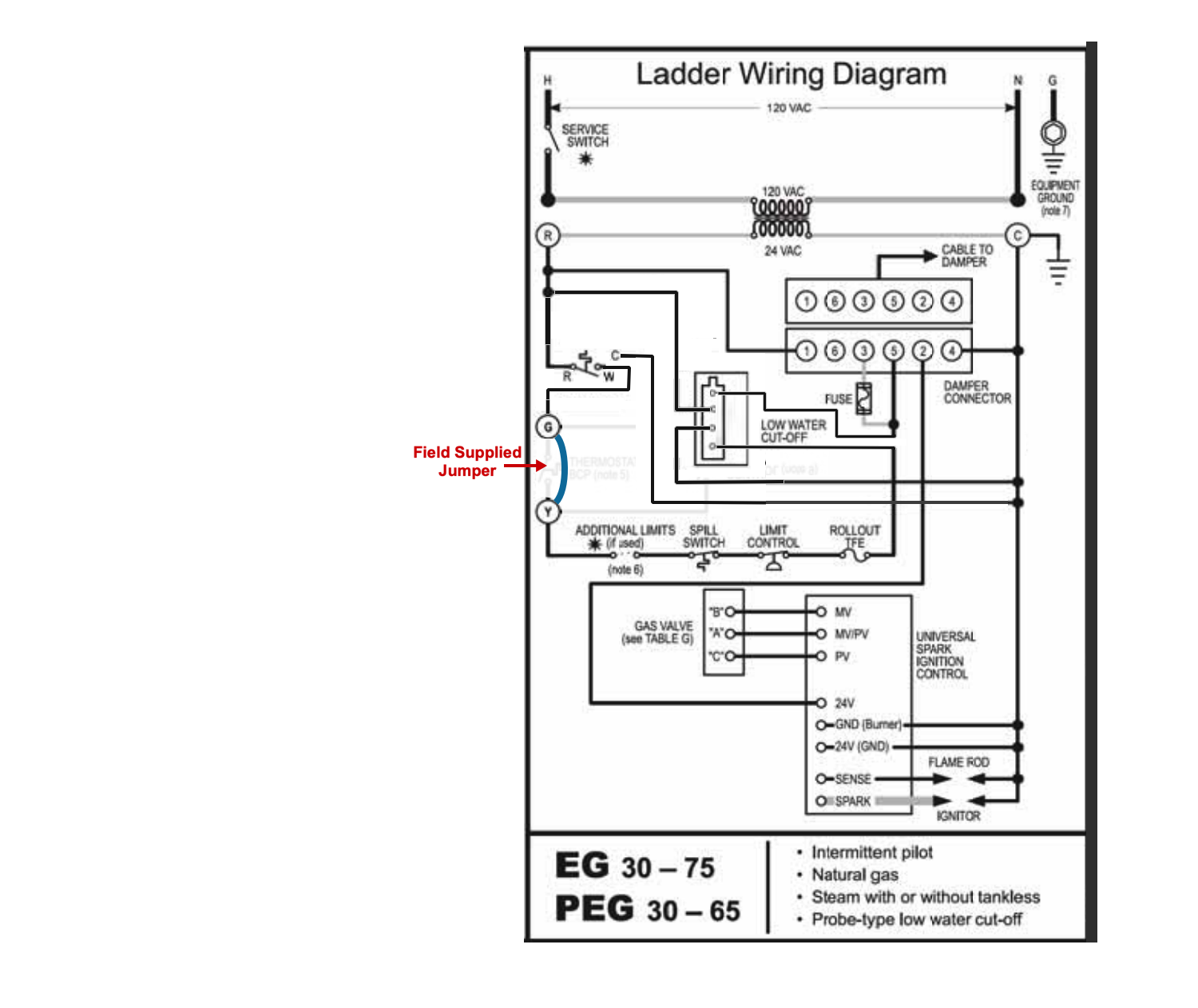
- Weil McLain EG-35
- ecobee Smart Thermostat Enhanced
- transformer
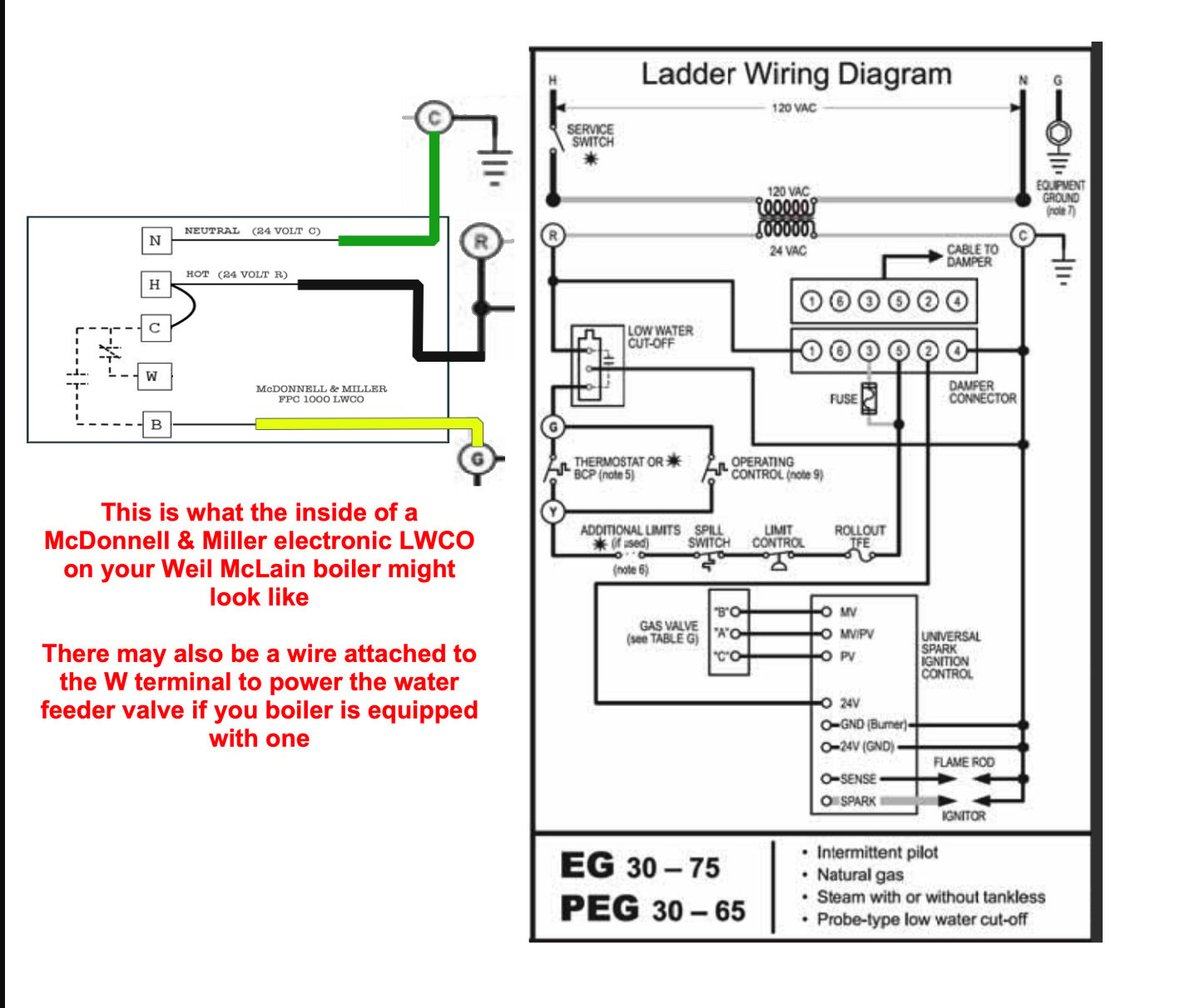
I have a transformer but I ended up never using it last year. I'm not sure but I think I followed this diagram from a post here.
I pretty much followed this diagram. I even plugged the common wire into a screw in that exact location.
I guess my first question is whether this is a C wire issue and not something on the boiler side. I checked the boiler and it doesn't seem like it.
Can I simply plug the c wire into something more stable? Or do I have to use the transformer to provide a steady power supply?
Comments
-
I checked the voltage with my multimeter.
The R-C line stays constant at about 27.9V before the call for heat, during the call for heat, and after the short cycle.
The W-C line is about 2V before the call for heat. During the call for heat, it goes up to about 27.8V. When the boiler short cycles, the voltage drops to about 4V.
Given the numbers above, am I right that the thermostat is broken?
What's strange is that it seemed that the boiler would cut off when there was the slightest heat/pressure built up. So I was worried that a pressuretrol was broken or something and it was setting off a short cyle. But if that's the case, the voltage on the R-C line would drop, right?
Since the R-C line's voltage is always constant, the thermostat must be broken, right?
0 -
Thermostat may or may not be broken. R-C should always be about 24 to 27 volts, so you are good there.
Br. Jamie, osb
Building superintendent/caretaker, 7200 sq. ft. historic house museum with dependencies in New England0 -
Jamie,
Can I ask you a quick question? Right now, my house is 60° because of the short cycling. Can I just connect the R and W wire to call for heat? Then when the house is all warm, just disconnect them?
Just want to make sure I'm not going to short anything. I know I can't jump the R-C nor W-C. I guess I'll just turn off the power, then connect R and W with a wire, and then turn it on?
This will also definitively prove whether it's the thermostat or the boiler.
0 -
I guess nobody is back home from work. ☹ It's ok. I'll just talk to myself. 😃
I jumped the R-W line so the boiler just turns on indefinitely. I'm such a newb that it took me an entire day to think of this. The house is finally getting warm.
I'm thinking this result demonstrates that the boiler was fine and it was definitely the thermostat. The only other possibility is loose wires between the thermostat wires and the thermostat. Since they weren't loose, I'm guessing it definitely was the thermostat.
I've been on hold waiting for an ecobee rep for hours, so I can file a warranty claim. Before I bought this, I read a lot of complaints about ecobee's customer service. They weren't lying. It's hard to get through. And when you do, they jerk you around because they don't want to send you a replacement.
Enjoy the weekend, folks!
0 -
That may be an @EdTheHeaterMan diagram. It's too good to be one of mine.
0 -
@MrVince That is my diagram. I need to know if you used Rc or Rh for the Red wire from the R on the transformer to the R wire on the Thermostat. The thermostat needs to see 24v. at Rc and C to operate properly. If you used Rh because it is for your heater you may have a problem. The only time you use Rh is if you have a separate air conditioner with a separate air handler transformer. Then the Rc and C comes from the air handler transformer. Does your thermostat also operate your air conditioner?
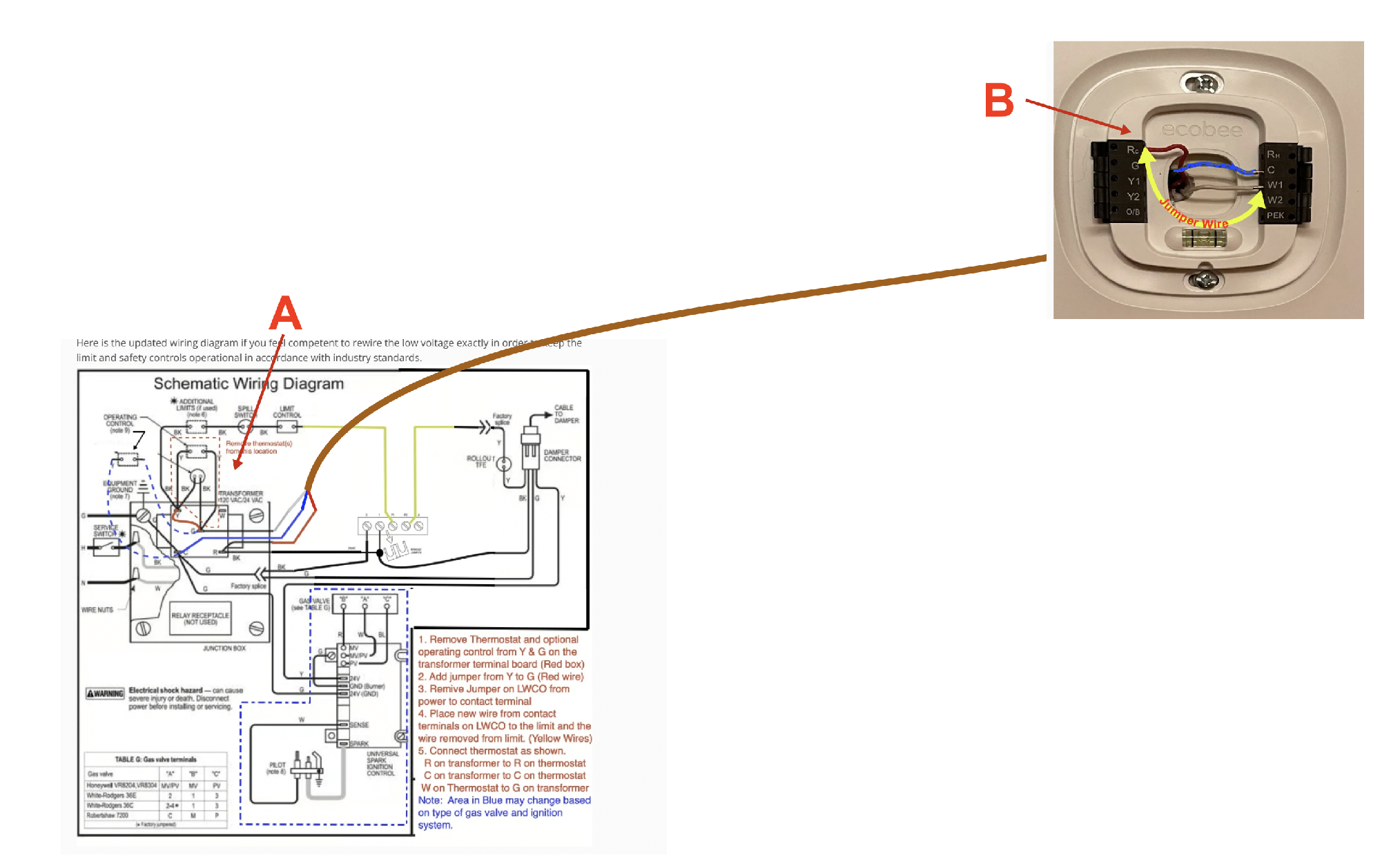
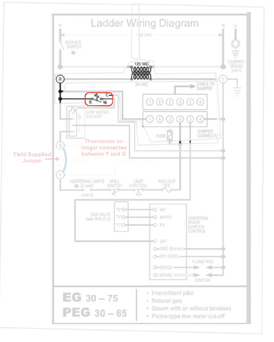
If you are using Rc and W and C on the thermostat, for heat only, then there is one more test to try to rule out the thermostat. I have moved the thermostat on the diagram to make the test clear. I am guessing that you jumped R and W at the boiler location as in the A position on the diagram. Now try the B position on the diagram. Put the wires back the way they were and put the R to W jumper on the terminals at the thermostat location upstairs. That test will rule out the wiring between the thermostat and the boiler.
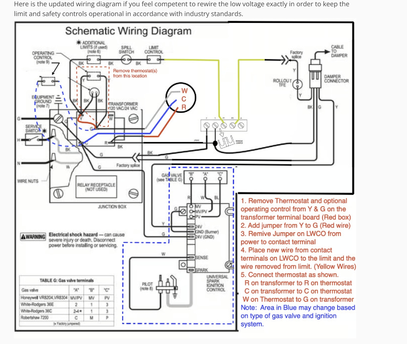
I also want to say that the diagram shown is not the way it is on the boiler or in the manual. The LWCO is connected a little differently. It is described in the red text in the lower right corner. You said "I pretty much followed this diagram." I would rather you say "I followed this diagram exactly. If you did not follow that rewire and then test the LWCO and all the other safety and operating controls to be sure they are operating properly, then you need to double check every connection from one end of each wire to the other. Also make sure the factory installed jumper from 1 to P1 on the LWCO is removed.
I hope this helps.
Edward Young Retired
After you make that expensive repair and you still have the same problem, What will you check next?
0 -
Sorry for the delay. A lot of issues, involving both this thermostat and work, came up. Unfortunately, I'm still dealing with this issue.
I didn't combine it exactly as in your diagram. I downloaded the exact wiring diagram from my manual and marked the exact connections made.
R (red wire) is connected to Y on the transformer.
W (white wire) is connected to G on the transformer.
C (green wire) is connected to a screw on the mounting plate. (In the diagram below, the screw is in the upper left corner but in my actual boiler, the screw is in the bottom right. I'm guessing it doesn't make a difference but I wanted to be completely accurate in case it did.)
I notice that the connections are very different than the ones in your diagram. I know that several professionals suggested to do it the way I did it. Is your way "better"?
I'm still trying to isolate the problem. It appears that the voltage drops about a minute or so into the heating cycle first. The voltage drops from 27V to about 1V for about 2 seconds. Apparently, this is enough that it resets my Ecobee smart thermostat. After it reboots, it calls for heat again. The heat turns on for about a minute and then the voltage drops again. (I think this is what's happening. I'm still trying to replicate everything.)
Do you know what's happening and what I could do?
0 -
I notice that the connections are very different than the ones in your diagram. I know that several professionals suggested to do it the way I did it. Is your way "better"?
YES
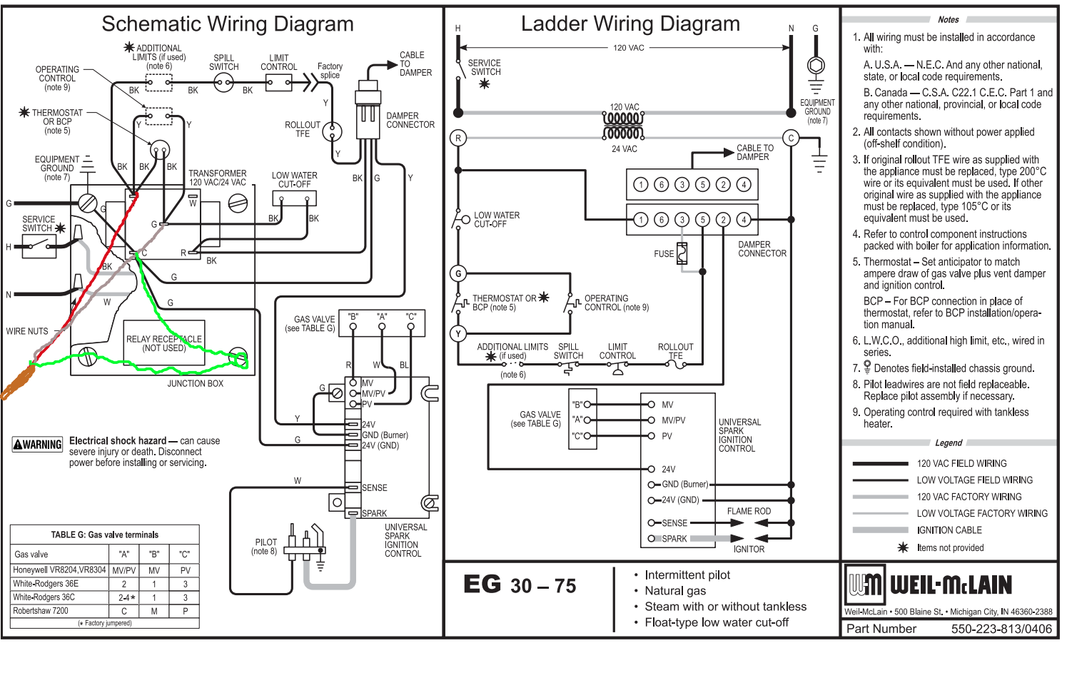
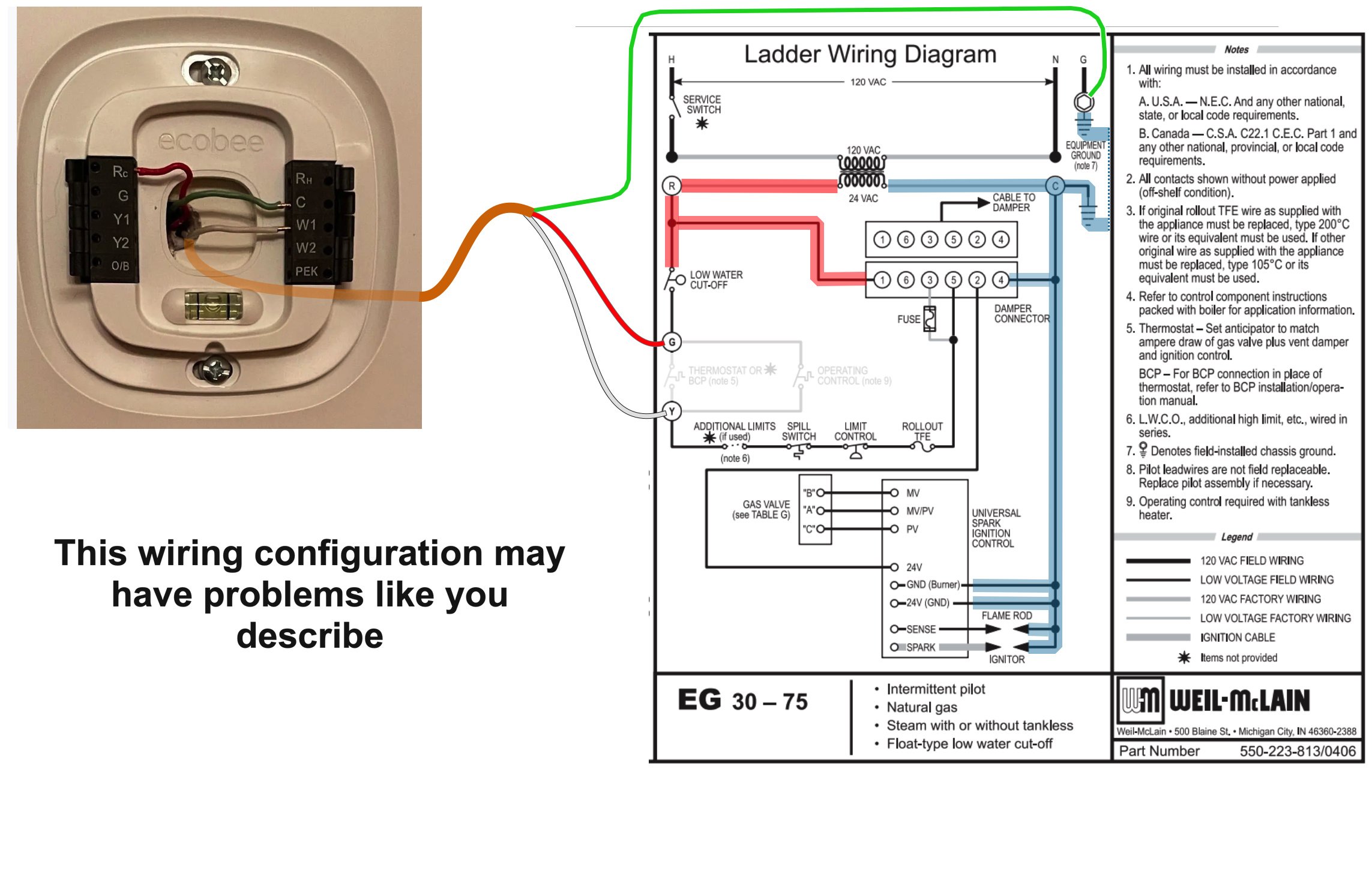
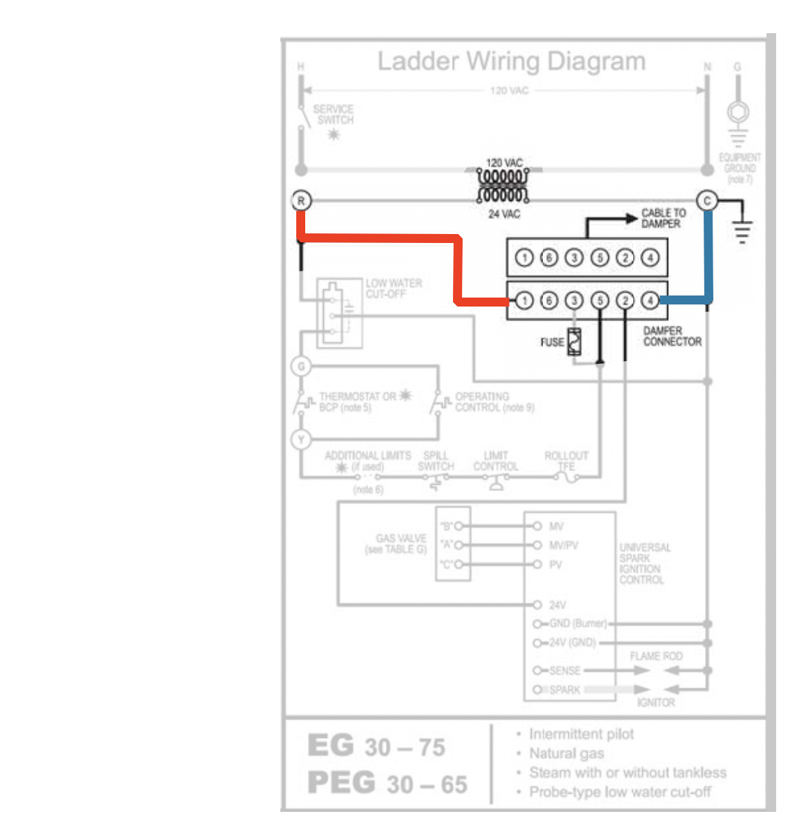
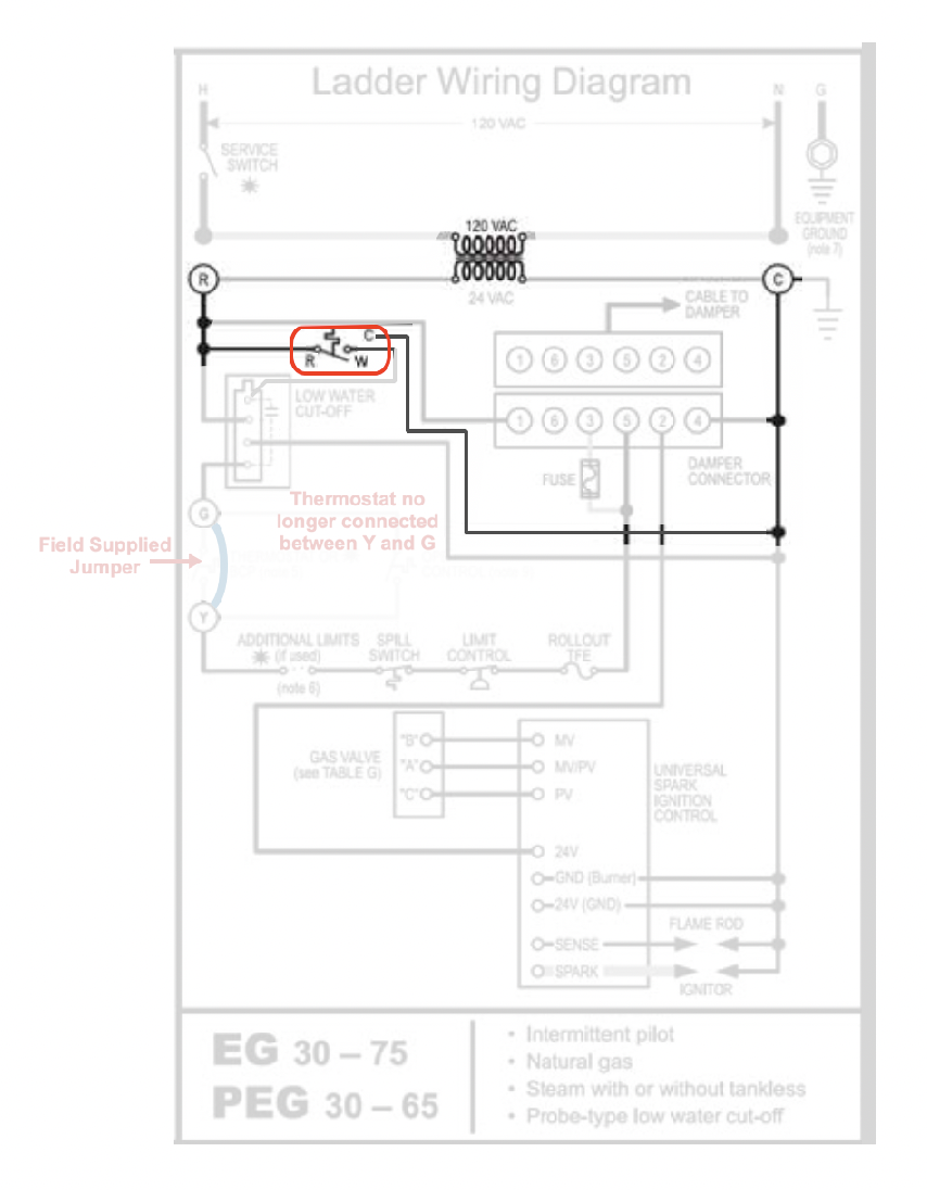
I have moved your Red White and Green thermostat wires to the Ladder Diagram here
The ecobee wants to be connected Rc from the thermostat to the transformer R terminal and C from the thermostat to the transformer C terminal. It appears that the Rc from the thermostat is connected to the Y on the transformer. Take a close look at the Y terminal on the transformer. It is not electrically connected to the transformer anywhere. It is what we call a blind terminal. Think of it as a wire nut only. Not a transformer connection at all.
If you were to connect the thermostat W to the Transformer Y then place the thermostat Rc on the transformer G You would be a step closer to the R on the transformer. As long as the LWCO never opens as a result of a low water condition in the boiler, then the thermostat Rc will be connected to the transformer R thru the LWCO.
By the way, what LWCO is on your boiler?
When the LWCO opens for a low water condition in the boiler. the thermostat Rc will no longer be connected to the R on the transformer That may cause you some problem. The easies way to correct this is to use an isolation relay with a separate 24 V Power source. But if you feel confident with your wiring skills and can follow the diagram I provided, you can power the ecobee, the Automatic Vent Damper, and the LWCO with the same transformer.
This diagram has the ecobee, the LWCO and the Auto Vent Damper all getting power from the R terminal on the transformer. That is a must when connecting any smart thermostat. An uninterrupted connection the the R terminal on a transformer and the C connected to the C of that same transformer.
If your LWCO is an electronic probe type, then you must rewire it as shown in the diagram and removing the factory installed jumper from the #1 terminal and the P1 terminal, or the equivalent terminals thereof.
Edward Young Retired
After you make that expensive repair and you still have the same problem, What will you check next?
0 -
Thanks for your help!
I'm sorry. I made a mistake on my diagram. I incorrectly drew the R with the Y when it actually is with the G. And the W with the G when it is actually with the Y. Below is the way I actually connected it.
But I'm going to rewire my boiler to your exact configuration. You sound like you know what you're doing. 😆 Give me a few hours/days because it looks like a lot of work. 😉 I'll let you know how it turns out. I'm pretty sure I'll have questions along the way.
I'm curious though. I noticed a few people saying to connect the R wire to the G, and the W to the Y (the way I did it)? Like this guy:
https://www.youtube.com/watch?v=1sPJC71hwQ4
Is that one way to do it but it's wrong? I noticed a few other people do it like this.
What happens with me is that when the Ecobee calls for heat, it connects the R and W wire, right? I'm guessing that the increased load caused by the W wire causes the Ecobee thermostat to lose power. That's just a guess though. I can't figure it out. I was about to test the current and see if the current changes. The voltage from the R never changes. It stays rock solid throughout.
0 -
- on yeah. You asked what type of low water cut off. I have a probe-type with an automatic refill with a meter.
- Is the dashed blue wire on the left the emergency shutoff switch that was removed in the dashed brown area?
- Is the thermostat the circle in the middle?
I have wago connectors so it's not too big of a deal to rewire everything. I just want to make sure that I do it correctly. How do I know if the dashed blue area on the bottom right is going to change? Below is the type of steam boiler I have.
Would it be easier if I added an isolation relay or something else?
0 -
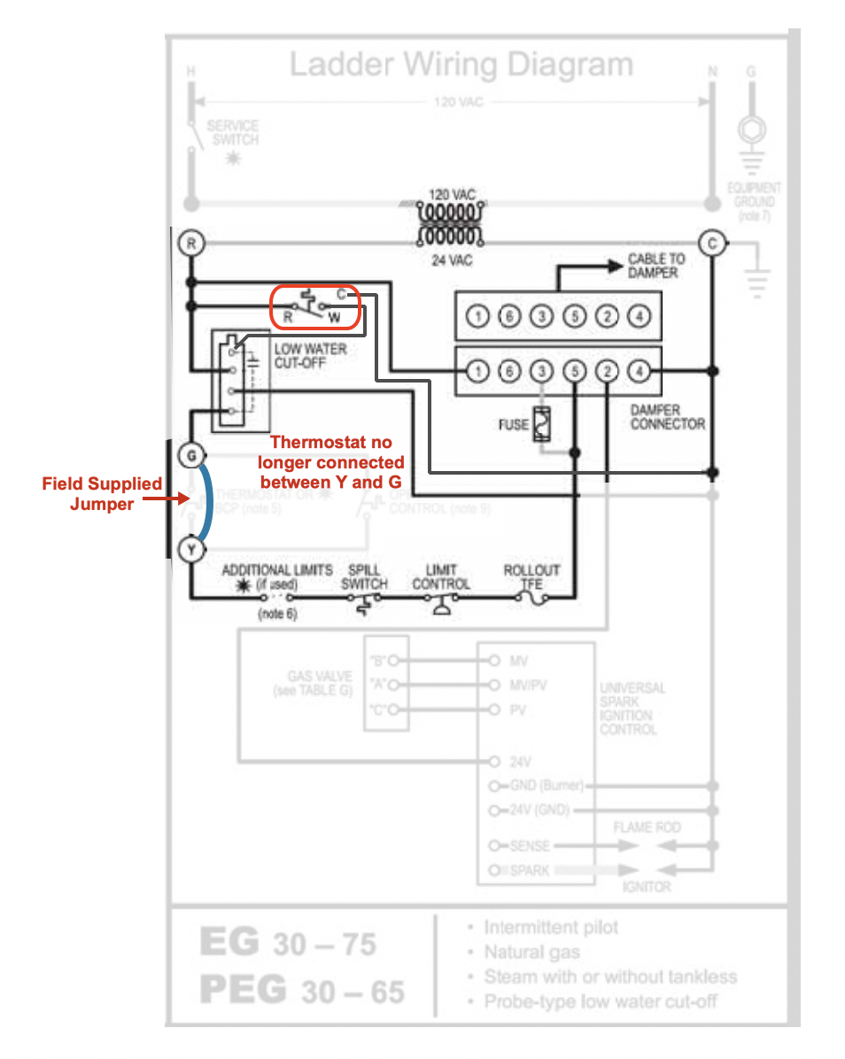
I watched the video and that wiring may work with some thermostats. I have made the correction you indicated and it does match the wiring that is described in the video. RED HIGHLIGHT is from the R side of the boiler transformer as it is connected to each component thermostat, LWCO and Vent Damper. BLUE HIGHLIGHT I the Common from the boiler transformer to all the C connections of the thermostat, LWCO and the vent damper.
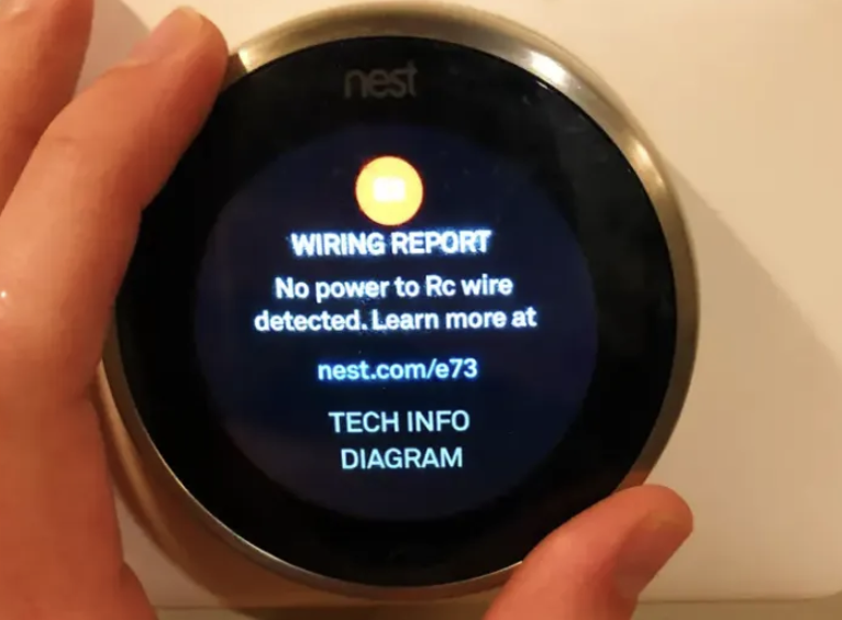
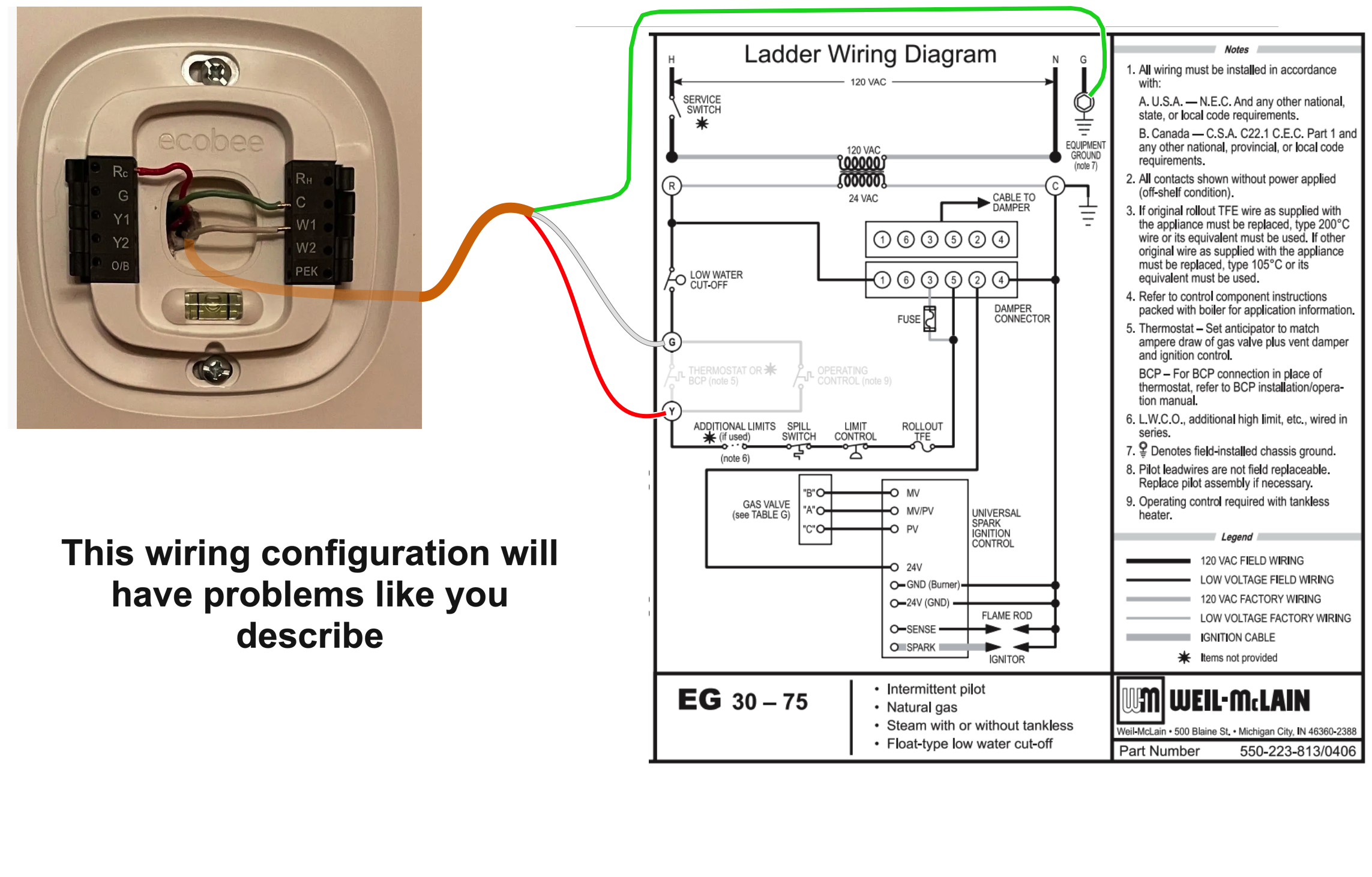
Where some thermostats have a problem is when the LWCO opens as a result of a low water condition. You can clearly see on the ladder diagram above that, the transformer inside the boiler is wired to the R terminal and the C terminal on the transformer. this actual diagram does not show how the rest of the LWCO is connected. It does show that the R from the transformer is not directly connected to the R, Rc or Rh on the thermostat directly. This might send a E73, E298, E448, or M20 Error message to the thermostat. In some cases when that happens, human intervention is required. If that happens to you during extreme cold weather and you dont get the email in time, or are out of town. you may have a real problem.
Since the LWCO did not open while Mikey Pipes was on site, we will never know if that thermostat will experience the problem that I am describing. I do know that some thermostats must have the Rc and C connected to power the thermostat. The only time you use Rh is if there are two transformers supplying the same thermostat. One from the Air Conditioning unit and one from the boiler. In this case the Rc is wired to the R on the Air Conditioning unit transformer and the C on the thermostat is wired to the C on the air conditioning unit transformer. Since you do not have air conditioning included in this thermostat as I just described, then this does not apply to you.
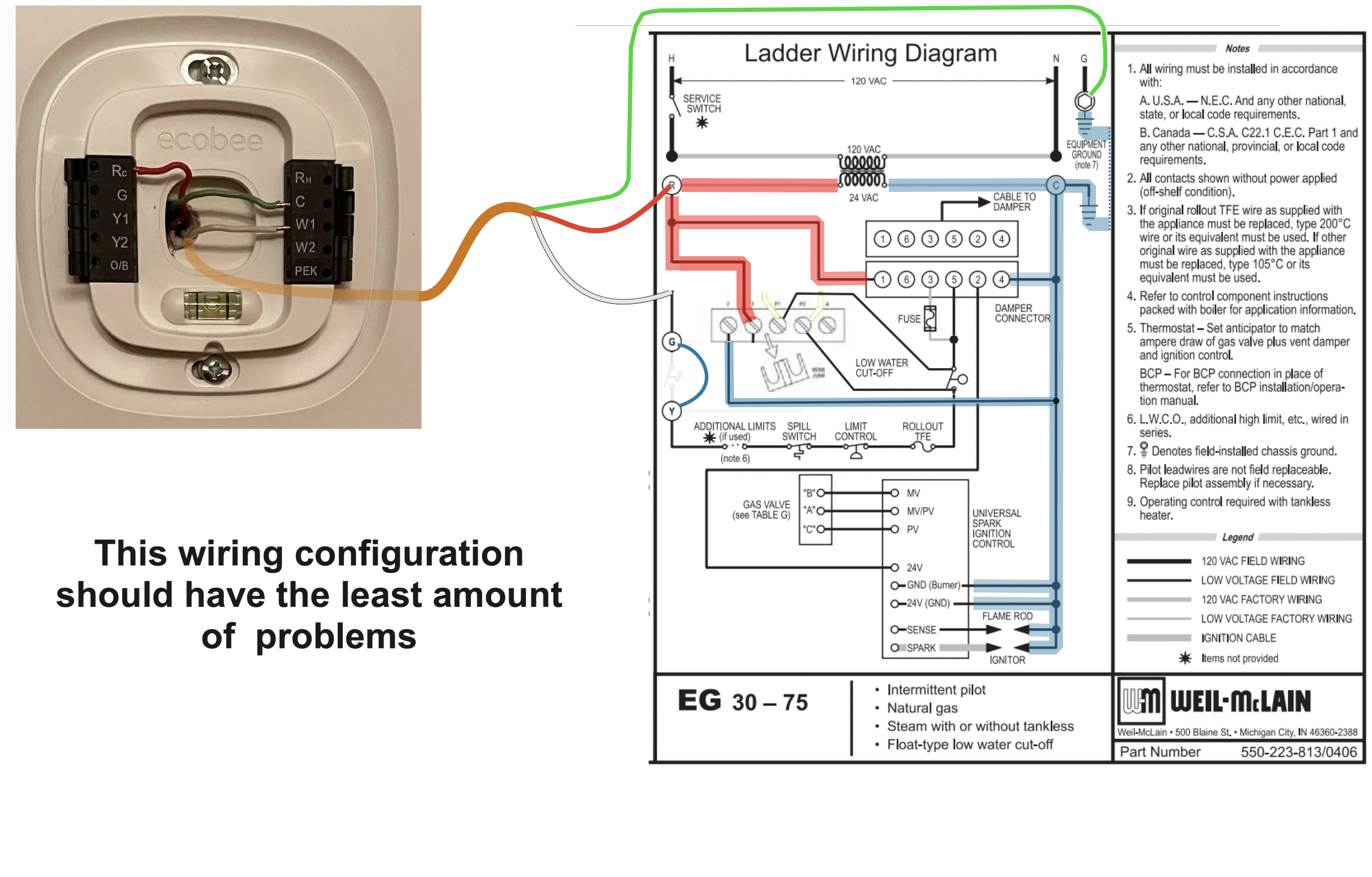
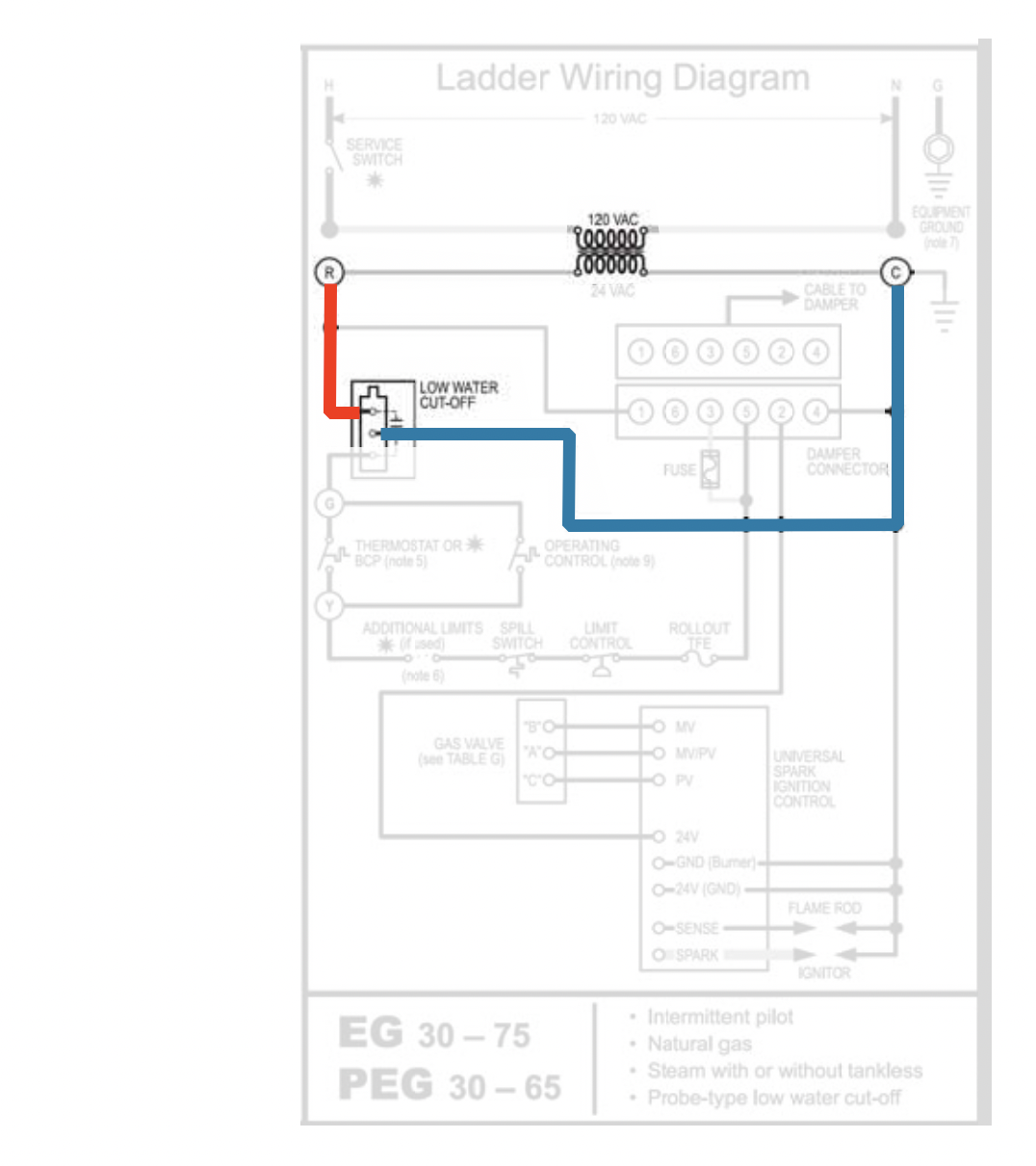
The ecobee thermostat may work just fine the way Mikey Pipes connected it, but since you are experiencing a problem, I might use an isolation relay or do the rewire where you remove the jumper on the LWCO between the 24v. R wire connection and the P1 position and reconnect the LWCO switch as instructed in the diagram. This is how the ladder diagram might look
Feel free to ask me any questions about this information.
I hope this resolves the problem you are having with your thermostat.
MOST IMPORTANT. MAKE SURE THAT ALL THE SAFETY DEVICES WILL SHUT OFF THE BURNER AFTER YOU COMPLETE ANY WIRING ON A BOILER'S SAFETY AND LIMIT CIRCUIT.
This can be done by removing one of the wires from each limit device like the Spill Switch, Roll Out fuse, Pressure limit switch, and or pushing the test button on the LWCO and observe the burner does no fire until the vent damper is completely open and the safety switch inside the damper motor indicates the damper is fully open.
Edward Young Retired
After you make that expensive repair and you still have the same problem, What will you check next?
0 -
Thanks for being patient with me. This is all new stuff for me. Although I love learning how this works, it can get complicated at times. Unfortunately, money is tight, so I have no choice! 😃
From what I can tell, in your first wiring diagram, you were trying to rearrange the wiring so the terminals do what they were "supposed" to do. ie. The R wire is connected to the R terminal (instead of the G) which supplies the power. And the W wire is connected to the G which is now connected to Y which is connected in series to the pressuretrol, damper, low water cutoff, etc. Am I right in my guess?
This is my current boiler setup:
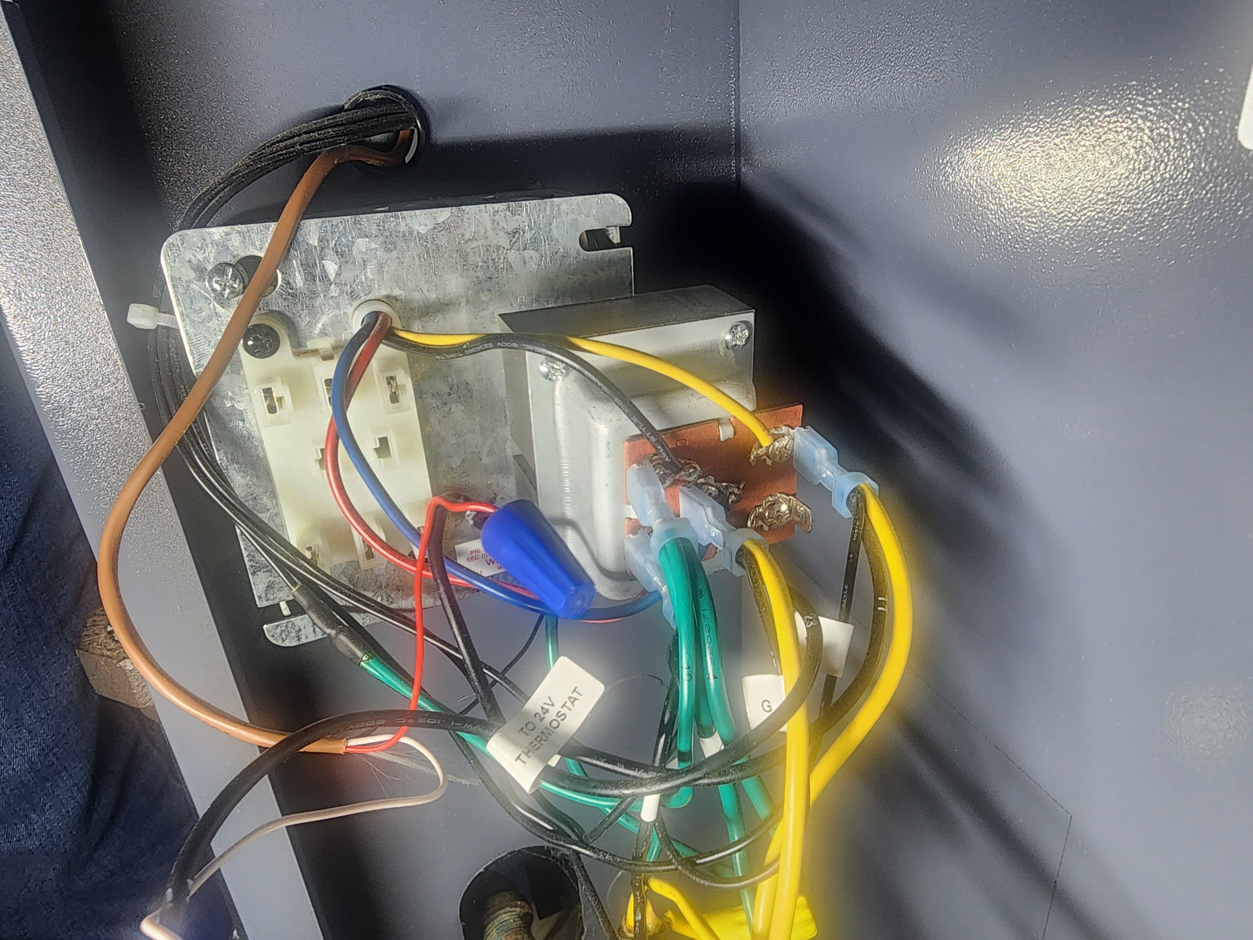
Currently, it looks like power is supplied to both the G and R terminal on the transformer. I'm guessing that the blue wire (connected to the G terminal) and the red wire (connected to the R terminal) from the emergency switch supplies power to both the G and R terminals, so both acts like the "R".
it looks like my Weil-McClain's low water cutoff is actually connected in series after the pressuretrol to the Y terminal. This is a 7-year old boiler and it came from the manufacturer this way.
I notice that on my boiler, the G terminal currently supplies the power to the thermostat. When temps are low, the tstat will connect r and w. W will trigger the Y terminal, which is connected to the pressuretrol, lower water cutoff, damper, etc., and at the end, it goes to the boiler controls. Since all of these are in series, if one of them is triggered, power to the boiler controls is terminated and the boiler turns off.
For my tstat, I don't know if the LWCO is the issue because the tstat reboots right away. It will immediately reboot once the tstat calls for heat.
Wi-Fi Disabled
I just noticed a big clue. When the Wi-Fi is disabled, everything works fine. When the Wi-Fi is enabled, the 1st ecobee reboots all the time. This made no sense to me because the Wi-Fi has nothing to do with the power dropping. Is it possible that the Wi-Fi is drawing more power. Since it's only 27V to begin with, perhaps when the heat is called, too much current is being drawn for a few seconds that it turns off the tstat?
I measured the voltage at the G (aka R wire) and C terminals. It's about 27V during idle, during the heat call, and after. It never dips, so the tstat should be getting enough power.
Is it possible that the multimeter is wrong? Is it possible that the multimeter averages out any fluctuations? Perhaps, the voltage drops for a second that the multimeter can't detect?
If so, how could I set up the connections to provide steady power?
Btw, I got off the phone with Ecobee a little earlier. They stated that it's impossible that the Wi-Fi would have an effect here. They didn't believe me. ¯\_(ツ)_/¯
They recommended that I replaced the wiring. I used the old, existing wiring to connect from the tstat to the boiler. They said that this could be the issue.
0 -
@MrVince replied: "From what I can tell, in your first wiring diagram, you were trying to rearrange the wiring so the terminals do what they were "supposed" to do. ie. The R wire is connected to the R terminal (instead of the G) which supplies the power. And the W wire is connected to the G which is now connected to Y which is connected in series to the pressuretrol, damper, low water cutoff, etc. Am I right in my guess?"
Lets take this one step at a time from the original WM wiring diagram with an electronic LWCO and an Auto Vent Damper. This may not be exactly what you have but it is very close to what you have. a different Brand of the LWCO may have slightly different terminal designations but all the terminals are the same. "only the names have been changed to protect the innocent"
Using the ladder diagram is simpler for followinf the basic electric circuit. (Basic electric Circuit includes the Source, the Control, the Load, and the Return Path back to the source)
This is what I mean:
The Source of the 24 volt electric supply is the transformer in the center of the ladder diagram. From the R terminal on the transformer to the #1 pin on the vent damper cable is the Source to the Load section of the circuit. Inside that vent damper is the switches and operators that are the Control for the damper motor. Also inside the Vent damper is the actual motor that is the LOAD for the circuit, Then the cable has a wire that is the Return Path to pin number 4 on the Molex plug that connects to the C on the transformer.
That is one complete circuit in the system. The next one is the circuit for the electronic portion of the LWCO. that needs to gave power all the time to operate the electronic portion that measures the electricity from the probe to determine if there is water at the probe or no water at the probe. That looks like this:
The Source, is the same and there are no controls that prevent this LWCO from operating in this circuit because we always need the protection of the LWCO to be ready to operate and shut down the burner if the probe detects a low water condition. So no controls means that load is always powered. The only real difference is the LOAD. The load is the processing unit inside the printed circuit board that consumes a very small amount of the 24 VAC from the transformer. You can also see the Return Path from the LWCO back to the transformer.
Now to look at your explanation above
The R wire is connected to the R terminal (instead of the G) which supplies the power (To the thermostat)
That is the first step in the process.
However you will need a return path to common for the thermostat C to the transformer So I added ir for you.
Now the thermostat's wifi and operating system is powered when ever the boiler transformer is powered, just like the LWCO and the Vent damper in the illustrations above. Are you still with me?
Now for the next part of your statement: " And the W wire is connected to the G which is now connected to Y which is connected in series to the pressuretrol, damper, low water cutoff, etc. Am I right in my guess?"
YES your are correct, but the order of the different limit controls and safety controls and operating controls that can shut off the burner is not important since they are all in series. That means that if any one of the switches opens, the the burner stops.
In this particular diagram it was easier to place W from the thermostat on to the C of the LWCO then the Normally Closed contact of the LWCO will be connected to the G on the boiler transformer. The Normal Open contact will then power the water feeder if you have one.
After the G on the boiler transformer the 24v. power goes thru all the other limit, operator, and safety switches it powers the #5 Pin on the damper to open the vent for exhaust. Once the damper motor opens completely the safety switch on the damper will power pin #2 that will allow the ignition control to light the burner.
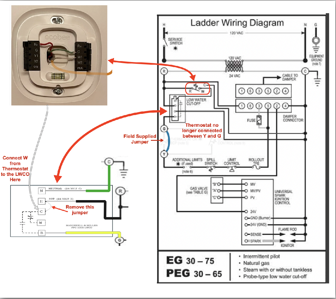
This is what the finishep produce should look like:
Edward Young Retired
After you make that expensive repair and you still have the same problem, What will you check next?
0 -
This Ladder Diagram will also work and it places the LWCO in the same place where my original diagram from 2024 connects the LWCO between the Rollout TFE fuse and the #5 pin on the vent damper connector.
Effectively the same diagram, but the LWCO is connected in series at a different location in the limit circuit.
Edward Young Retired
After you make that expensive repair and you still have the same problem, What will you check next?
1 -
Ed,
OMG! I didn't realize you responded. After we last talked, when you didn't respond that day, I pretty much took a break. With work, I was a bit burnt out from this mess. And I also thought you were through too. Today, I decided to come back and take a look at your previous suggestions. I was pleasantly surprised that you responded. Thanks!
Right now, I have kept my thermostat with the Wi-Fi off. The thermostat now works. When the Wi-Fi is on, the thermostat reboot a few minutes after the heat is called. My wild guess is the Wi-Fi draws a little bit of current all the time. As a result, when heat is called and the boiler's electrical components do their thing, this extra power demand from the Wi-Fi now pushes the total power demand over the edge so the thermostat shuts off.
Ecobee's technical supports strongly believes the problem is the old wiring that connects the thermostat to the boiler. They want me to replace that before anything else.
I figure it's going to take a few days to rewire the boiler as you suggested. I was going to wait until the spring (≈May) to do it. That way the boiler won't be down and my family won't be screaming for my head. Will be a good time to take a few days to rewire per your recommendations.
Can you do me a favor? Post your Venmo or something. I'll shoot you something for all your valuable help.
0 -
I'm not sure my situation even applies to yours but with my White Rodgers Series 90, I decided I wanted a remote temp. sensor inside for temp. averaging and that required that the thermostat be powered by 24VAC, which required a CycleGard swap to a 24VAC one (ridiculous that they don't have them able to support different voltages), which required the addition of an isolation relay that my boiler wired for 110VAC controls didn't require.
Might your problem be helped with an isolation relay?
1 -
Captain,
Thanks for the recommendation. I'll try the isolation relay if Ed's rewiring doesn't work. The only thing that makes me wonder if it might be something else is the fact that other people have used the setup that I'm using and it doesn't seem like they are having problems. Or maybe they are and they aren't complaining?
I am wondering if the boiler's wire harness is the issue. Ecobee's engineer recommended that I replace the older thermostat wiring inside the drywall, claiming it's too old. But it's thick copper lines. I can't see how thick gauge wires would deteriorate even after 50 years. On the other hand, although this is a relatively new boiler (7 years), early on, parts of the wire harness had to be replaced because the strand wiring inside was bad. I'm speculating (complete guess) that other parts of the wire harness is causing issues. Maybe, I should replace all of the wiring…
0 -
What is the existing thermostat wiring? What insulation, and what gauge?
Br. Jamie, osb
Building superintendent/caretaker, 7200 sq. ft. historic house museum with dependencies in New England0 -
Hey, Jamie!
Not sure but it's thicker than the 18 gauge that I bought to connect the wiring to the boiler. The thermostat wire went down the walls form the 1st floor to the basement. Once it got to the basement, I had to connect it to the wire I purchased because the old wiring went in the wrong direction.
0 -
Good. The 18 gauge (or rarely 16) — which often had a cloth wrap — has two possible problems: first, if it's really old it can actually get brittle and break, which is tiresome. The other is that the insulation can degrade and give shorts — sometimes pesky intermittent shorts.
However, if it's a decent gauge and otherwise seems intact, you aren't dealing with high voltage so that if you test it with a good miultimeter and it tests good for continuity and no shorts I don't see why it wouldn't be OK if it has enough conductors.
Br. Jamie, osb
Building superintendent/caretaker, 7200 sq. ft. historic house museum with dependencies in New England1 -
Yes, it had a cloth wrap. I guess it's 18 gauge although it seems thicker than the one I purchased. It doesn't seem brittle at all though. But like you said, there might be shorts due to the cloth deteriorating after 50 years. I guess I'll replace it.
0


Categories
- All Categories
- 87.7K THE MAIN WALL
- 3.3K A-C, Heat Pumps & Refrigeration
- 59 Biomass
- 430 Carbon Monoxide Awareness
- 129 Chimneys & Flues
- 2.2K Domestic Hot Water
- 5.9K Gas Heating
- 122 Geothermal
- 170 Indoor-Air Quality
- 3.8K Oil Heating
- 79 Pipe Deterioration
- 1.1K Plumbing
- 6.6K Radiant Heating
- 396 Solar
- 16K Strictly Steam
- 3.5K Thermostats and Controls
- 56 Water Quality
- 51 Industry Classes
- 51 Job Opportunities
- 17 Recall Announcements