Thermolic Mini Boiler BT3MBN circulating pump wiring

Hi All
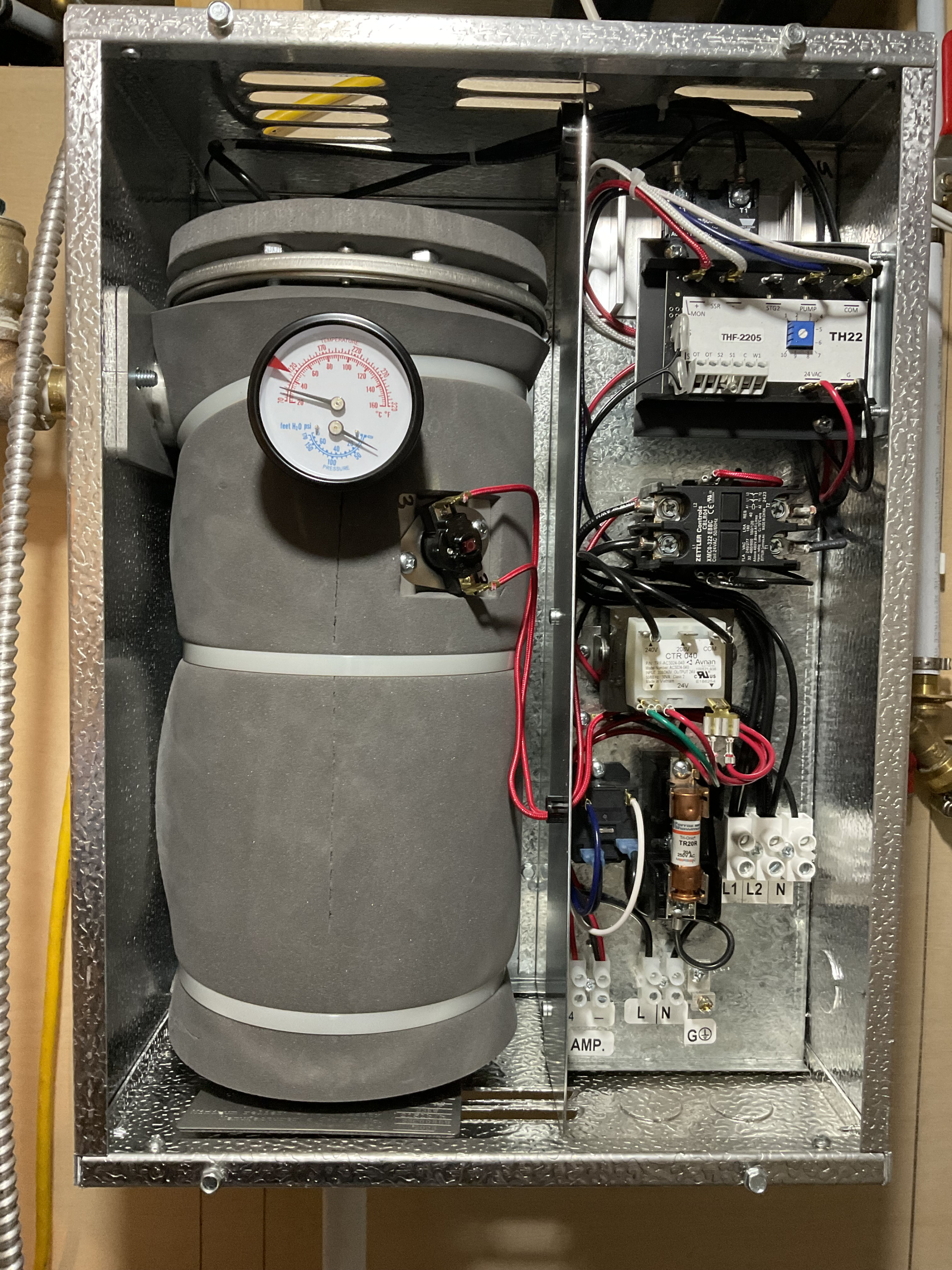
Would anyone know how I would wire a circulating pump to a Thermolic Mini Boiler BT3MBN? I have a 20 amp double pole breaker connected to L1 and L2. I have a 15 amp breaker connected to L1 and N. The thermostat is wired to the terminal block label 24 , C and W1 on the THF 2205 block on the top. I can’t figure out where the circulating pump gets connected to.
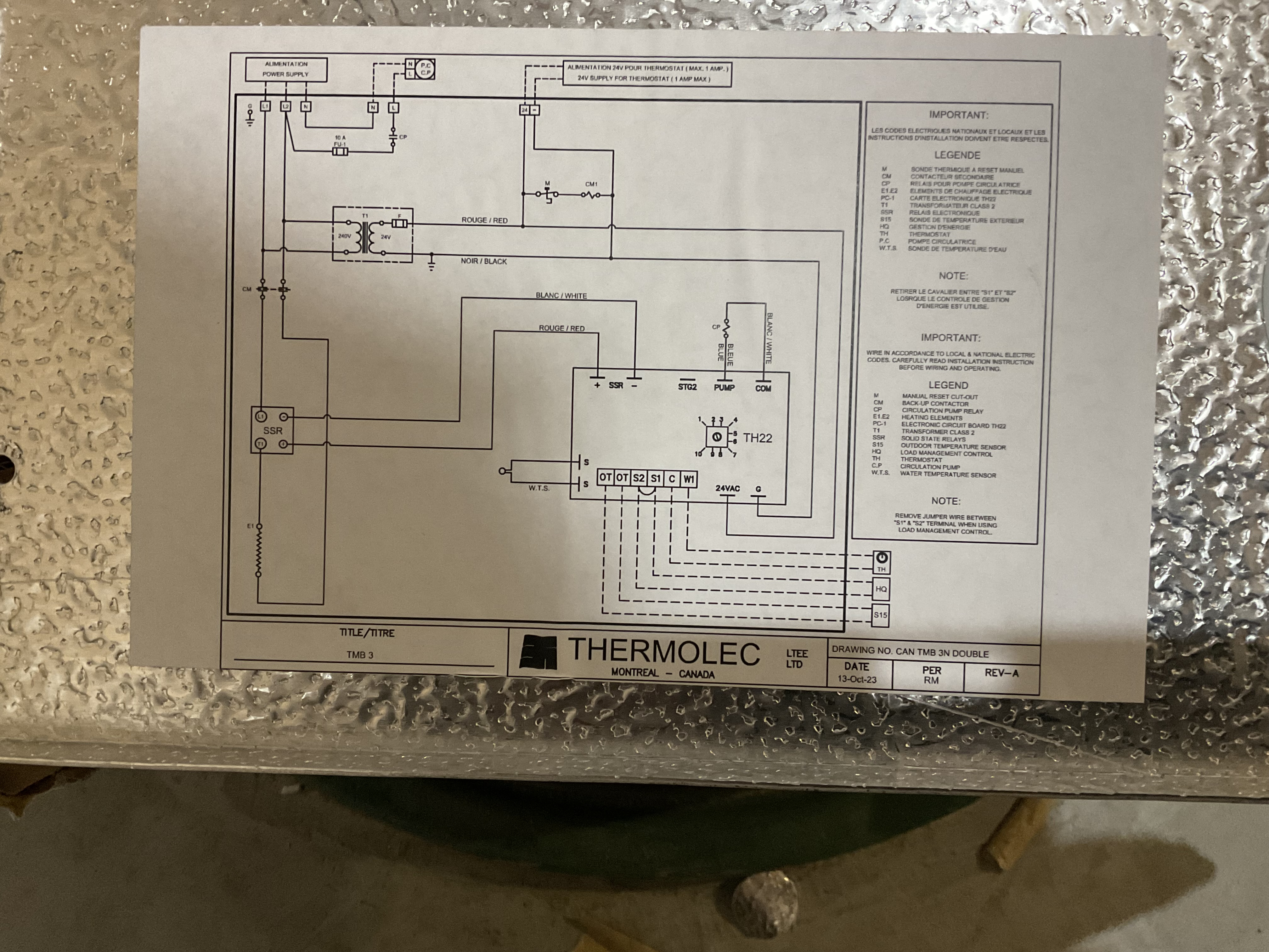
I’ve attached a picture of the boiler and the wiring schematic.
Any help would be greatly appreciated.
Bruce
Comments
-
On the TH22 control , pump and common terminals …
There was an error rendering this rich post.
0 -
Wait a minute. You wrote "I have a 20 amp double pole breaker connected to L1 and L2. I have a 15 amp breaker connected to L1 and N"
No. Please no. That wiring is not only not to code, but is horribly unsafe.
If nothing else, opening either breaker alone will not deenergize the wiring in the unit or the wiring from the panel to the unit. This is a fire hazard. It also could very easily kill someone trying to work on the wiring at the panel or at the unit or anywhere in between.
Before you do ANYTHING else, get rid of the 15 amp breaker completely. Disconnect and remove the wire from the 15 amp breaker to the L1 terminal. Check that the neutral wire from the panel has no breakers or switches on it and that it is properly connected to the neutral bus at the panel. Check and make sure the ground is properly connected on the boiler and to the ground bus on the panel.
Br. Jamie, osb
Building superintendent/caretaker, 7200 sq. ft. historic house museum with dependencies in New England0 -
SORRY! Typing mistake. The 15 amp breaker is connected to L, N & Ground. Not L1. It’s the bottom terminal.
20 amp to L1 & L2, no neutral.
0 -
THats Wrong!
Do not energize those breakers!
0 -
The 15 amp breaker is removed. How should it be wired?
0 -
You don't need it at all. You DO need the neutral associated with the 20 amp double breaker circuit connected to the N terminal where it says "L1 L2 N" on the terminal block on the far right side of the cabinet, a few inches up from the bottom.
That will provide power to the L and N terminals in the two terminal block near the bottom. Those two terminals are the power output for your circulating pump, and power to that pump is controlled by a relay in the control panel.
Which is, I think, the answer to your question — how to wire the circulating pump to the boiler.
It is, by the way, very likely that the internal 10 amp fuse in the pump power circuit has blown, so you will need to replace it..,
Br. Jamie, osb
Building superintendent/caretaker, 7200 sq. ft. historic house museum with dependencies in New England0 -
Hi Jamie,
Yes that explains it and answers my question. I should have posted my questions earlier.
From the picture I posted, are you able to point out where the 10 amp fuse is located?Thanks
Bruce.
0 -
At a first pass, I'm going to go for the cartridge fuse labelled "TR20R" just above the N teminal of the two power output terminals. That's a bit of a guess, however, as the circuit diagram shows the fuse on the L side…
Br. Jamie, osb
Building superintendent/caretaker, 7200 sq. ft. historic house museum with dependencies in New England0


Categories
- All Categories
- 87.6K THE MAIN WALL
- 3.3K A-C, Heat Pumps & Refrigeration
- 59 Biomass
- 429 Carbon Monoxide Awareness
- 124 Chimneys & Flues
- 2.2K Domestic Hot Water
- 5.9K Gas Heating
- 119 Geothermal
- 168 Indoor-Air Quality
- 3.8K Oil Heating
- 78 Pipe Deterioration
- 1K Plumbing
- 6.6K Radiant Heating
- 394 Solar
- 16K Strictly Steam
- 3.5K Thermostats and Controls
- 56 Water Quality
- 51 Industry Classes
- 50 Job Opportunities
- 18 Recall Announcements