Air purging with poorly placed coin vents

Hi all,
I'm about to take my second stab at purging the air from my boiler. I did it once last season and I remember struggling on one section that had several poorly placed coin vents (not at highest points in heating loop) on a baseboard loop. The technique I used to purge the air from this section was to effectively drain the water in the loop from one of the coin vents to remove some of the air pockets that were causing the blockage. It was difficult in that the coin vent was in a really tight space and I would get water everywhere since the vent was located above me. Can I attach an air hose line to a 1/8" npt coin vent and if so, what size would this even be or can I swap out the coin vent for a 1/8" valve type fitting that a hose can be attached to? I haven't seen any products like this.
I was originally planning on installing a purge and fill valve, but I have run out of time (cold out) and I don't want to risk messing up some bigger solder joints and having to find somewhere that stocks 1 1/4" copper pipe.
Comments
-
Baseboard should have a purge valve on the line by the boiler . Was the baseboard added to the system from original ?
There was an error rendering this rich post.
0 -
If you have the room, you can do something like this.
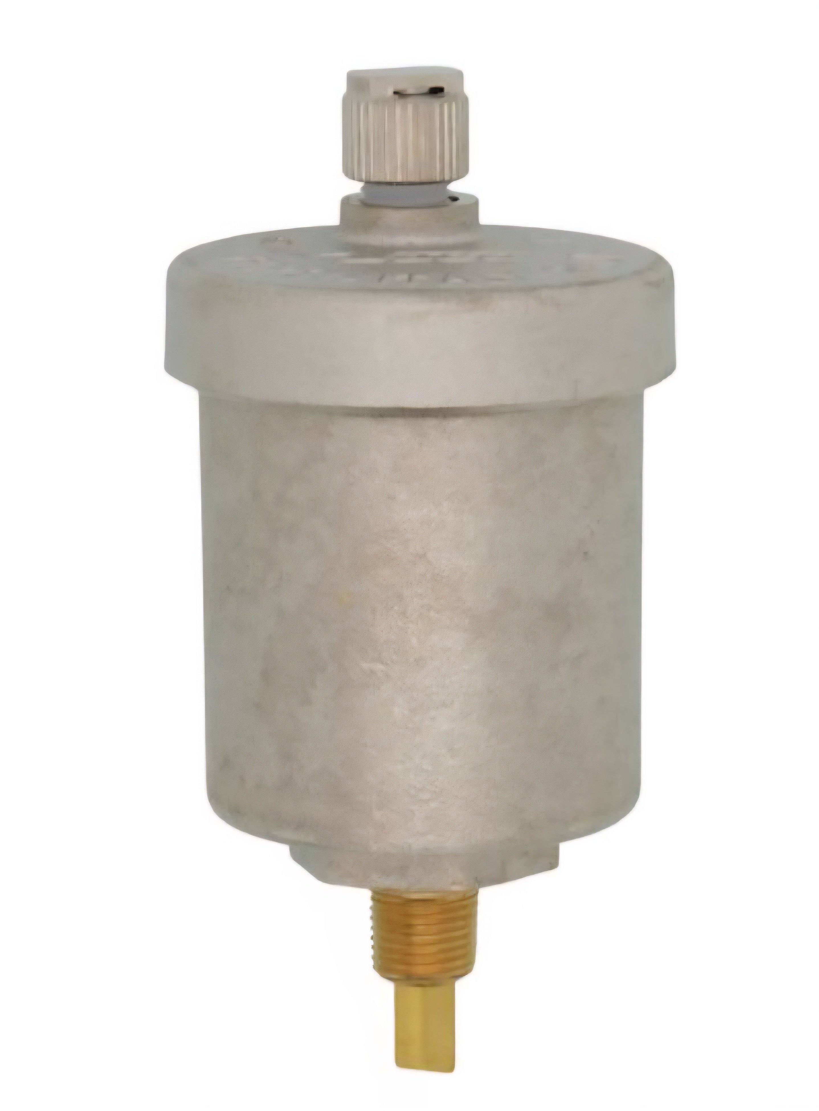
Just close the valve when done. Or leave one open to always eliminate air.
0 -
@Big Ed_4 This is a converted gravity-fed system (100 year old house). The boiler services several cast iron loops in parallel. This is the only loop that is base board and it is servicing three baseboard radiators that are piped in series. The pipping on this loop goes up and down between floors, so it's challenging to purge. There is a coin vent located on the three baseboard radiators, but they get even more water everywhere, so I believe that's why I purged from the basement for this loop.
0 -
@HVACNUT is that a 1/8" npt valve? I didn't think that existed, but I also didn't look that long. Can you draw out what you're suggesting? I'm trying to understand how you're suggesting to replace an existing coin vent with a valve and an auto air vent. What fittings would you use and how would you drain (npt → ght?)?
0 -
That section on baseboard sounds all wrong . It should be on its own zone . Would it be fair to say it does not work well when its bleed ?
There was an error rendering this rich post.
 1
1 -
@Big Ed_4 You're 100% correct. The plumbing on this system is a hack job and I try to do my best with it before I rip it all out. It should not be plumbed with the cast iron rads, but it was. I suspect it was done some time before zones were well adopted. There are no zones on this boiler system. The air separator isn't even located in the correct spot. The balance is way off on the baseboard rads (scalding hot). An idea I had before adding zone heating was to add a trv valve to the start of the loop to balance the baseboard heat output. I currently have no ability to control the flow through the baseboard rads, so I am slightly worried with some of the changes I made this offseason (more trvs on cast iron rads that previously had no flow control) that they'll be even hotter this season. The reason I haven't completely repiped everything is because it's a massive job. Massive 100 year old cast iron piping all throughout the basement. I plan to address it, I just need a free summer…
0 -
Radiators run temperatures 120* -160* ,tube and fin run temperatures 160*-200* . I don't see an easy fix …
I would recommend zoning that section and upgrade from baseboard to panel Radiators . Size them for each room using 160* as your guide on the chart .
From here I don't see an easy fix and see a re-do .
The person that paid for the install was looking for the easy fix , like a flipper maybe ..
There was an error rendering this rich post.
0 -
you don't have to replumb everything, you just need to pipe the baseboard loop back to the boiler and control it with a second circulator or put in 2 zone valves.
0 -
@mattmia2 @Big Ed_4 I understand this is the ideal solution and I already have that planned. The issue right now is that it's getting cold out and I'm looking for an easier way to purge air out of the system that doesn't require me putting the boiler down for several days. I was thinking of doing something clever with one of the coin vents and I actually think @HVACNUT had a good idea. I could put a 1/8" npt valve (if it exists) in line with a hyvent. This would allow me to hot swap the hyvent with a ght / hose line adapter if the system has air in it. I also could just keep the coin vent if a 1/8" npt exists.
0 -
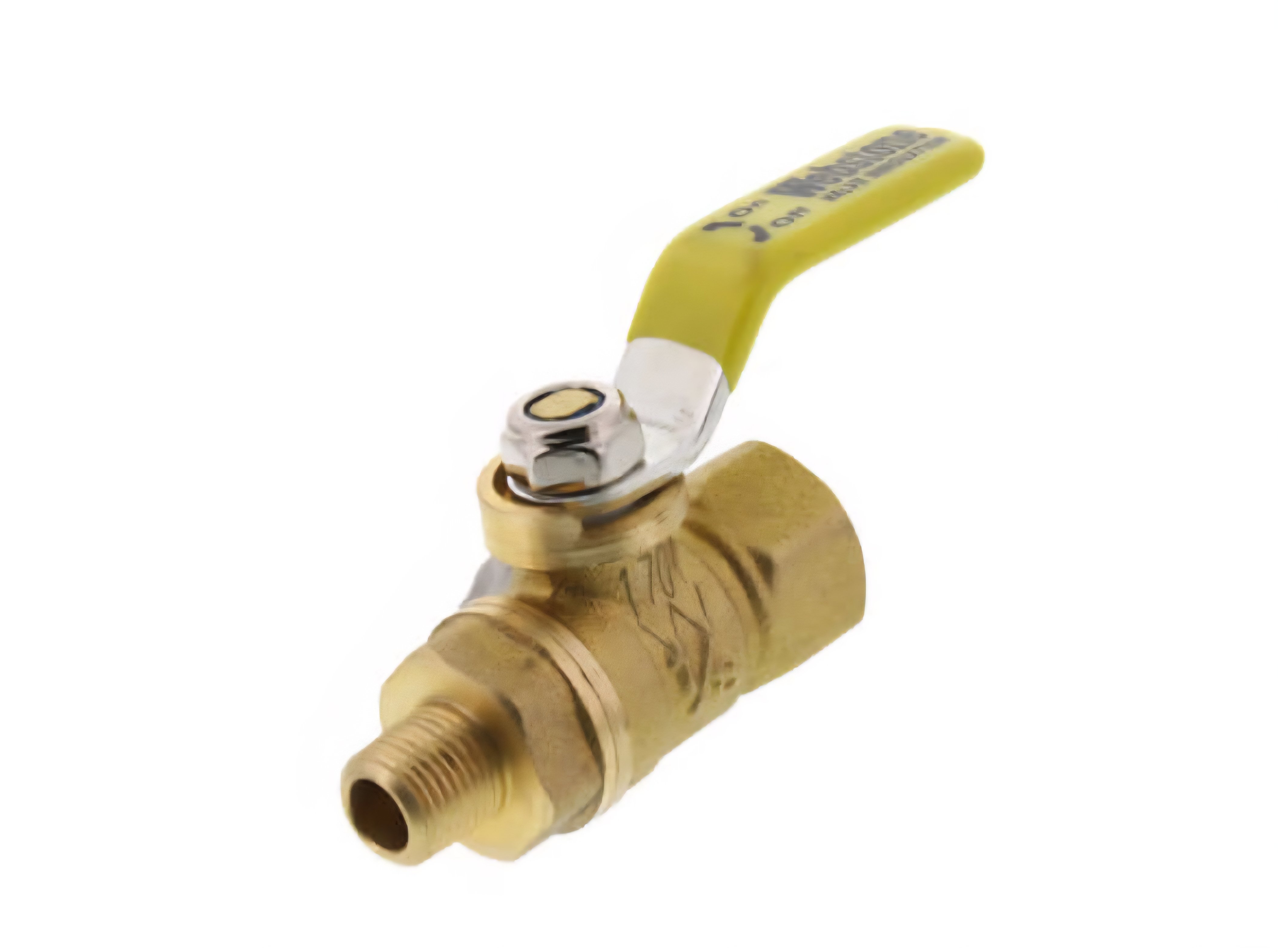
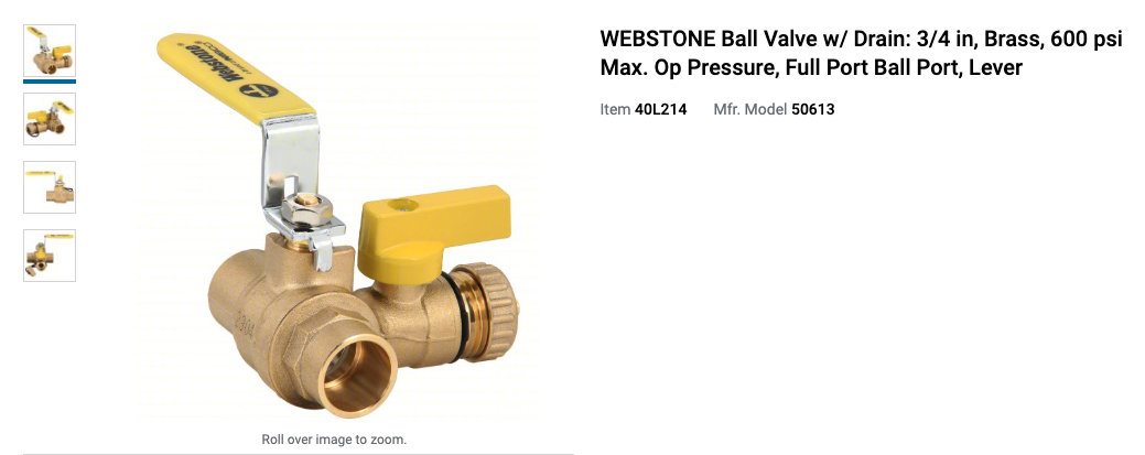
you could put something like this in the baseboard loop.
https://www.supplyhouse.com/Webstone-50613-3-4-Sweat-PRO-PAL-Full-Port-Ball-Valve-w-Drain
 1
1 -
Can’t get links to work or add photo, getting error message.
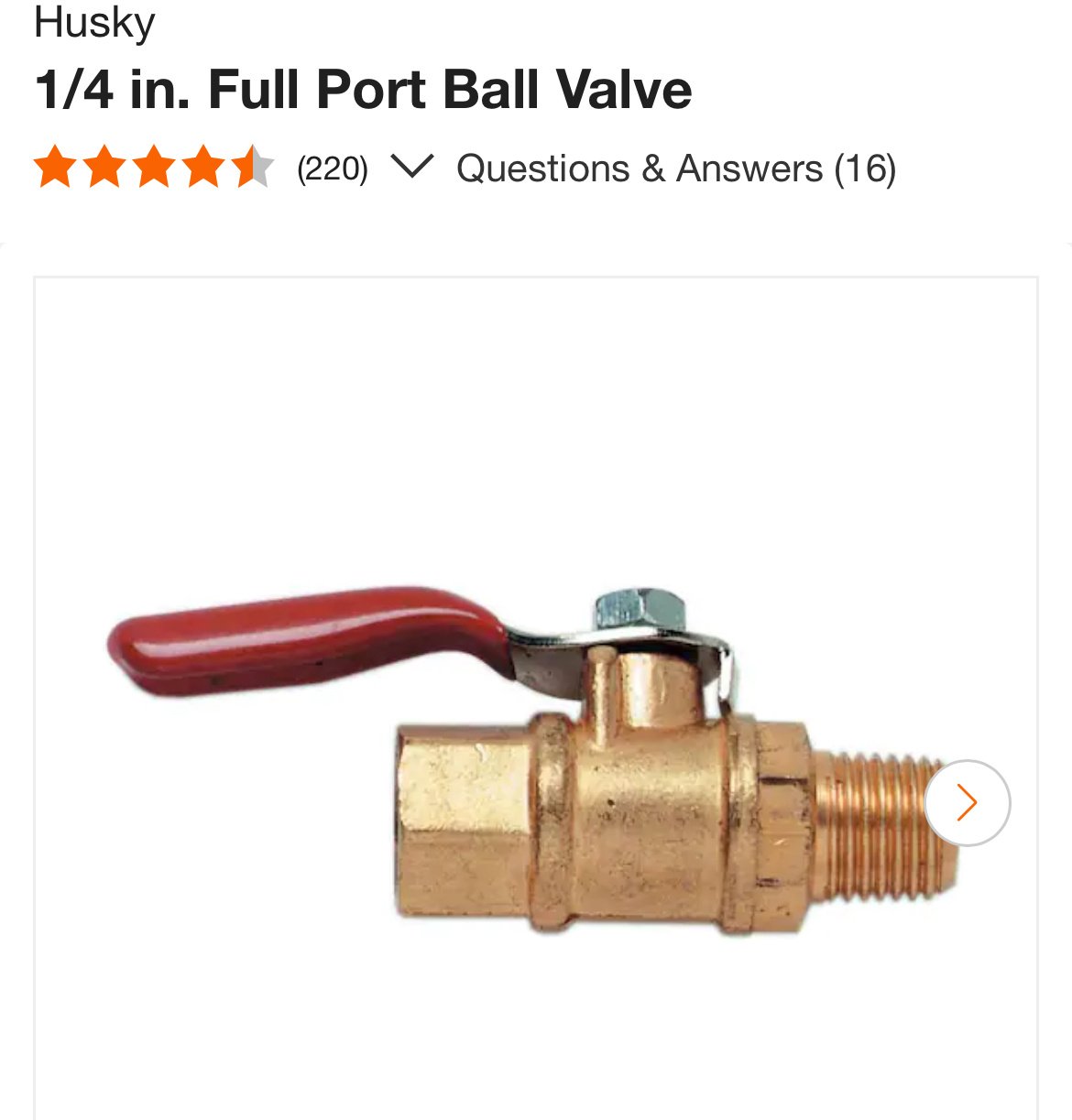
Trying to post a mini ball valve 1/8” from zoro.
0 -
sometimes called gauge cocks 1/8 and 1/4
Most valve manufacturers offer them
Or Home Depot
 Bob "hot rod" Rohr
trainer for Caleffi NA
Living the hydronic dream0 -
Bring up the system pressure while bleeding and lifting up the element on the bleeder end may help you out in the mean time …
There was an error rendering this rich post.
0 -
I ordered the 1/8" valve from supply house with an npt to barb adapter. I'll hook up pvc vinyl tubing to the adapter and when I feel I've purged the air from the baseboards, I'll swap out the adapter for either a plug or a coin vent. I think this will definitely help me purge air from this loop without getting water everywhere. The valve is hidden in a laundry room, so it won't be an eye sore on top of a radiator anyway.
0 -
You don't drain it. The air will vent out during the heat cycles.
0 -
@HVACNUT The location of this coin vent is not at a high spot in the loop. It's actually probably at one of the lower spots in the loop. I have no idea why anyone would put a coin vent here. I can't image an auto vent would do much either since the air can get trapped above this location and a cycle might get into an air lock in this loop. I didn't think an auto air vent that isn't placed at the highest point in the loop would help with an air lock in the loop when the vent is placed after and lower than the air lock is located. In this loop, there were several spots where there were air locks last year. Last time, I drained each baseboard in series till I was finally able to get flow. The approach I want to try now is to just drain from the end of the loop till I'm only getting water. I'm really looking to use this to help clear out air locks from this loop. Only to be used during initial purging to clear out air locks from the loop. Maybe I'm completely wrong in my logic, I'm just remembering what I had to do last year.
@HVACNUT What would be the point of the npt valve that you linked or were you just sending me a link for a 1/8" npt valve?
0 -
the "vent" could be at a low spot to allow the system to drain.
even someone with mediocre soldering skills could sweat in a purge station in a couple hours so that you could purge most of the air out. or you could do it with compression fittings.
0 -
@mattmia2 I've soldered a bunch already, but I'm less comfortable trying my hand at 1 1/4" soldering and trying to find copper piping for 1 1/4". I'd basically have to use a sawzall and then debur and sand. It's just something I haven't done before and it's getting pretty cold without heat. I already ordered everything I need to solder in the purge station, I'm just not feeling confident about sweating in on 1 1/4". I could try. I've definitely soldered in more gnarly spots than behind the boiler. I'm more worried about finding places that stock 1 1/4" pipe if I mess up.
0 -
a couple of the real hardware stores by me will sell you cut pieces of 1.25" pipe. I would do it with npt adapters and a coupler, the mass of an adapter is a lot less and it is a lot easier to sweat than the body of a 1.25" valve and if you screw it up sufficiently you haven't ruined a $75 valve. Looks like the big box stores have 1.25" pipe although a 10' piece is a bit of an investment.
0 -
@mattmia2 yea, that was pretty much how I was planning on doing it. I bought a 1.25" dielectric union (which I don't think I needed — could've used a standard union), two brass nipples and a 1.25" purge and fill valve and a 1.25" C to NPT fitting. My circulator is on the return side, so I was going to plumb in the purge and fill before the circulator on the return. I was going to go circulator pump → copper pipe → union (sweat) → nipple → purge and fill → nipple → C to NPT fitting. I would start by sweating in the adapter fitting and the sweat side of the union then wrench the rest so I know I won't melt anything. Like I said, this is a 30 year old boiler and I feel like the issue is more so finding parts if I mess up (e.g. can I damage the circulator pump if I solder too closely).
0 -
If it is a cast iron boiler, other than the heat exchanger and cabinet parts(and sometimes controls on a few models with integrated controls), the parts are standardized and an equivalent replacement is not hard to find. The boiler trim is all standardized.
Are you putting this purge station where it will force flow through only one baseboard loop? If the flow is divided between more than one loop you may not be able to get enough flow out of just a PRV or hose attached to the system to pull the air out.
0 -
@mattmia2 There's no zones in my system and since all of my rads / loops are plumbed in parallel, the purge and fill would be at the end of the circuit, so I could hopefully push all of the air out of the port side of the purge and fill while I pressurize the system. The original approach I described above was a pseudo purge station on the baseboard loop so that I could guarantee that I could purge from the trouble spot. I was not sure how well the purge and fill would work, but I assumed it should work since it's at the end of the circuit.
0 -
You would want an isolation valve on each loop too so that you can close off the other loops and purge them individually. Presumably there are already balancing valves that could be used for this.
0 -
@mattmia2 The only valve I could use to isolate anything would be the newer TRVs I installed, but I can only close the feed side of the second floor rads using the new TRVs. They don't have balancing valves that I can close on the return side of the rads. The older 1st floor rads still have 100 year old valves on them. If I can't isolate the rads, is a purge and fill useless? I thought purging with a purge and fill station in my head would be akin to when you drain your regular domestic system and refill, the pressure of the water pushes the air out of the open faucets. In this case, the purge and fill would be your "open faucet".
0 -
you need enough flow to pull the air down with with water and out whatever drain you are using. It is hard to get that much flow in multiple loops simultaneously without something like a pump cart. Are the TRVs in a series loop or are there parallel mains on those parts of the system? You cold also just put the purge station on the part of the system you can't get flow started in by bleeding.
0 -
Every loop is in parallel, so the TRVs are each in their own parallel loop. The feeds and returns for every loop can't be isolated. Every loop branches from some very large pipes off the boiler. I have no way to tie into these pipes without removing 100 years of piping and then installing valves. I was able to break some of these fittings loose last year, but I would rather not do that ever again. It's very hard work imo. I'd rather just remove the pipes and update to all copper and a more efficient boiler. For now I'm trying to just hobble by, that's why I thought I could potentially install a pseudo purge station on the baseboard heaters. I could also do an auto vent like you originally suggested, but I wasn't sure if that would actually purge the air like a dedicated drain would.
The more I think about it though, a dedicated drain would also pull water from the return side after the baseboards, so there's actually no guarantee I can purge the air from this section without a purge and fill style valve to prevent pulling water from the return side. I could sweat a 1/2" copper valve on the return side of this loop and close it and then purge the loop from the 1/8" valve I described originally.
0 -
if you're going to sweat a fitting in to the 1/2" i would make it a purge station so you can block flow and route it out through a hose.
If the CI radiators are indeed in a series loop, a TRV or any working radiator valve will block the flow and allow you to force flow through only the other loop.
0 -
Sorry, the CI radiators are all plumbed in parallel. So the TRVs are all in parallel. Closing one TRV only stops the flow to one of the rads since they're in parallel. The baseboard rads are plumbed in series.
0 -
Can't I create a pseudo purge and fill with two valves, where one of the valves has a drain? Purge and fill valves are expensive and aren't stocked at big box stores.
0 -
sure. the purge station just makes it so you don't have to assemble a bunch of fittings and valves together. The purge station has a 3 way valve which simplifies things though you could use a 3 way valve and boiler drain or a 2 way valve a boiler drain and tee.
0 -
After reading some of the older posts about this system, it is clear to me that @garfungle may not have a clear understanding of how the system is piped, or how to remove air from the system.
So I can be clear, Is this the same system that you wanted to put remote control radiator valves (you called TRVs) on each radiator in 2024? If it is, I believe that we have determined that you own a direct return gravity heat system that was originally heated by a hand fired coal boiler.
If that is the same system, then the baseboard radiators that were added at some later date from the original radiator system should not be connected to this system.
If you really want to get all the air out of the baseboard radiators that are connected in series to the system, you need to disconnect the baseboard series loop from the system and perhaps use oxygen barrier PEX tubing to pipe that series loop to make a home run the the boiler room. Then add a separate zone using a separate circulator pump different from the existing circulator that is now operated by the modern boiler that replaced the coal or hand fired boiler from times past.
I wish to know this information before I suggest any further ideas to solve the problems you are having.
Edward Young Retired
After you make that expensive repair and you still have the same problem, What will you check next?
0 -
When you want to remove air from a gravity hot water boiler system you need to add enough water pressure to the boiler in order to lift the water higher than the highest radiator. This is called static pressure. In a 2story home that might be about 12 PSI in the basement to get about 2 PSI at the top radiator to force the air out.
The typical way to remove the air from the radiators in this system is called VENTing. We actually called it Fill and Vent the System. We needed to do that when a replacement boiler was installed.
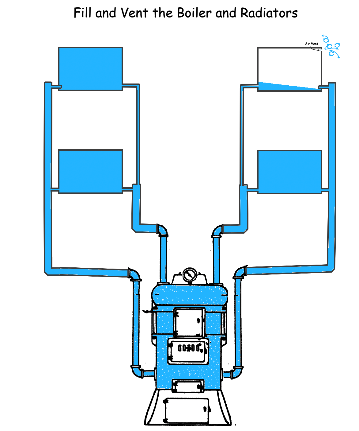
You VENT the radiators individually by opening the loose key air VENT on each radiator to let the air out until water comes out. That way you know that the radiator is full of water. You then make sure the water pressure at the boiler is at 12 PSI and continue to the next radiator air VENT and repeat the process first floor first then the second floor and so on, until all the radiators are full of water. No Air Left in the radiators.
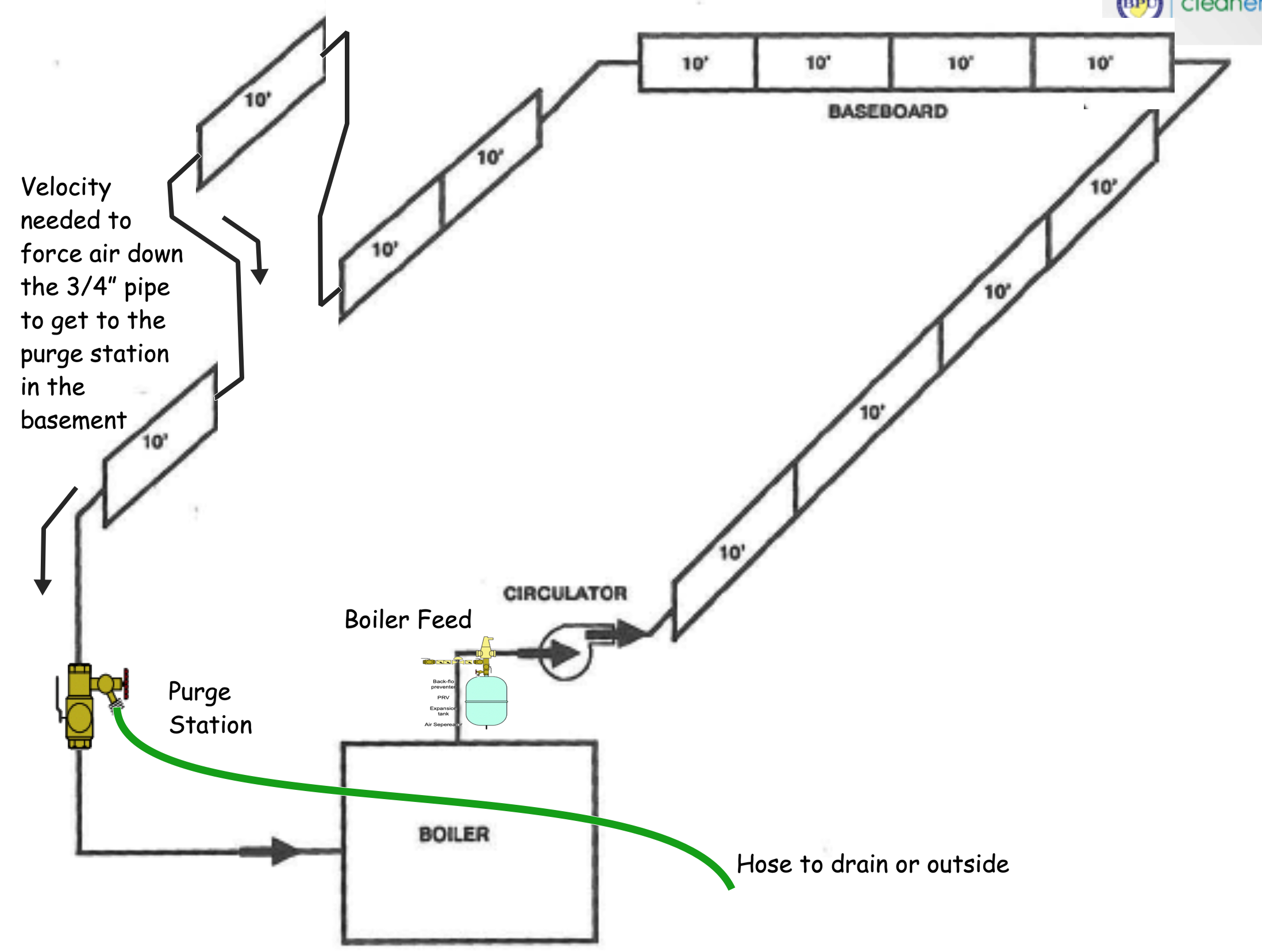
When you have a series loop of baseboard you can not depend on this venting method to get all the air out because the nature of a series loop means that sometimes the baseboard pipe and the connecting pipe will drop down below the floor and rise above the floor at another radiator several times in the loop. As a result the air pockets in the center sections of the baseboard loop will not have a way to allow the air to vent at one end or the other. That air will be trapped and that entire radiator loop will not heat. The typical way to remove air from that series loop is to purge the air from the loop. This is usually done in the boiler room where each series loop zone will have a purge station or be connected to a central purge station.
To purge the air from a series loop you increase the pressure in the system to a pressure that will force any air in the pipe to be entrained in the water flow that will force the water through any vertical pipe where the water needs to flow down to the basement. Thai defies gravity since the air is lighter so the force of the water must be great enough to take the air along with it as it flows to the purge station in the basement.
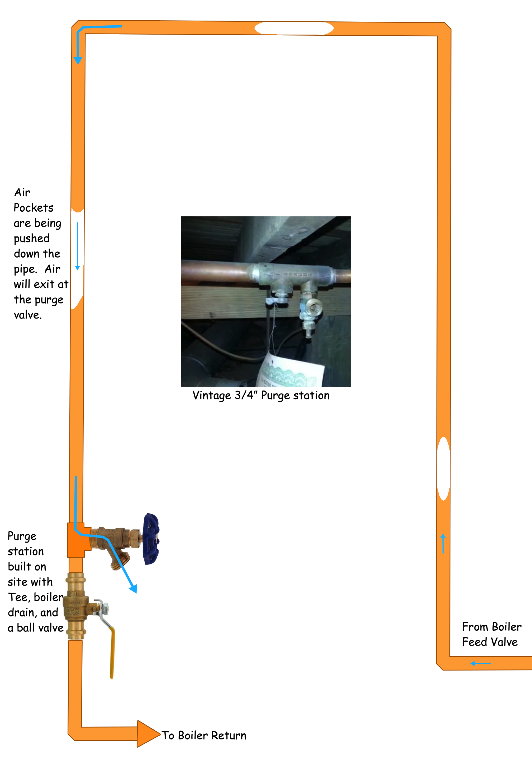
This rapid flow will ensure that all the small vertical pipes between each radiator will not collect enough air to stop the flow of heated water through the radiators. If you design the piping system properly with the proper air elimination devices strategically located, you can actually design an air free system that will purge any small amounts of air as the system operates.
Edward Young Retired
After you make that expensive repair and you still have the same problem, What will you check next?
0 -
@EdTheHeaterMan This is the same heating system and this is exactly how I was planning on purging the system. I'm not sure why you think I don't know how my system is piped. I've spent a while on this system and have filled / drained it, balanced and purged it several times already. I'm just reiterating what I've already had to do with this system. I'm trying to make the act of purging air from the series plumbed baseboard heating easier and not a process of popping up a ton of water that comes out of the coin vents on the baseboard rads. I have no zones and no isolation valves because this was all plumbed before I ever bought the house, so I'm trying my best to work with a hacky heating system. My aim to begin all of this was to purge the air more easily from the baseboard section which is plumbed in series. I believe that by introducing a shut off valve to close this loop, it is effectively acting as an isolation valve. I can then install a drain before this shut off in the loop to purge air as you described. I'm trying to find the easiest way to do this on a system that is a nightmare to work on, but the history of the system is correct. I have no intention to fix that incorrect installation until it's warmer out — I need to work with what is here.
0 -
A valve like this at the end of a series fin tube loop should be all you need. Or build one with a tee, hose bib and ball valve.
The cost of these and simplicity of just two connections make it an easy decision. Threaded sweat or press versions available.
The parallel rads will be harder to purge. A pump cart with 12- 15 gpm flow rate will generally blast enough flow to push enough air to get the circulator and air purger finishing it off.
A plastic garbage can and a cheap plastic pool pump is an inexpensive way to build a high flow pump cart. Mount the pump on top of the can with a piece of plywood, use the largest hose you can get to connect into the system.
That clear vinyl hose from Home Depot works fine for a hose, get 1" and adapt into the system somewhere.
Bob "hot rod" Rohr
trainer for Caleffi NA
Living the hydronic dream0 -
In the event the Hy- Vent leaks or fails, no need to drop the pressure on the boiler to replace it. Just shut off the valve.
0 -
I'm not sure why you think I don't know how my system is piped.
I misspoke, I meant that you may not completely understand how the incompetent previous plumber or DIY piping will not work properly under any circumstances. The heat emitters function on two completely different principals and at different temperatures. Your boiler is not set up for two temperature operations or to provide two gallons per minute flow rates for each type of heat emitter.
No one here expects you to understand it completely since you have only been experiencing this for the few short years you have lived here. Many of the professionals here have been doing this for many years and have experienced this problem many times. I meant no disrespect.
As far as my previous comment, I have added the illustrations with the different air removal methods in detail in order to make the concept of purging and venting more clear.
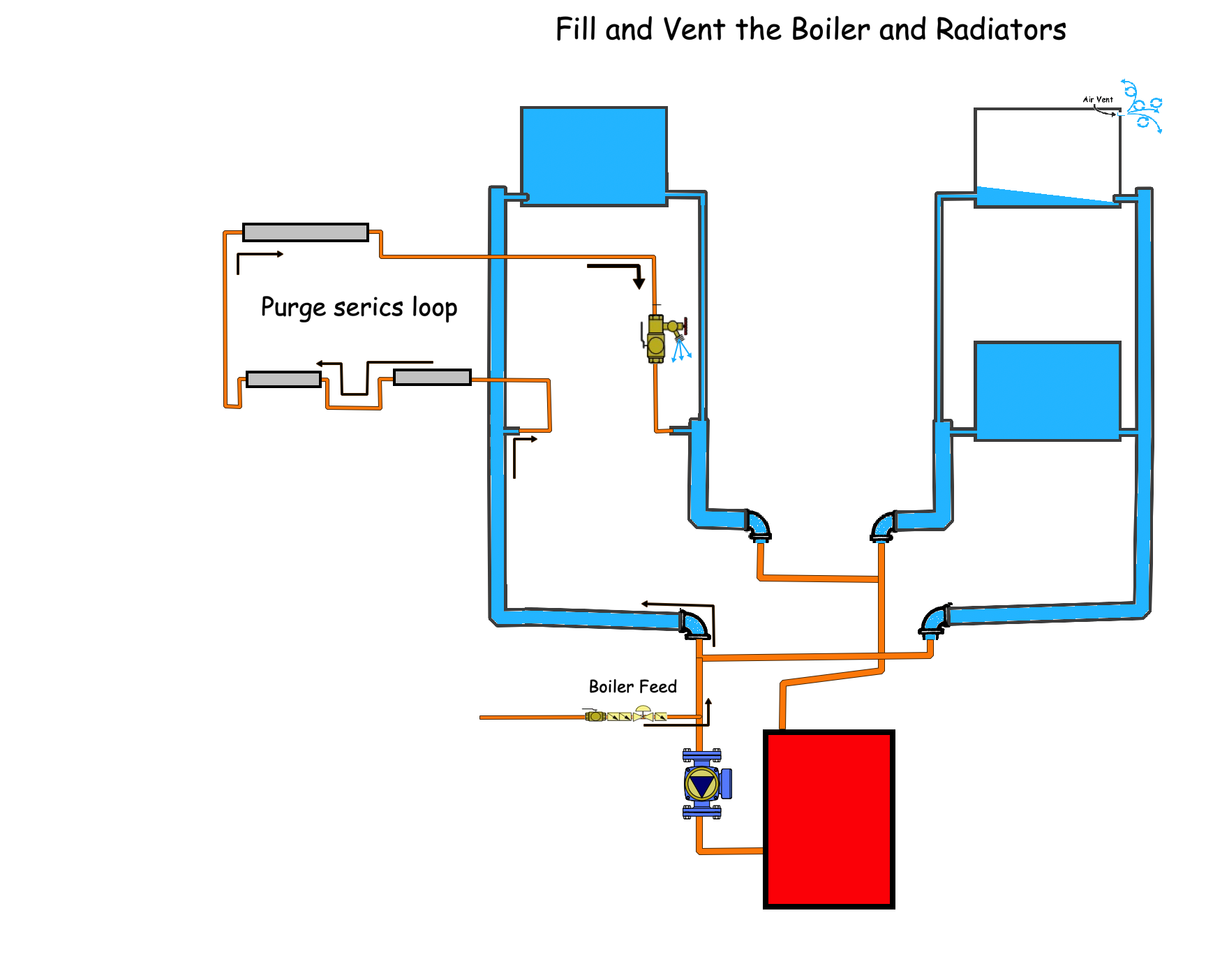
For your system, you can add a ball valve on the end of the loop that is opposite of the side where the fill valve is located. For example if your fill valve for adding water to the boiler system is located on the supply side, then place the purge station on the return side. If your boiler fill valve is located on the return side of the system, then place the purge station on the supply side and force the air out in reverse direction. Either way will work.
This is only a guess at what you may have from my experience of 40+ years in the trade. This is typical of the mistakes that others have made, that i have come across in my many years.
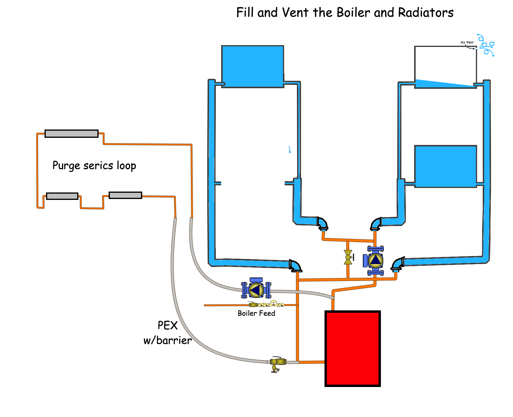
This would be the proper piping for two temperatures and two flow rates. the near boiler piping has been rearranged to create a bypass for the lower temperature radiators and the hither temperature radiators are piped without a bypass to get higher temperature water at a faster flow rate (no bypass)
PEX tubing with Oxygen barrier will be easier to get from the boiler room to the radiator location.
Edward Young Retired
After you make that expensive repair and you still have the same problem, What will you check next?
0 -
@EdTheHeaterMan from your diagram, if I have a valve at the end of the in series baseboard loop that has a drain and it's on a circuit with a bunch of CI rads that are vented. What would be the best way to purge the air? If I start by purging the air from the top level CI and work my way down and then purge the air from the baseboards, there still might be a section of piping that has air trapped in it. How will air travel between the two modes of purging? E.g. if I install a shut off valve at the end of the in series baseboard loop and I close that valve, what will happen to air that is outside of that loop at the end of the loop after the valve? Will it seek to travel up because it is less dense than water or will it be trapped by the hydrostatic pressure of the water from the returns of all the other CI rad loops?
0 -
First of all, is my guess at how the baseboard was added a close approximation of your system?
next. Always vent all the CI rads from the bottom floor, then the second floor, then the top floor last. Be sure you have all the air out of the mains and the radiators this way. Bottom first to top last. You will need the boiler pressure to be high enough to vent all the radiators on the top floor.
Finally, to vent the baseboard loop you must have a valve to shut off one side of the series loop. Then you need a drain valve that opens to a garden hose to direct the air and water out of the system. That is called purging. If you only have the bapp valve and no purge or drain valve that can be opened, then that valve must be added.
If you are going to the trouble of draining the system to add a valve, you can decide if it is worth the trouble to correct all the problems or just stick with the quick fix. The quick fix will not get you completely where you need to be, but you can get all the air out.
Edward Young Retired
After you make that expensive repair and you still have the same problem, What will you check next?
0 -
what will happen to air that is outside of that loop at the end of the loop after the valve? Will it seek to travel up because it is less dense than water or will it be trapped by the hydrostatic pressure of the water from the returns of all the other CI rad loops?
Air will find it's way to the top of the container. Always! if there is a loop that goes up then back down, the air will form a pocket at the top of the loop.
Eventually air will dissolve into the water and be released from that water based on temperature and pressure This is called Boyle’s Law of dissolved gasses. Understanding Boyle's law can help you design a system with air problems or design a system that has no air problems. I like to think of Boyle’s Law as the opposite of Relative Humidity. You already know that the air you breathe has water vapor suspended in it. We call the amount of water vapor in the air Relative Humidity. You can't see the water as a droplet until the temperature gets close to the due point. That is when we can see the water vapor start to condense and form a fog.
Water can also hold air in solution, just like it can hold sugar or salt in solution. You don't see the sugar or salt granules but you can taste the sweetness or the salt in the water. That is how you know it is there. If you evaporate all the water from that mixture, the salt will stay behind at the bottom of the pot after all the water has evaporated. That is another way you know it is there.
Back to Gasses dissolved in water. If you have higher pressure (like the water leaving the discharge side of a circulator pump) and lower temperature (like the water at the return end of the radiators) that water will absorb air out of the top of the vessel. Once you get to the lowest pressure in the system (like the inlet of a pump) the air will be released from the water as micro bubbles (kind of like a fog of microscopic air bubbles). When the water is heated by the boiler, the air is released as microbubbles
This is how air gets to the places in your heating system where you don't want it. Boyle’s law of dissolved gasses.
Now if you have your circulator pump on the return side of the boiler where the water is the coldest in the system, and it is pumping the higher pressure water into the bottom of the boiler you are not using Boyle's law to your advantage. If, however, you put the circulator on the supply side of the boiler where the water is the hottest you create a location where the hottest water and the lowest pressure is at the same place. Now place a micro bubble air vent right there.
You will actually remove air using Boyle's Law. In a few days or even just a few hours of operation, all the air from all the tiny pockets and high points in the system will get absorbed and dissolved into the system water. When it gets to the air vent at the boiler, the air will be released. At that point you can direct the air into your expansion tanks if you have the old conventional tanks in the basement ceiling. If you have the diaphragm type expansion tank then you just need to vent that air out of the system.
To get a better understanding of this concept read this book: available at the store on this website.
Edward Young Retired
After you make that expensive repair and you still have the same problem, What will you check next?
0 -
here is a graphic of mixed emitters

And the challenge with up and downs in the piping
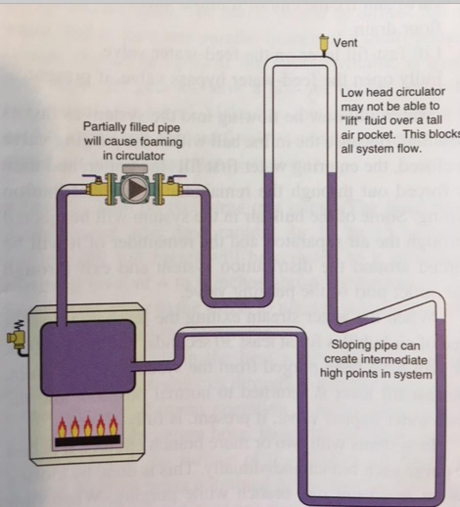 Bob "hot rod" Rohr
trainer for Caleffi NA
Living the hydronic dream0


Categories
- All Categories
- 87.6K THE MAIN WALL
- 3.3K A-C, Heat Pumps & Refrigeration
- 59 Biomass
- 429 Carbon Monoxide Awareness
- 124 Chimneys & Flues
- 2.2K Domestic Hot Water
- 5.9K Gas Heating
- 119 Geothermal
- 168 Indoor-Air Quality
- 3.8K Oil Heating
- 78 Pipe Deterioration
- 1K Plumbing
- 6.6K Radiant Heating
- 394 Solar
- 16K Strictly Steam
- 3.5K Thermostats and Controls
- 56 Water Quality
- 51 Industry Classes
- 50 Job Opportunities
- 18 Recall Announcements