Multiple temperatures on single zone with single circulator pump?

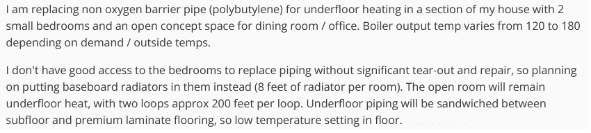
I am replacing non oxygen barrier pipe (polybutylene) for underfloor heating in a section of my house with 2 small bedrooms and an open concept space for dining room / office. Boiler output temp varies from 120 to 180 depending on demand / outside temps.
I don't have good access to the bedrooms to replace piping without significant tear-out and repair, so planning on putting baseboard radiators in them instead (8 feet of radiator per room). The open room will remain underfloor heat, with two loops approx 200 feet per loop. Underfloor piping will be sandwiched between subfloor and premium laminate flooring, so low temperature setting in floor. Because the total space is less than 1000 feet and has similar heating needs, one zone seems to make sense. I'd like to use a single circulator pump, since a standard pump supplies enough flow to run the radiators and the two loops. However, there does not seem to be a "textbook" way of providing separate temperatures without two pumps.
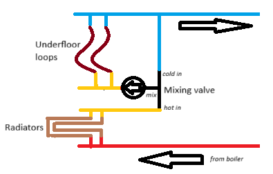
What I'm wondering is if something like this would be worth trying. I need to do the calculations to be sure, but I don't think the water returning from radiators will have lost enough temperature to drop below target temperature for underfloor. Apologies up front for the poor drawing.
Comments
-
I should have also noted this is just one zone in a larger system. The feed and return are from/to the primary loop.
0 -
what about using panel radiators and running one low temperature system. The lower the boiler operating temperature the better the efficiency. Even with cast or non condensing boilers
Do you have a heatloss number for all the rooms? That would help size and select heat emitters
In your drawing how would the radiators return to the “blue” return piping?
Bob "hot rod" Rohr
trainer for Caleffi NA
Living the hydronic dream 1
1 -
I thinking that will be an interesting balancing act between emitter dissipation and the heat loss of the different rooms. You don't want one room 65 degrees and the other 72 degrees. You may need other 'local' control(s) to modulate or bypass the hotter room, assuming the boiler's zone thermostat is in the cooler room.
" In your drawing how would the radiators return to the “blue” return piping? "
I would say through the underfloor loops.
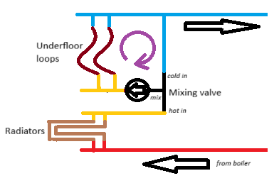
To me, the added (?) circulator (circulator sizing ?) hopefully creates an added parasitic flow through the cold port of the mixing valve (Violet arrow) to lower the Underfloor supply temperature, assuming the return temperature is low enough to do so.
If that is the only circulator in that loop the rooms with the radiators may go through wider temperature swings.
"open room will remain underfloor heat"
What limits the water temperature to this zone now ?
If making them two different zones is like major construction, I'd try it and see how it works out, if it fails well you know what you need to do.
National - U.S. Gas Boiler 45+ Years Old
Steam 300 SQ. FT. - EDR 347
One Pipe System0 -
A second circulator will be the least of your costs here.
You could use the non oxygen barrier loops you can't replace by isolating them with a heat exchanger and using a nonferrous circulator instead of installing new emitters.
0 -
Thanks. That was my first thought, then I looked at the cost of panel radiators compared to baseboard for the size I'd need running at lower temperature. Not in the budget.
Radiators would not return directly to the cold side. Rather they would return through the hot inlet of the mixing valve, through the radiant floor loops, then on to cold.
0 -
I think you will have problems balancing the system. I would use two pumps 1 for the radiant and 1 for the base board.
 1
1 -
Right now there are mixing valves on each line off the manifold (Watts tempering valves). I honestly don't quite know how they are working, because there is a single pump pushing into the manifold, thus pumping into the hot water inlet side of each valve. Each room and the open space have zone valves that turn on or off, controlled by thermostats in each room. Some time back I changed wiring so only the "main" thermostat can turn boiler on (which is in short hallway leading from open space to rooms). I still allow the room thermostats to shut down a zone, even though they can't activate the boiler or pump. One of the rooms will always be colder right now, because the installer apparently didn't put any insulation under piping — and didn't fix after realizing his mistake (I met him some time back, and he was kind enough to tell me why that room is always cold). There is a basement under the rooms. We don't really run the heat down there except on really cold days, but it still stays moderately warm just from the underfloor pipes above.
0 -
I agree about a second circ pump not adding a lot of cost to the project. I just started to think about how I don't need it from a flow perspective — only to pump out of the mix from the valve instead of in to the hot. So that got me thinking about if I could make it flow right with a single pump. My biggest concerns are the unknowns of
1) Will the mixing valve open too much on the cold side to properly flow the radiators? If this does happen, the valve should close cold side back down fairly quickly to satisfy need for higher temp in the floor loops. But the radiators would then "surge" as they rely on draw from hot side of the valve.
2) Will the water temp from the radiators in real-world follow calculated loss to deliver sufficient temp to the floor (especially considering the output temp of the boiler varies…again in theory all good since boiler temp is higher in cold weather…but theory and reality don't always match!
If this seems like something worth trying, I can do so knowing I might need to add the second pump if it does not work. I'll be working with PEX, and set up the layout to facilitate that modification without too much headache.
But…if it's one of those "no way that's going to work" things…
0 -
Also considered the heat exchanger route…very seriously. What pushed me over is the polyb that is about 30 years old, combined with the insulation issue making my son's room cold (yea, he picked that one…have a portable electric he uses if it's too cold). I know a lot of the polyb issues were due to the fittings (checked and we have brass with crimp rings everywhere I can see, so should be fine there). But even if it doesn't leak at some point, when we sell the inspector is going to flag all that problematic pipe.
0 -
Appreciate all the thoughtful comments and thought here! I know this is one of those not-normally-done things, so definitely love that you are seriously considering the design instead of just razzing me for going off textbook!
0 -
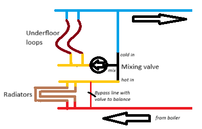
Slight change based on comments about balancing out room temperatures, since I obviously can't just reduce flow on room radiators without impacting floor. Added a bypass line to allow reducing radiator flow in rooms as needed. Agree that balancing would still be fiddly to close down radiators and open up bypass line to get the right temps.
 0
0 -
oh, i misread, i thought it was polyethylene. with pb abandonment is probably the right way to go.
0 -
the main issue with poly B was it did not have an oxygen barrier. Most of it anyways, Infloor had some with an O2 barrier
Without a barrier It would allow O2 into the system dissolving any ferrous material. The hotter the fluid temperature the higher the rate of O2 ingress, so fin tube was a bad match. Certain chemicals in the water could make it brittle
Then the breakdown of metals to magnetite and hematite would sludge the system. In some cases blocking the tube completely
A mod con and or ECM circs will not fare well with PB
Typical thermostatic mix valves are very low Cv, 2-3. What kind of flows are you needing for the two systems? What type of boiler?
With the two systems in series, a manual 3 way valve might be a better option
But we all agree two circs is the best, no guesswork, answer
Bob "hot rod" Rohr
trainer for Caleffi NA
Living the hydronic dream0 -
I can only guess that since you have non Oxygen Barrier tubing, the boiler is a non ferrous material like stainless steel and the pump is stainless steel or bronze. I learned this the hard way by installing a cast iron boiler to replace a GloCore Stainless steel boiler on a non barrier tubing system. It was a disaster. After 2 years of operation, the tubing was caked with mud from all the oxygen entering the system and causing the CI Boiler to turn to rust. Once I figured out the floor heat was non barrier tubing, I needed to flush all the tubes individually with high pressure water (and there were 4 zones with 16 or more loops per zone) then I purchased a stainless steel heat exchanger to separate the boiler from the floor system. I could go on forever about that job, but needless to say I learned an expensive lesson there.
So now you have a 4 loop zone that has 2 loops that you need to replace for some reason. Your 3/4" fin tube low cost baseboard radiators will be a good choice however you need a second circulator in order to get the proper flow thru the baseboard radiators and you need to get the lower temperature loop to operate independently of the high temperature loop. I can illustrate this using hypothetical flow rates and temperatures using your drawing
The exact temperatures and flow rates will vary based on your actual as-built system. The temperatures and flow rates are for illustration purposes only.
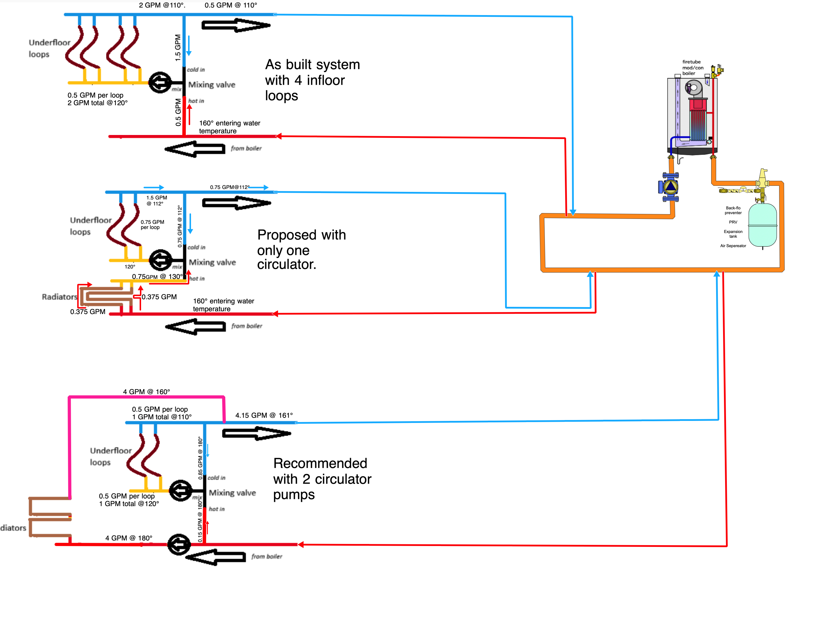
I am guessing that the zone you are referencing may have looked like the top zone in this illustration. Radiant loops on average have a flow rate of 1/2 GPM and the low temperature should not go over 120° With that in mind that zone will circulate about 2 GPM under normal steady state conditions. the temperature drop across that floor will be about 10°. So that is how I guesstimated the temperatures and flow rates
************************************************
Looking at the second (middle) zone is your proposed piping arrangement with only one circulator. The pump will have only 2 of the original 4 loops to push water thru. Since that pump will end up a little higher on the pump curve, let’s say that the pump will try to force ¾ GPM thru that remaining two loops and that will be a total of 1.5 GPM to the zone. But that is thru the radiant floor loops after it gets mixed. So how does that hot water get to the mix hot in port? You pull it thru the baseboard radiators and that 160° water will drop in temperature as it goes thru each of the two radiators. As those radiators give off their heat from the 160° supply water, the exiting water from those radiators may drop below the 120° needed for the low temperature floor…. But let's not consider that possibility and think positive. The water now entering the HOT inlet to the mix valve might be 130° and you will need to mix the 112° return water into the mix valve cold inlet to get the 120° low temperature. The reason the return from the radiant floor is only 112 is because it moved thru the floor faster at ¾ GPM as a result of your redesign. Now that lower temperature Hot water will need less Cold water to mix to get 120° the numbers might look like this:
112° at .75 GPM and 130 @ .75 GPM will get you 120° 1.5 GPM so the hot water entering the zone is no longer 2 GPM but has dropped to 1 GPM and the temperature drop is less. It might work fine in mild weather, but that equals less BTUh delivered to that zone. You will not find this out until the coldest days of the winter when you can least afford to turn off the heat to redesign the system.
************************************************
The bottom design will allow you to move 4 GPM 180° water thru the baseboard heaters in order to get maximum capacity from them. The radiant floor will also be able to have the flow adjusted to the 0.5 GPM for each of the two remaining loops. You will also need to add a circulator relay and a thermostat in that zone in order to operate the high temperature pump. The high temperature pump must be stainless steel or bronze since it is located on the system that is connected to the non-barrier tubing.
If you ever get a new boiler for any reason, you will need to stay away from steel or cast iron boilers, or you will find out the hard way like I did about that problem. Stainless steel heat exchanger, copper heat exchanger, or aluminum heat exchanger boilers are the only ones you can choose from. But check with the boiler manufacturer before you connect it to your non-barrier tubing system.
I hope this helps you to understand that your idea, in concept may make sense, but in reality may not work satisfactorily.
Mr. Ed
Edward Young Retired
After you make that expensive repair and you still have the same problem, What will you check next?
0 -
As drawn, it can't work.
There is nothing to drive cold water flow through the mixing valve. Water needs a pressure differential to flow, the pressure at the tee on the outlet is going to be lower than at the mixing valve, nothing is going to cause water to flow in that direction. Mixing valves don't suck.
With no cold water flow, the mixing valve will shut if the water presented to it is warmer than the set point. The entire flow of the circuit flows through the mixing valve, so when that happens the entire circuit shuts off, dead-heading the circulator. Depending on the circulator type that might be something you want to avoid.
The only way this can work with one circulator is if the two parts are in series. There is some chance — although vanishingly small — that both parts can deliver their optimal performance with the same flow. If not, you can put a bypass pipe with balancing valve on the part that needs less flow.
I suspect that this system has never worked. As a general note — more to the other readers of the forum — the biggest mistake you can make with hydronics, and we see it all the time, is to assume that things will "just work." People are pouring a concrete slab, and they assume that so long as the put in as much tubing as will fit everything will work out. It won't. These systems need to be engineered.
I know this is not the answer you want to hear, but before investing any time or money into this system I would do some back-of-the-envelope engineering to determine whether it's actually possible that it could ever work. That means doing a room-by-room heating load calculation and then estimating the heat-providing capacity of the radiators and the in-floor loops, and seeing if there is any combination of flows where both can provide the proper amount of heat needed for their respective rooms. This is important because there is no guarantee that they can; instead, I would say it's rather unlikely.
0 -
As drawn by OP, the setup will work. The key is to have only a reasonable delta T across the high temp loop. 8' of baseboards won't drop the temp much and won't be all that much extra pressure drop. Essentially the baseboard will look like an extra long supply pipe to the low temp zone.
I wouldn't bother with any bypass, get baseboards with adjustable louvers for local temperature control. If you want to get fancy, you can get a zone valve as a bypass with a local thermostat (you'll need a valve on the baseboard to add a bit of restriction for this to work).
8' of baseboard is on the small side if you want to use lower water temps. I would go for a bit longer, never hurts.
0 -
is it worth the experiment for the cost of an additional circ?
Find them on ebay for 35 bucks, usually.
Then you have the flow and control you really desireBob "hot rod" Rohr
trainer for Caleffi NA
Living the hydronic dream0 -
@hot_rod, since this system operated with non barrier tubing, I'm guessing that the SS or Bronze pump is not going to be that low cost
@Kaos says "it will work." but ALL of the water being pushed or pulled thru that zone (look at my middle illustration above) MUST flow thru 2 radiant floor tube loops. The existing pump was fine moving about 2 GPM thru 4 tubing loops. I don't believe that you can get the same BTUh thru just 2 loops using that same pump. My guess is that @inaun is not purchasing another pump with more GPM and pump head to do the job. My guess is that they are going to use the existing pump. The design is flawed.
@DCContrarian indicated "I suspect that this system has never worked". I might disagree with this. 800 feet of polybutylene pipe was an older radiant floor system. look at the top piping design in my illustration above. I had a customer with one of these systems. The brand name was InFloor ™ and I found out the hard way about non barrier tubing when replacing a SS HX boiler with a CI boiler.(see my previous post). I have a feeling that the four 200 foot loop zone worked fine for many years, along with all the other zones that were most likely installed the same way.
I believe that this project for replacing 2 of the 4 loops with baseboard MUST use 2 different pumps. One pump for the 4 GPM flow rate thru the high temperature loop, the existing circulator pump for the remaining two radiant floor loops.
@inaun…. One more note to clarify the baseboard loop. Do not install the 16 ft of baseboard as two separate parallel loops. 16 feet of baseboard is small enough to be one series loop and will be easier to purge air from the single loop
Edward Young Retired
After you make that expensive repair and you still have the same problem, What will you check next?
0 -
In the original drawing, what would make any water flow down from the tee drawn in blue? To the extent there's any pressure difference, the pressure at the tee is going to be lower than at the mixing valve, water will want to flow up there.
0 -
Here's what I see as the fundamental problem with this layout: the water flow through the radiators is going to be the same as through the in-floor tubing. Which means that the control strategy for both has to be the same. But the optimal control strategies are very different. So even if you could get it working where the flows and temperature drops are what you want, it's not going to be able to deliver consistent comfort.
0 -
@EdTheHeaterMan The setup doesn't need the same flow as the extra heat now comes from higher supply temperature, instead of 4gpm 10f delta, you run 2gpm 20f delta. With a modcon, higher supply temperature is free as long as the RWT is about the same which would be in case of a series setup.
@DCContrarian The pump creates a low pressure at the inlet, depending on the position of the mix valve, it will "suck in" water from the blue T without issues. Control can be a challenge but as long as the baseboard emitters are oversized, you can always close the louvers on it to reduce output. You don't have individual control of the series zone, but could be set up to get a reasonable balance.
0 -
If the series configuration has to be used, I would not fool with louvers I would have a normally closed (in series with the baseboard) and a normally open (in parallel (bypass) with the baseboard) zone valves controlled by a local thermostat in the baseboard room to limit the temperature.
No call for heat it is 100% in bypass mode, with a call for heat the bypass is closed off and the full flow is through the baseboard. It would not control the circulator or the boiler.
National - U.S. Gas Boiler 45+ Years Old
Steam 300 SQ. FT. - EDR 347
One Pipe System0 -
There is a lot of ideas being floated here. I would like to know what @hot_rod, @109A_5, @mattmia2, @Kaos and @DCContrarian think regarding diagram B and Diagram C below. Without more input from @inaun I can only make assumption that in my illustration A = something that has been working fine for years and now has 2 bad poly tubing loops that need to be addressed.
The poly tubing does not have an oxygen barrier
That means that the boiler and all the accessories are not cast iron or steel. They all must be made of Copper, Bronze or Stainless steel. Can we all agree on that?
Trying to fix the "failed tubing" heated area with copper baseboard it the lowest cost way to replace the heat in the rooms that no longer have working floor heat. Can we agree on that?
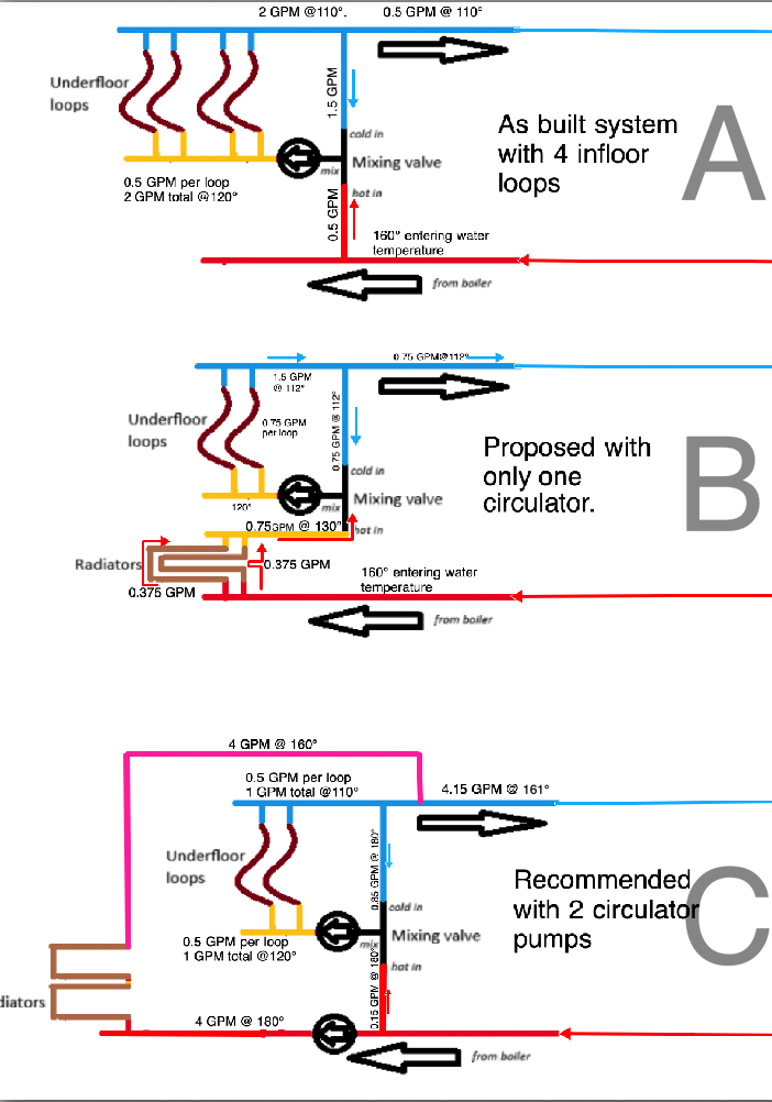
What @inaun wants to do is the lowest cost way that will work. One of the ideas floated is to use the existing circulator to move heated water through both the baseboard and the radiant floor tubing with no actual control over the flow rate except for the manifold connections from the working tubing loops, as illustrated in diagram B above. I personally don't see it providing 10,000 BTU of heat in the way that diagram A is providing. 10,000 BTU of heat (2 GPM @ 10° ∆T) You can not get the same amount of heat that 4 poly tubes can provide when you are trying to put that same amount of heat thru 2 poly tubes. It ain't gonna happen.
Does anyone thing that you can? Really?
Does anyone think that diagram C is not going to work? If not, why not? With the proper relay you can operate both pumps with the same thermostat. It is just gonna cost a little more to buy a new bronze or stainless pump and a relay to operate it. Not ideal for keeping cost down, but when the temperature drops to design temperature, @inaun will find out too late that diagram B was a mistake.
Edward Young Retired
After you make that expensive repair and you still have the same problem, What will you check next?
0 -
@EdTheHeaterMan personally I would go with your recommended 'C' option with each circulator being its own sub zone (I believe they are separate rooms), since that will most likely provide the best comfort control. If for @inaun that is not doable i'm just providing other ideas / options. As I stated early on in this thread the OP's original idea may have issues as far as comfort control.
Messing around with louvers throughout the heating season sounds very irritating to me, I'd rather automate the process.
I also kind of like @mattmia2 heat exchanger isolation idea. However that requires more plumbing hardware than just a heat exchanger. So the cost may be higher, but the OP would not have to buy and install new baseboards.
National - U.S. Gas Boiler 45+ Years Old
Steam 300 SQ. FT. - EDR 347
One Pipe System0 -
@109A_5 said: "
I also kind of like@mattmia2heat exchanger isolation idea. However that requires more plumbing hardware than just a heat exchanger. So the cost may be higher, but the OP would not have to buy and install new baseboards."Why would a heat exchanger be needed. If the non barrier tubing worked on the existing system I would bet that there are more than just the one 4 loop zone has non barrier poly tubing in the other zones. The system is already operating without a HX. Perhaps I'm reading the issue incorrectly. but I understand that this is one of several secondary zones piped as a secondary loop. @inaun has indicated that the system is older, before oxy barrier tubing became popular. This is very much like the huge mistake (learning experience) i made when one of these non barrier systems needed th have the boiler replaced. That polybutylene tubing in a thin pour concrete slab over a crawlspace worked for over 20 years with all that oxygen because the original boiler was stainless steel.
So adding a HX to @inaun system seems like @mattmia2 has assumed that the existing poly tubing is the problem and not the fact that it needs to be replaced for reasons not exactly articulated in the original comment, ( I think it has a unrepairable blockage or too many pinhole leaks to easily resolve) but is not easily accessed. The balance of the non barrier poly tubing in all the other zones are not a problem that require a HX so why would a HX help here?
I certainly wish that @inaun might come back and better explain the rest of the system and perhaps offer the type of heating source there is for that particular secondary loop. The fact the they said "
However, there does not seem to be a "textbook" way of providing separate temperatures without two pumps" indicates that they have done some research and understand that no one has successfully done what they want to do and published the results. I think that's because it won't work.Edward Young Retired
After you make that expensive repair and you still have the same problem, What will you check next?
0 -
I think this pretty well explains the situation and why a heat exchanger type configuration possibly could work. I guess it depends on how the old pipe in the bedrooms was installed.
 National - U.S. Gas Boiler 45+ Years Old
Steam 300 SQ. FT. - EDR 347
One Pipe System0 -
The fluid will take the path of least resistance, all it knows is getting back to the return of the circ,
So the circ with the least flow resistance will get the most flow
A dynamic balance valve like a Caleffi 127 might work. It maintains a fixed gpm within its delta P range
Bob "hot rod" Rohr
trainer for Caleffi NA
Living the hydronic dream 1
1 -
Going back to first principles, the point of a heating system is to provide comfort, and the way to do that is to match the delivery of heat to the heating load. For any radiator — and a heated floor is a radiator — at a given room temperature the amount of heat delivered is entirely determined by the entering water temperature and flow.
A problem with the original design is that both sides get the same flow through the circulator, the entering water temperature is constrained for both sides, so there's no way to adjust the heat output of one side independent of the other. And unless both sides are equally well-matched to their heating load it's going to be hard to find a point where both sides are comfortable.
With two circulators you can set the flow of each side independently, and thus the heat delivery.
An issue you're going to run into is that heated floors tend to be difficult to control, because they have so much heat capacity that a standard on/off thermostat is going to overshoot wildly. A baseboard radiator works pretty well with an on/off thermostat because it has low heat capacity and responds pretty quickly to changes in the flow. I'm going to posit that one thermostat controlling both sides of the circuit would actually do a pretty good job, that at any given time the portion of total capacity needed by either side is roughly the same. So if the baseboard radiators need to run 15 minutes on/ 15 minutes off to serve the heating load, the heated floors will probably also do a pretty good job with the same duty cycle.
1 -
@DCContrarian said: "With two circulators you can set the flow of each side independently, and thus the heat delivery."
I call that one an agreement that @inaun's single circulator design is not going to work and that you need two circulators.
Edward Young Retired
After you make that expensive repair and you still have the same problem, What will you check next?
0 -
After writing my comment above, I went back and read the original post again, and I tripped over this sentence: "Boiler output temp varies from 120 to 180 depending on demand / outside temps."
This is an excellent way to modulate a heated floor. However — and this is a big however — it's going to work at cross purposes with a thermostatic mixing valve, they're going to defeat each other.
This type of control is called "outdoor reset." It's a premium control. I'd be thinking about getting rid of the mixing valve and just letting the outdoor reset control the output.
0 -
"This type of control is called "outdoor reset." It's a premium control. I'd be thinking about getting rid of the mixing valve and just letting the outdoor reset control the output."
So based on the fact that the boiler has ODR for the rest of the zones, all that is needed is to remove the mixing valve? Is this how you see it @DCContrarian
And what water temperature would you select for a design day to operate two 8 ft sections of Baseboard radiators piped parallel to each other? Then what water temperature would you expect to enter the radiant floor tubing in this case?
I still believe that you need two circulators to get it to work properly.
Edward Young Retired
After you make that expensive repair and you still have the same problem, What will you check next?
0 -
The range of the outdoor reset is too small to be the only control.
For a given radiator and a given water flow, the heat output is proportional to the difference between the water temperature and the room temperature. Assume your hottest water is 180F, at design conditions, and your coldest water is 120F. At 70F room temperature that's a difference of 110F to 50F. So the minimum heat output you can get is 50/110= 45% of design output. Let's say design temperature is 0F, at 38F the 120F water is meeting the design goal; if it's any warmer out you need to start turning the circulator on and off with a thermostat. Which is fine, it's not complete control via outdoor reset but it's pretty simple.
With two radiators in series, the same rule is true, and the temperature at their junction changes as the incoming water temperature changes. So if you could get a configuration of a baseboard and underfloor in series with the right flow so that when the incoming water is at 180F, both the baseboard and the underfloor meet their heating loads, it will work. There's no guarantee you'll be able to get such a configuration to work, but if you can it can work.
What would it look like? Let's spitball some numbers. Let's say the maximum temperature you can send to the underfloor is 120F. Let's say you have 16 feet of baseboard rated at 550 BTU/ft with 170in/150out water. That would nominally produce 8800 BTU/hr with a flow of 0.88 GPM. If you slow the water down so that it exits at 120F with 180F in, I get that your output is 7822 BTU/hr and flow of 0.26 GPM.
If your underfloor can meet the design heating load with 0.26 GPM of 120F water, then everything works at all temperatures. Just put a thermostat in the room with the baseboards to control the circulator and let it rip.
What happens if it can't? If the underfloor needs less flow, then you could bypass some of the flow. But if the underfloor needs more flow, you're confined by the fact that heat delivered is always equal to temperature drop times flow times 500. If you want the baseboards to drop the water from 180F to 120F, then the greater the flow, the more heat the baseboards have to shed. If that's more heat than the load of the room, the room will overheat and comfort will suffer. There's no way around it.
At that point you have to delink the two rooms, put each on its own circulator and thermostat or other control mechanism.
0 -
Thinking more about my previous comment, it occurs to me that if you have two radiators in series, the relative amount of heat each one puts out is proportionate to the temperature at their midpoint. So if water is leaving the boiler at 180F, returning at 100F, and the midpoint is at 120F, the first radiator is going to have three times the output of the second one. There's just no way around it, heat delivered is flow times temperature change times 500.
Since the point of the radiators is two replace two underfloor circuits, I think it's safe to assume we want the outputs to be roughly equal. Which means the upper limit on the water is going to have to be pretty low to keep the underfloor within range.
Going back to @EdTheHeaterMan 's diagrams above, I'm thinking the way to go is something like diagram C, but instead of using a thermostatic mixing valve just using a tempering valve. That way the outdoor reset on the boiler still affects the water temperature but you can have hot water going to the underfloor circuit and mixed down.
0 -
@DCContrarian what is the difference between a tempering valve and a mixing valve?
Edward Young Retired
After you make that expensive repair and you still have the same problem, What will you check next?
0 -
Sure, what I mean is a non-thermostatic valve that just mixes the two sides in a constant proportion. So as the outdoor reset modulates the leaving water temperature the mixed water temperature changes proportionally. The goal is to be getting the benefit of outdoor reset at temperatures the underfloor can use.
0 -
is such a valve available at a reasonable cost @DCContrarian ? I know of a motorized valve from Taco that will take the already reset water for the higher temperature radiators and reduce it to a lower temperature reset for the floor heat. “ Resetting the reset”
that valve plus the accompanying outdoor and pipe sensors and accessories will cost the OP over $800.00. Dollars plus whatever labor and markup might be included to make the project well past the $2000.00 mark (just guessing not an actual price quote). That is probably not an option in this case since the OP was trying to get it done using only one circulator.
I believe my 2 circulator suggestion with an inexpensive tempering/mixing valve fits the bill here
What do you think?
Edward Young Retired
After you make that expensive repair and you still have the same problem, What will you check next?
0 -
Maybe I've been misunderstanding all along, but when the OP talked about a mixing valve I assumed it was a thermostatic mixing valve.
I think we're on the same wavelength, I'm talking about a simple valve where you set the balance of the flow and forget about it, something like this:
https://www.supplyhouse.com/Bluefin-ASV050-1-2-Brass-Anti-Sweat-Valve-w-Nuts
That's not exactly right but it was the quickest thing I could find. You could even just have a tee and balancing valves inline on the hot and cold supplies. The idea is that it's going to keep roughly the same proportions of hot and cold regardless of temperature — and roughly is good enough.
0 -
So you want to repurpose a toilet tank device for radiant floor heat. Is this a normal industry practice? This is the first time I'm ever hearing about it. Have you actual experience with this design? You should write a white paper on the proper way to make it work. I believe that there are not too many experienced professionals with this as part of their wheelhouse of design options. Perhaps you can get together with @ethicalpaul and make a video on the features and benefits of non thermostatic mixing valves on radiant floor design
Edward Young Retired
After you make that expensive repair and you still have the same problem, What will you check next?
0 -
In my post I said that's not the right piece, just the first one I could find.
What would you rather? A thermostatic mixing valve with outdoor reset? So they can fight each other?
0 -
While they look identical
A mix valve has two inlets, one outlet
A diverter has one inlet, two outlets
They serve opposite functions, they can be thermostatic, motorized or manual
Bob "hot rod" Rohr
trainer for Caleffi NA
Living the hydronic dream1


Categories
- All Categories
- 87.6K THE MAIN WALL
- 3.3K A-C, Heat Pumps & Refrigeration
- 59 Biomass
- 429 Carbon Monoxide Awareness
- 124 Chimneys & Flues
- 2.2K Domestic Hot Water
- 5.9K Gas Heating
- 119 Geothermal
- 168 Indoor-Air Quality
- 3.8K Oil Heating
- 78 Pipe Deterioration
- 1K Plumbing
- 6.6K Radiant Heating
- 394 Solar
- 16K Strictly Steam
- 3.5K Thermostats and Controls
- 56 Water Quality
- 51 Industry Classes
- 50 Job Opportunities
- 18 Recall Announcements