Water to Water Geothermal heat pump replacement with lp boiler
Comments
-
a clamp on probe will get you the temps. the pressure is less important, the temps in different places will tell you a lot about the flow. I'd pull one of the circulators with the isolation valves and see if there is a flow check in the circulator. If there is and it is undamaged and you are getting ghost flow you have problems with the way the circulator for the zones and the circulator for the heat pump are connected together.
0 -
It’s hard to beat eyes on the ground. Hopefully you have a knowledgable hp expert on the way.
You have a good list of questions here to get answers for.
Bob "hot rod" Rohr
trainer for Caleffi NA
Living the hydronic dream0 -
Please report back if he figures it out. Inquiring minds want to know!
0 -
That is outside my wheelhouse but I will look around and see if I could find someone I would contact Water Furnace and ask their input and suggestions for a technician. Here is a link to their dealers close by. Water Furnace
Ray Wohlfarth
Boiler Lessons0 -
I called and talked to a rep from Water Furnace and he directed and recommended me to a company. They are out of Latrobe which is relatively close to me. I contacted them about stopping out so I'm crossing my fingers and hoping they actually follow through.
 2
2 -
Hopefully he recommended someone good. I think WF is pretty good stuff.
Let us know how you make out.
0 -
Were you able to calculate gallons per minute at 8 dt? you can see how much heat you were extracting.
0 -
Supposed to be meeting next week. Will update once they assess the current system.
0 -
How close are the drilled grouted wells to each other?????????????????????????????????????????????????????
When you said three 180 foot deep wells piped in series that struck me as very odd. These drilled wells were apparently drilled and had a looped drop pipe system installed with the "so called "geothermally enhanced" clay grout that acts as an insulator rather than an open loop system.
You may have one problem which could simply be the 3 wells are too close together and cannot shed the heat or reclaim enough cold from the surrounding ground-go figure-due too shallow a depth.
The driller that did this did you no favors as a 600 foot deep open loop cased well with a six inch pipe cap on the first pipe joint with a marine concrete plug in the last 10 feet of the casing would have given you almost 590 feet of water column for heat exchange with a single drop pipe set in the first 200 feet of water column.
0 -
I just looked at the drilling information from the driller. Cores were 180' deep all shale and limestone and a little coal. He sealed with benseal. 3/4" pipe. All wells are 17' apart. He laid them out in a triangle.
0 -
UGH, I hope the problem is in the heating/cooling systems basic adjustments or a circulator that is allowing ghost flow.
0 -
you can only hope.
0 -
Well the geo company came out yesterday. He did flush the wells and they were exceptionally dirty. He seems to think one of the wells wasn't flowing and a bunch of crud got built up in ot over the years. He said the way the system was laid out could have been the issue and the absence of a buffer also isn't helping. He did pressure test the wells the best he could qith the flush cart and everything was fine. Unfortunately he doesn't seem interested in trying to fix anything or trouble shoot because the equipment is so old. New heat pump and buffer was his recommendation. And different pump layout for the zones.
0 -
He did not check the system btu output.
0 -
was there glycol that had not been maintained in it?
0 -
Yes
0 -
maybe others will have a different perspective, but i don't see how an appliance that has probably a 20+ year payback period and seems to be retaining its water and refrigerant is "too old".
0 -
I am genuinely sorry to see that you are saddled with this.
0 -
If your goal is to provide good service to your customers at a reasonable price, I could see why it's not a good business decision to get involved with a 20-year-old piece of equipment that may never have been properly installed to begin with.
0 -
One thing is that I know the wells are ok.
Replacement of the geo equipment is a pretty large expenditure. After lackluster performance of the old system I'm hesitant.
So now I just have to decide whether I want to spend that much on the new geo equipment or switch over to a modcon boiler and heat pump for ac (hooked to existing ductwork).
0 -
i'm not convinced that there is any problem with the appliance, the way the load loops are piped looks very questionable, that it doesn't have a good way to get the right flow through the appliance.
Given everything else refrigeration now, it is likely to outlast a new one by decades.
It looks like the piping is very much separable from the appliance itself, that a new appliance could be installed pretty easily if it fails after the piping is corrected. If it is piped correctly you should be able to just as easily add a mod con to the loop as the heat pump by connecting both with closely spaced tees.
0 -
I just checked the pressure drop and ewt again and looked at it on the charts in the manual. I got once again a 2 psi pressure drop. Adding correction factor for 70 degree ewt changes it to 1.86 psi pressure drop. Looking at the charts in the manual the minimum pressure drop is 2.9 psi which is 11 gpm. Recommended pressure drop is 6.2 psi which is 16.5 psi. I'm not sure how to interpolate my pressure drop to gpm because i cant find a chart for that. It doesn't seem there is a straight correlation to figure it out.
0 -
Maybe @hot_rod will chime in but this it what I think.
Recommended pressure drop is 6.2 psi. At 6.2 psi pd the flow should be 16.5 gpm per the mfg.
you say that you have a 2.0psi PD and that the mfg says 2.9pd is minimum and that at 2.9 you flow would be 11 gpm.
At 2.0pd you flow is only 9.53 gpm (thats what I came up with) Cv of the unit is 6.74.
so at 9.53 gpm your flow is only 86% of the mfg MINIMUM
and 57% of the recommended MFG flow.
No surprise to me why the unit short cycles and has no capacity.
You need someone who can size the correct circulator for you to get the proper flow. Too many installers guess. That doesn't work for me.
Sometimes they get away with that approach but more often they fail. Heat pumps need the right flow
 1
1 -
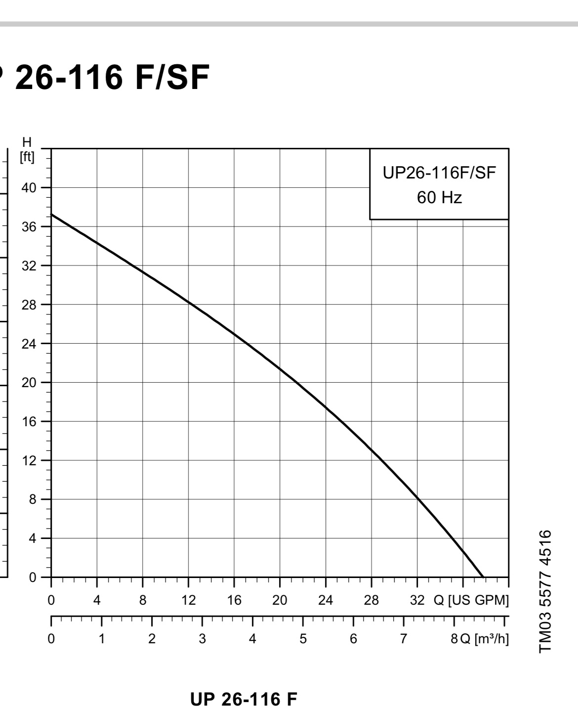
Pump in the flocenter is a grundfos up26-116
0 -
Or the load side might need to be modified so that it is primary secondary, it looks like it is plumed so the zone and heat pump circulators are interacting with each other now.
0 -
The manual specifically says if job requirements are outside the pump curve an alternative pump will need to be obtained. How do i go about figuring out the head loss? The furthest well would be about 40' of 1" sdr11 and the furthest well is 180' deep of 3/4" sdr11
0 -
So we start here:
the three bores are 180+180+180= 540 feet deep
Each bore has two drop pipes 180 feet long=360 of drop pipe per bore times three equals 1,080 feet of pipe plus the pipe from the home to the first well then 17 feet to the second well and 17 feet to the third well and the return pipe to the water furnace from the last well.
540 times 2 the number of drop pipes plus 100+- feet from the last well to the water furnace plus the length of the first pipe 100+- feet from the water furnace to the first well, SO you could say you have a total run of pipe of 1,200 feet+- of one inch pipe SO…………………
0 -
I found geoflo website has a bunch of calculators. It came up with 16.5 gpm at 55.5 ft hd. Not sure if that seems reasonable or not.
0 -
That would require a 2 pump geoflo unit
0 -
I would go to the PPI website and use the free calculator to come up with an accurate number. Pressure drop , for the tubing runs
Select tube type, diameter , lengths and type and % of fluid used
Do the well loops then the piping to and from and any inside piping
Then start looking at the pump curves to see which you need to get the gpm at the head the calculator gives you
The 116 will give you 12 gpm at 28’
A WAG that should be enough pump unless there is an obstruction ? Plugged Y strainer perhaps
Any idea what size pump he had on the flush cart, that would give you some reference
I have seen those geo pump stations with 2 and even 4 pumps used
The 4 pumps are push pull
 Bob "hot rod" Rohr
trainer for Caleffi NA
Living the hydronic dream1 -
It was a geoflo 3788 cart. Geoflo website says 1.5hp pump 115v. I don't think there are any strainers on the source side, nome that i can see external. Unless it is inside the heat pump housing. The pump that is currently in the geoflo unit is a UP26-116
0 -
if in fact the pump spec is 16 gpm at 55’, that 26-116 isn’t giving you the flow. So you have two pieces of data, the unit has never worked properly , and the spec sheet indicates it is under pumped?
The GEO service person should have picked up on this, seeing all the equipment and knowing the well spec?
The manual for the HP should indicate required flow and related pressure drop
Bob "hot rod" Rohr
trainer for Caleffi NA
Living the hydronic dream0 -
on many days i also feel like i am the only person in my office that understands math…
0 -
here us a You Tube that may be helpful fir sizing the pump station
Bob "hot rod" Rohr
trainer for Caleffi NA
Living the hydronic dream0 -
Using the optimistic pipe material choices in the Geo-Flo ground loop calculator with what I understand as your loop parameters works for your existing ground loop pump at around 12gpm. I would confirm all construction details and play with that calculator if you don't have the ground loop documents. The documents would have the design parameters to justify the equipment choices. The calculator has entries for the heat pump heat exchanger pressure drop which needs to be factored in. You can confirm that in the heat pump installation docs at a certain assumed gpm to use in the calculator.
If you have to install a second pump it looks like it can be added to your existing pump station. The existing pump is out of production but you can find one with similar head/gpm if you need to, or maybe find one on eBay. The downside of more gpm and a second pump is more watts. Two pumps is going to be 500W+. Lower gpm = less power overall.
If the ground loop was all clogged up and the pipes can be confirmed in the model best case, maybe you will have solved/improved your situation.
0 -
By the way, Btu/hr (Q) = 500 * GPM * ΔT, is the rule of thumb for heat transfer. Looks like a general design rule for ground loops is a ΔT of 7F to 10F.
500 * 12gpm * 10F ΔT = 60k btu/hr
0 -
Ive mentioned the single pump issue maybe not providing enough flow numerous times, both to the original installer and the person that just came out. In all occasions they looked at me like I was crazy.
0 -
Ill check the delta t on the source side today because I didn't do that yesterday.
0 -
It sounds like you have two major issues. Clogged field and lack of buffer tank. Sounds like the field is now fixed so all you need is to add a small buffer. Even the bigger pump if needed, won't change the operation much and not really the cause of most of your issues.
Neither one of those means replacing the a heat pump that is still working. Adding a simple in-line two port buffer can be done by any boiler tech.
As for replacement when it does actually die, I think your best bet is to find a better geo tech that can install a new unit.
Propane replacement doesn't make sense as it costs almost the same as resistance heat. About the only non-geo replacement is to replace the air handlers with ducted cold climate heat pumps and keep the resistance backup boiler for any floor heat. You can run the heat pumps for bulk heat and the floor heat only enough to take the edge off any cold slab.
 1
1 -
Here are some buffer tank piping options. The 3 pipe, direct to load brings the best of 2 and 4 pipe methods. Most HP manufacturers have embraced this method, for both GEO and air to water HPs..
You need a tank with at least 3 connections to do this correctly. Most buffer specific tanks are 4 port now.
an example from GEO-Flo and Caleffi
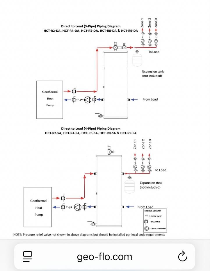
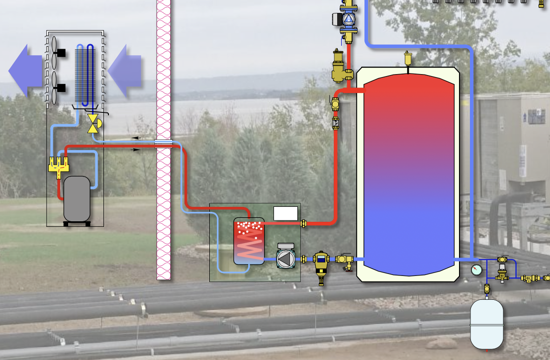
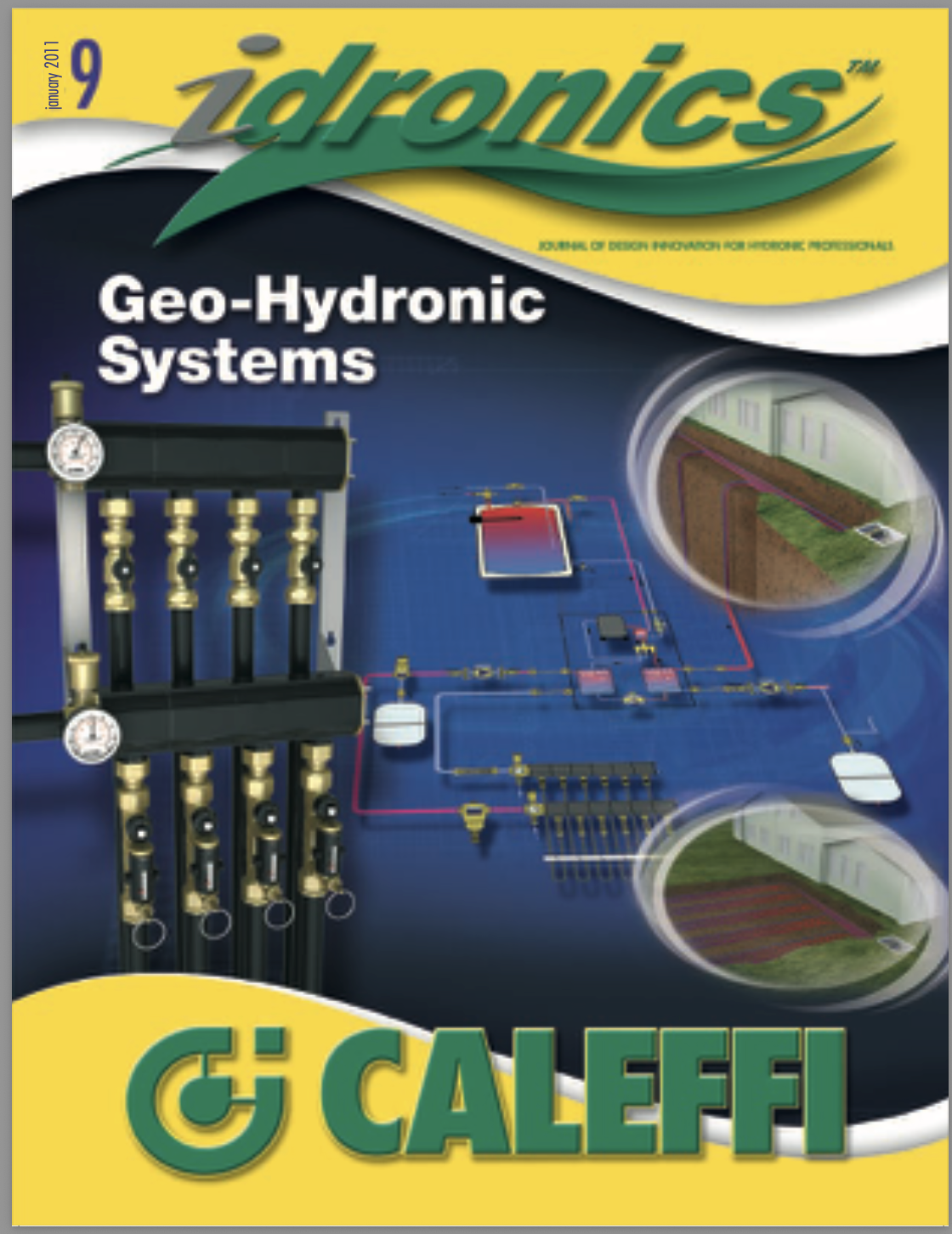
A deeper dig into GEO theory and design in issue 9 of Idronics. This issue was put together in 2011 before we started promoting 3 pipe buffer tanks it shows 4 pipe tank piping. A link to all Idronics below
 Bob "hot rod" Rohr
trainer for Caleffi NA
Living the hydronic dream0


Categories
- All Categories
- 87.6K THE MAIN WALL
- 3.3K A-C, Heat Pumps & Refrigeration
- 59 Biomass
- 429 Carbon Monoxide Awareness
- 124 Chimneys & Flues
- 2.2K Domestic Hot Water
- 5.9K Gas Heating
- 119 Geothermal
- 168 Indoor-Air Quality
- 3.8K Oil Heating
- 78 Pipe Deterioration
- 1K Plumbing
- 6.6K Radiant Heating
- 394 Solar
- 16K Strictly Steam
- 3.5K Thermostats and Controls
- 56 Water Quality
- 51 Industry Classes
- 50 Job Opportunities
- 18 Recall Announcements