Trane dual stage heat but single stage AC control 2 stage AC now? control question

I have a question that's right up your alley as far as controls goes but maybe the overall AC piece if there is an issue you're not sure of someone else can chime in and say why not to do it.
My sons house has an older but in great shape furnace Trane XL90 TUX100R series but his much older and not in as great shape R22 Carrier condenser unit sprung a leak and rather than repair it we just opted to get a new evap coil and condenser and lineset to go to R410a system and not worry about cleaning out the old R22 stuff for reuse. The new condenser is a York modulating AC only unit HMCG2 series. I never considered I would have any issues until today when I was wiring everything up. I saw that the condenser has 3 wires C,Y,and an S1 wire terminal that goes to the y/y2 terminal on the furnace. Problem is the Trane only has a SINGLE (UGH) stage cooling control board, not a dual stage like the heat side.
The question I have for you on the control side is if I move the G wire from the terminal on the nest thermostat over to the y1 terminal (assuming G on the furnace is typically a lower speed on the fan) and y1 over to the y2 (assuming this would be the typical single stage AC fan speed). I would then look to connect the original Y at the furnace now on the G and the condenser y onto the G then to simulate a second stage I would connect the s1 from the condenser to the Y terminal on the furnace with the original Y (now Y2) from the Nest.
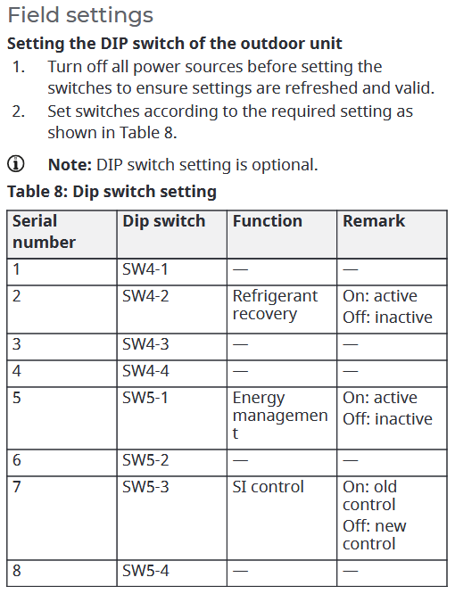
I know I should have looked at this before getting everything assembled (just waiting on lines to be brazed, vacuum and pressure tests now) but when I looked into his furnace and saw 2 stage and how immaculate it was I didn't even realize it was just 2 stage for the heat and 1 stage for the AC. I figured maybe something like I described above may give him some of the benefit of the higher efficiency condenser until the furnace does crap out then we will make sure to get a much better unit to make everything work together as drawn on the diagram. Otherwise I'll see if there is a way in the settings or DIP switches to keep the condenser running in a single stage mode.
Thanks
Pete
Comments
-
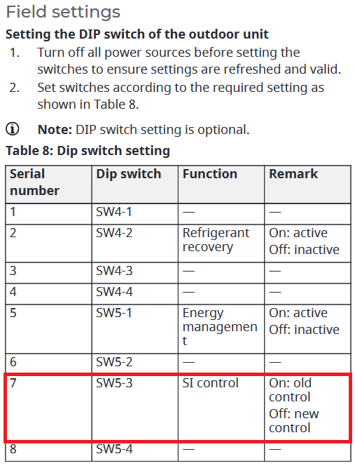
In the manual S1 and SI seem to be the same, however I not sure if that is so. Two S1 modes ? Dip switch SW5-3. Looks like the S1 may be an output from the condenser unit that controls the blower speed by monitoring system conditions or just time. In which case the Y2 from the NEST may confuse things.
 National - U.S. Gas Boiler 45+ Years Old
Steam 300 SQ. FT. - EDR 347
One Pipe System2 -
If the air handler is only one stage cooling, that means it only has one fan speed for cooling.
To understand two stage cooling, you've got to realize that it's not y1=cooling, y2=more cooling—you get a better understanding if you think of it as y2=cooling, y1=less cooling. Many two stage furnaces will have the cooling terminals labeled Y1 & Y/Y2, Y1 for low airflow during stage 1 operation, Y/Y2 for non-staged or high stage cooling.
Simplest solution is to wire the condenser as single stage, but there might be a cleverer solution. If the furnace has a separate G call fan-only speed that's independent of the heating and cooling speeds, you may be able to adjust that speed to the correct airflow for low cool, then it's just a matter of adding enough controls (probably a single relay) to pass only a G call to the furnace in low cool mode.
0 -
Thanks @ratio
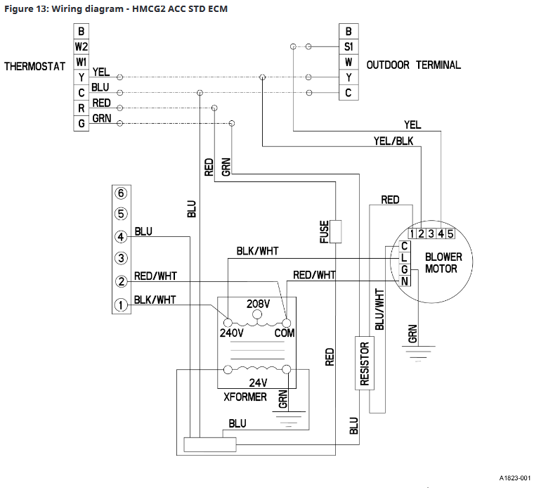
Yes it does have a G on the furnace control board which is what I was thinking in my overly wordy original post may give me that "less cool" and "cooling" modes. Your cleverer solution above is exactly what I'm trying to figure out if it may work. I assumed that the condenser is just looking for a signal to call for the "low cool" and that it gets it from the thermostat, so that's why I was thinking that even though I only have the single stage cooling mode on the furnace (Y) if the fan speed is slightly lower on the fan only (G) does that mimic the way that a 2 stage furnace that has a dedicated (Y and Y/Y2) terminal works. The condenser does not seem like it is communicating digitally to a furnace for the feedback to operate based on the bottom wiring diagram @109A_5 posted above so I believe its just the 24v signal that tells it, fan inside is on low or fan inside is on High.
0 -
If the fan-only side can be adjusted to give the proper airflow, that side of the equation shouldn't be an issue. I'm not in a position to look up the schematic of that outdoor unit right now, but judging by what @109A_5 posted above, the S1 terminal is an output that forces the indoor unit into the low cool fan speed. I don't know if that means there are other wires going to the outdoor unit, or if the outdoor unit decides to go into high cooling on its own & thus forces the indoor unit into high speed fan (or, more accurately, stops forcing the indoor unit into low speed.)
1 -
Thanks @ratio I see what you mean as far as the wire only comes off of the outside unit and goes directly to the y/y2 position in the wiring diagram with no other wires on that position. So I see what you mean that it is possible that it's just an output from the condenser to energize the 24v on the furnace board and activate that next stage.
What you see in the bottom diagram from @109A_5 is accurate, the unit outside only gets 3 wires from outside to the inside furnace control board.
0 -
I fat fingered something when I was composing my original post. At that time I could not edit it or add another post. And it only seems to be with this post, very odd… If I can I will add this to my post later so it makes sense to others. I PMed the @PeteA with much of this below.
Not sure what that mode Dip switch SW5-3 does , maybe switches between ECM motor control (newer way) OR utilizing a relay on the furnace's control board switching the motor speed (old way).
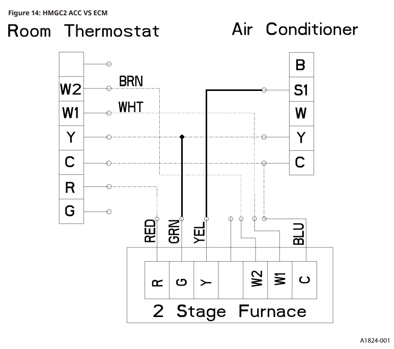
Anyway maybe this wiring is what you were saying in your post (image below), I got a bit confused it was late. Depending on what the terminal S1 actually does (logically) the G and the Y wires (diagram below) may need to be switched at the furnace.
Not sure with the OEM drawing above S1 to Y/Y2 who is the signal source S1 or Y/Y2, which is the input and which is the output ? If it is the furnace is the output, it is probably timed by the control board, if the signal source is the modulating condenser unit it may work from the line temperatures to determine the system load and modulate its self and then the evaporator blower fan accordingly. Which to me is what the ACC STD ECM drawing above implies. However in this case you would be working with the ACC VS ECM diagram which I modified below. There may be other ways.
 National - U.S. Gas Boiler 45+ Years Old
Steam 300 SQ. FT. - EDR 347
One Pipe System0 -
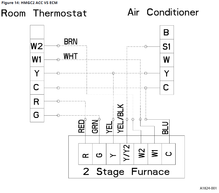
Did a little research on the Trane 2 stage furnace and the York Vari speed condensing unit. There is more to operating that compressor as a vari speed than just connecting a high and low (Y1 and Y2) from the thermostat to the furnace and the AC unit. You really need to find a matching York Furnace that can accommodate that third SI wiring terminal on the Condenser.
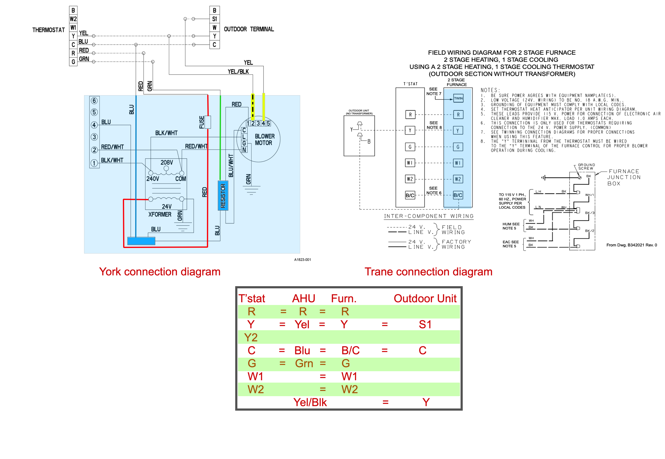
In this diagram, the blue shaded area is the wiring connection for the air moving unit (Trane furnace or the York AHU). You can see that there are several missing pieces. There is nothing that you can connect the S1 of your York unit to, on the Trane furnace. Trying to operate the York in a vari speed is impossible unless you have the two yellow wires that are connected to the vari speed motor. The S1 is not a "on off" (24 VAC = on and no voltage = off) terminal like all the other wires of the electrical system. The S1 is communicating the compressor speed to match up with the indoor blower speed.
I don't believe you are going to get what you are looking for with a Nest, York vari Speed and a Trane two stage. They don't speak the same language.
For now you may get the York to operate as a full on / full off condensing unit. But you really need to look into getting a matching York furnace that will operate the vari speed compressor.
That is just my opinion.
Good Luck
Edward Young Retired
After you make that expensive repair and you still have the same problem, What will you check next?
1 -
@EdTheHeaterMan thank you very much for looking at the different pieces of equipment. I knew an odd ball like this needed those expert eyes to look it over. For the time being it will just be operated as a single stage and maybe next year I’ll have him put together some dough to update the furnace to have everything operating as efficiently as possible.
thanks for taking the time out, it’s appreciated.0 -
Kind of wondering if this provides backward compatibility for 2 stage AC. looking at the wiring diagrams above, I see nothing that implies the thermostat is in control of the 2 stage operation. Just a call for AC or not. If there is a call for AC, the outdoor unit is in control, and can change evaporator blower speed as needed.
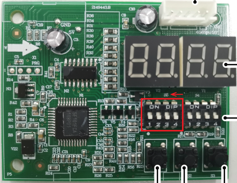
Seems there maybe different board versions, this is one example.
 National - U.S. Gas Boiler 45+ Years Old
Steam 300 SQ. FT. - EDR 347
One Pipe System0 -
@109A_5 Thanks for the additional info. I also obviously am not sure because I assumed most of the logic of ramping up and slowing down the condenser speeds would be controlled by the onboard logic as the sensors built into it would measure all of the outgoing temps and pressures on the line sets and adjust accordingly. It also seemed to me that the 3 wires coming in from the outdoor unit was to simply detect a low or normal call for AC which was why I had hoped to utilize the "G" position as the possible "low" but when @ratio pointed out that it looked like the wire was an "output" only it stumped me a little whether that "output" would be the 24v to trigger the Y contactor on the furnace control board or not. I will have the opportunity to try and test different things once my buddy helps me with the final connections of the lineset.
The picture of the circuit board is very similar to what I saw when I was wiring up the condenser, I didn't think to take a picture of it yet because i was only connecting the power and low voltage wires not adjusting anything at the time.
0 -
@PeteA said "I assumed most of the logic of ramping up and slowing down the condenser speeds would be controlled by the onboard logic as the sensors built into it would measure all of the outgoing temps and pressures on the line sets and adjust accordingly."
This is exactly how the York system works. the Logic of the PCB on the York condenser will optimize the compressor speed outdoor fan speed and adjust the indoor blower speed to complete the operation of the system to the most efficient use of electric power. The problem is that there is no standardization of communicating control systems, so the York will not talk to the Trane. They speak different languages.
I wonder if Google Translate can help here?
Edward Young Retired
After you make that expensive repair and you still have the same problem, What will you check next?
1 -
@EdTheHeaterMan I'm going to buy the furnace and the condenser each a cell phone with an international unlimited plan and google translate app so they can chat away with each other regardless of which language they are speaking 😜❄️☃️🔥
 1
1 -
Just following up on this to let everyone know that I was able to run the system fine by leaving off the S1 wire and just connecting the Y and the C to the furnace. The weather has changed pretty quickly in NJ so we really didn't get to push it to the max to see how it handled any significantly how days but it does run and I did not have to change any dip switch settings or connect the S1.
I do have a relay which I can always install at a later time if we really feel the need to create to dual cool modes but without any real time left in the season I don't feel like it would really be worth the effort.
Thanks as always to everyone for reviewing the equipment I have and offering suggestions for ensuring we get it running.
0


Categories
- All Categories
- 87.6K THE MAIN WALL
- 3.3K A-C, Heat Pumps & Refrigeration
- 59 Biomass
- 430 Carbon Monoxide Awareness
- 124 Chimneys & Flues
- 2.2K Domestic Hot Water
- 5.9K Gas Heating
- 120 Geothermal
- 168 Indoor-Air Quality
- 3.8K Oil Heating
- 78 Pipe Deterioration
- 1K Plumbing
- 6.6K Radiant Heating
- 394 Solar
- 16K Strictly Steam
- 3.5K Thermostats and Controls
- 56 Water Quality
- 51 Industry Classes
- 50 Job Opportunities
- 18 Recall Announcements